TOWARDS A PROGRAMMABLE DATAPLANE
A Dissertation
Presented to the Faculty of the Graduate School of Cornell University
in Partial Fulfillment of the Requirements for the Degree of Doctor of Philosophy
by Han Wang May 2017
c
2017 Han Wang ALL RIGHTS RESERVED
TOWARDS A PROGRAMMABLE DATAPLANE Han Wang, Ph.D.
Cornell University 2017
Programmable network dataplanes can significantly improve the flexibility and func-tionality of computer networks. This dissertation investigates two building blocks of network dataplane programming for network devices: the packet processing pipeline and network device interface. In the first part of the dissertation, we show that design-ing packet processdesign-ing pipelines on hardware can be fast and flexible (programmable). A network dataplane compiler and runtime is presented that generates a custom FPGA dataplane designed and built from a dataplane programming language called P4 (pro-gramming protocol independent packet processors). P4FPGA generates designs that can be synthesized to either Xilinx or Altera FPGAs. We have benchmarked several repre-sentative P4 programs, and the experiments show that code generated by P4FPGA runs at line-rate at all packet sizes with latencies comparable to commercial ASICs. In the second part of the dissertation, we present a programmable network interface for the net-work dataplane. We show that a software programmable physical layer (programmable PHY) can capture and control the timing of physical layer bits with sub-nanosecond precision greatly increasing precision in network measurements. The benefits of a pro-grammable PHY is demonstrated with an available bandwidth estimation algorithm and a decentralized clock synchronization protocol that provides bounded precision where no two clocks differ by more than tens of nanoseconds.
BIOGRAPHICAL SKETCH
Han Wang attended the University of Auckland from 2003 to 2007 for his undergradu-ate studies in Computer Systems Engineering. Han spent a few months working as an embedded system software engineer before starting his PhD program in Electrical and Computer Engineering in Cornell University in 2008. He spent the first two years work-ing with Professor Francois Guimbretiere on low power embedded system design before joining Hakim Weatherspoon’s group to focus on system and networking research. In 2013 and 2014, Han spent two summers at Nicira/VMware working on Software De-fined Networking (SDN) controller and dataplane projects. In 2014 and 2015, Han Wang helped building the initial prototypes that form the basis of Waltz Networks Inc with Kevin Tang and Nithin Michael. In 2016, Han Wang accepted a position at Barefoot Networks Inc to pursue what he believed as the next generation programmable switch ASICs and compiler technology.
ACKNOWLEDGEMENTS
First, I would like to express my deepest gratitude to my advisor, Hakim Weatherspoon, who has profoundly influenced my life at Cornell. I have been extremely lucky to have an advisor who put enormous trust and confidence into my ability, who offered unpar-alleled guidance for me to become an independent researcher, and who provided the complete freedom for me to pursue exciting ideas. I could not ask for more from an advisor.
My work wouldn’t be possible without my wonderful collaborators. I would like to thank Ki Suh Lee, for his extrodinary ability in system programming and his meticulous attention to details. Without him, the SoNIC project would never be possible. Hyun Tu Dang and Robert Soule are the co-authors of the P4Paxos project. Thanks to Tu for taking the leap-of-faith to use my P4 compiler. Thanks to Robert for being a great collaborator and a great advisor. His help on my writing and presentation skills have been invaluable in the late stage of my PhD career. Jamey Hicks introduced me to Blue-spec and Connectal, which has been enormously helpful for the development P4FPGA. Thanks to Jamey for his unreserved help and guidance during my visit to MIT and after I returned to Cornell.
I would like to thank Hakim Weatherspoon, Emin Gun Sirer, Rajit Manohar for serving on my thesis committee, and giving me valuable feedback on the works.
Kevin A. Tang, Nithin Michael and Ning Wu have been another source of inspira-tion for my PhD career. Thanks to Kevin and Nithin for giving me the opportunity to participate in their early endeavors of Waltz Networks Inc. The experience of working with an early stage start-up is an invaluable lesson.
I would like to thank Alan Shieh and Mukesh Hira for taking me as an intern at VMWare networking group in Palo Alto. Thanks to Baris Kasikci, Jeff Rasley for being wonderful friends, team mates at VMWare. I enjoyed the brainstorming, and lunch
discussions.
I am gratefully to many friends at Cornell. Songming Peng, Yuerui Lu, Han Zhang, Pu Zhang, Xi Yan, Ryan Lau, Weiwei Wang, Jiajie Yu, Jiahe Li, Qi Huang, Zhiming Shen, Weijia Song, Haoyan Geng, Erluo Li, Zhefu Jiang, Qin Jia, and too many others to mention. I cannot forget all the parties, game nights, mid-night conversations we have had. You made my life at Ithaca much more fun.
Last I would like to thank my family. I thank my parents, dad Xijin Wang, mom Qiaofeng Li, for their enduring love, support and belief, without which I would not have finished this journey. I thank my wife Fan Zhang, for her love and faith in me through the ups and downs of my PhD career. It is the optimism and happiness from her that drives me through the long journey. I dedicate this dissertation to them all.
TABLE OF CONTENTS
Biographical Sketch . . . iii
Dedication . . . iv
Acknowledgements . . . v
Table of Contents . . . vii
List of Tables . . . xi
List of Figures . . . xii
1 Introduction 1 1.1 Network Dataplane Programming . . . 2
1.2 Problems with Existing Network Dataplanes . . . 5
1.3 The Rise of Programmable Network Dataplanes . . . 7
1.4 Challenges in the Programmable Dataplane Design . . . 9
1.4.1 Lack of Programmable Network Dataplanes: Packet Processing Pipeline . . . 9
1.4.2 Lack of Programmable Network Dataplanes: Network Interface 11 1.5 Contributions Towards a Programmable Network Dataplane . . . 12
1.6 Organization . . . 13
2 Scope and Methodology 15 2.1 Scope: Understanding the Network Dataplane . . . 15
2.1.1 Dataplane Programming . . . 16
2.1.2 Network Protocol Stack . . . 18
2.1.3 Fast and Flexible Packet Processors . . . 22
2.1.4 Precise Packet Timing Control with a Programmable PHY . . . 26
2.2 Methodology . . . 28
2.2.1 Systems . . . 28
2.2.2 Evaluation . . . 30
2.3 Summary . . . 33
3 Towards a Programmable Network Dataplane: P4FPGA and Pro-grammable Packet Processing Pipelines 34 3.1 Background . . . 36
3.2 Design . . . 41
3.2.1 Programmable Pipeline . . . 43
3.2.2 Fixed-Function Runtime . . . 46
3.2.3 Control Plane API . . . 48
3.2.4 Extension . . . 49 3.3 Implementation . . . 50 3.3.1 Optimization . . . 50 3.3.2 Prototype . . . 53 3.4 Evaluation . . . 54 3.4.1 Case Studies . . . 55
3.4.2 Microbenchmarks . . . 58
3.5 Application: Hardware Accelerated Consensus Protocol . . . 67
3.5.1 Background . . . 68
3.5.2 Design . . . 70
3.5.3 Discussion . . . 78
3.6 Summary . . . 80
4 Towards a Programmable Network Dataplane: SoNIC and Programmable PHYs 84 4.1 Design . . . 86
4.1.1 Access to the PHY in software . . . 86
4.1.2 Realtime Capability . . . 87
4.1.3 Scalability and Efficiency . . . 89
4.1.4 Precision . . . 90 4.1.5 User Interface . . . 90 4.1.6 Discussion . . . 93 4.2 Implementation . . . 93 4.2.1 Software Optimizations . . . 94 4.2.2 Hardware Optimizations . . . 97 4.3 Evaluation . . . 101 4.3.1 Packet Generator . . . 101 4.3.2 Packet Capturer . . . 103 4.3.3 Profiler . . . 105
4.4 Application: Measuring Available Bandwidth . . . 106
4.4.1 Background . . . 108
4.4.2 Design . . . 112
4.4.3 Implementation . . . 119
4.4.4 Evaluation . . . 121
4.5 Application: Precise Clock Synchronization . . . 141
4.5.1 Background . . . 142 4.5.2 Design . . . 147 4.5.3 Implementation . . . 155 4.5.4 Evaluation . . . 158 4.6 Summary . . . 165 5 Related Work 166 5.1 Programming Network Elements . . . 166
5.1.1 Hardware . . . 166 5.1.2 Software . . . 166 5.1.3 Language . . . 167 5.2 Network Applications . . . 169 5.2.1 Consensus Protocol . . . 169 5.2.2 Timestamping . . . 170 5.2.3 Bandwidth Estimaton . . . 171
5.2.4 Clock Synchronization . . . 173
6 Future Direction 176 6.1 Rack-scale Computing . . . 176
6.2 Scaling to 100G . . . 177
6.3 Packet Scheduling . . . 177
6.4 Distributed and Responsive Network Control Plane . . . 178
7 Conclusions 179 A Network Concepts 181 A.1 Networking Basic Terminology . . . 181
A.2 Network Layering Model . . . 182
A.3 Packet Encapsulation . . . 183
A.4 Switch and Router . . . 184
B IEEE 802.3 Standard 186 C Language and Frameworks 190 C.1 Bluespec System Verilog . . . 190
C.2 Connectal Framework . . . 191
C.2.1 Top level structure of Connectal applications . . . 192
C.2.2 Development Cycles . . . 193
D FPGA Implementation 195 D.1 P4FPGA Hardware Implementation . . . 195
D.1.1 NetFPGA SUME . . . 195
D.1.2 Hardware Software Interface . . . 198
D.1.3 Packet Processing Pipeline Templates . . . 202
D.1.4 Code Generation . . . 207
D.2 SoNIC Hardware Implementation . . . 215
D.2.1 Hardware Overview . . . 215
D.2.2 PCI Express . . . 216
D.2.3 Transceivers . . . 218
D.2.4 DMA Engine . . . 219
D.2.5 Ring Buffer . . . 221
D.2.6 BlockSync and Gearbox . . . 227
D.3 DTP Hardware Implementation . . . 235
D.3.1 Altera DE5 . . . 235
D.3.2 Physical Layer Implementation . . . 235
D.3.3 Control Interface . . . 238
D.3.4 Bluespec Implementation . . . 238
LIST OF TABLES
2.1 Dell server specifications from year 2008 to 2016, Xeon CPUs in 2008
does not have per-core L2 Cache, instead it uses per-socket L3 Cache. . 22
2.2 Broadcom Trident-series switch ASIC specification from year 2008 to 2016 . . . 23
2.3 Xilinx Virtex-series FPGA specification from year 2008 to 2016 . . . . 24
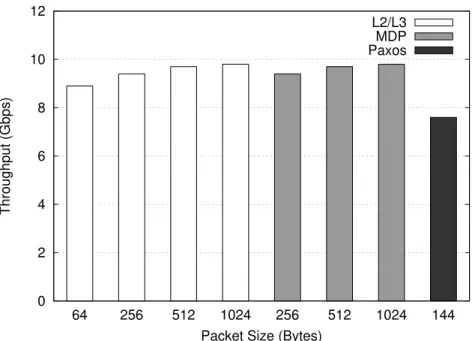
3.1 Example applications compiled by P4FPGA and lines of code (LoC) in P4 and Bluespec. l2l3.p4 implements a L2/L3 router, mdp.p4 im-plements a variable packet length, financial trading protocol parser, paxos.p4 implements a stateful consensus protocol. . . 55
3.2 Processing time breakdown, cycles @ 250MHz. . . 57
3.3 Latency comparing to vendors. The numbers of cut-through and store-and-forward switches are from [193] . . . 57
3.4 Area and frequency of fixed function runtime. . . 65
3.5 BCAM and TCAM Resource Utilization on Virtex 7 XCVX690T, which has 1470 BRAM blocks, 866400 Flip-flops and 433200 LUTs. We show resource utilization as percentage as well as actual amount of resource used. . . 65
4.1 DMA throughput. The numbers are average over eight runs. The delta in measurements was within 1% or less. . . 99
4.2 Parameter setting for existing algorithms. G is the gap between packet trains. R is the rate of probe. N is the number of probe packets in each sub-train. D is the gap between each sub-train. . . 117
4.3 Application Programming Interface. . . 121
4.4 IPD and IPG of uniformly spaced packet streams. . . 126
4.5 Estimation with different probe train length. . . 131
4.6 Estimation results with different probe packet size. . . 131
LIST OF FIGURES
2.1 Different types of bits on dataplane, green color represents inter-packet gap, red color represents packet header, yellow color represents packet
payload. . . 16
2.2 A programmable protocol parser that can parse financial trading proto-col at high speed and low latency. . . 17
2.3 A programmable dataplane that can pace packets at sub-nanosecond precision. . . 17
2.4 Header definitions for MDP.p4. . . 19
2.5 IEEE 802.3 10 Gigabit Ethernet Network stack. . . 20
2.6 FPGA development boards used for our research. . . 31
2.7 Our path on the National Lambda Rail. . . 31
2.8 Simple evaluation setup. . . 32
3.1 Subset of a P4 program to count UDP packets. . . 38
3.2 Example P4 Abstract Architecture. . . 39
3.3 P4FPGA Framework Overview. . . 41
3.4 P4FPGA Runtime and Pipeline. . . 42
3.5 Application throughput for L2L3, MDP and Paxos. . . 59
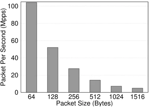
3.6 Runtime forwarding performance in gigabits per second (left) and mil-lions packets per second (right) with a simple forwarding application on a 6-port switching architecture. . . 61
3.7 Parser Latency v.s. Number of Headers parsed . . . 62
3.8 Parser Throughput v.s. Number of Headers parsed . . . 62
3.9 Processing latency versus number of tables . . . 63
3.10 Pipeline Latency v.s. Number of Actions. . . 64
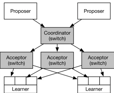
3.11 The Paxos protocol Phase 2 communication pattern. . . 68
3.12 A switch-based Paxos architecture. Switch hardware is shaded grey, and commodity servers are colored white. . . 70
3.13 Paxos packet header and parsers. . . 74
3.14 Coordinator code. . . 75
3.15 Acceptor code. . . 83
4.1 Example usages of SoNIC . . . 88
4.2 Packet Generator and Capturer. . . 91
4.3 SoNIC architecture. . . 92
4.4 Throughput of packing . . . 96
4.5 Throughput of different CRC algorithms. . . 96
4.6 Throughput of packet generator and capturer. . . 102
4.7 Comparison of packet generation at 9 Gbps. . . 103
4.8 Comparison of timestamping. . . 105
4.9 IPDs of Cisco 4948 and IBM G8264. 1518B packets at 9 Gbps. . . 106
4.11 Comparison of traffic pattern before and after passed through middlebox 115
4.12 Generalized probe train model. . . 116
4.13 MinProbe Architecture. . . 120
4.14 National Lambda Rail Experiment. . . 122
4.15 Controlled Experiment Topologies. . . 123
4.16 The time series and wavelet energy plots for cross traffic used in con-trolled experiments. Figure 4.16a shows a time series of a CAIDA trace in three different time scales: 10ms, 100ms and 1s. Coarser time scale means longer averaging period, hence less burstiness. Fig-ure 4.16b shows the corresponding wavelet energy plot for the trace in Figure 4.16a. Figure 4.16c shows three different traces with differ-ent traffic burstiness of the same time scale. Figure 4.16d shows the corresponding wavelet energy plot, with higher energy indicating more burstiness. . . 124
4.17 Available bandwidth estimation in a dumb-bell and parking-lot topol-ogy under CBR traffic. Both cross traffic and probe traffic share one bottleneck with the capacity of 10Gbps. The x-axis represents the actual available bandwidth of the bottleneck link. The y-axis rep-resents the estimation by MinProbe . This evaluation demonstrates MinProbe ’s ability to accurately measure the available bandwidth and achieve the estimation with minimal probing overhead. . . 127
4.18 Scatter-plot showing the queuing delay variance of probe packets ver-sus the probe rate. The cross traffic rate are constant at 1Gbps, 3Gbps, 6Gbps and 8Gbps. We used probe with N=20, R=[0.1:0.1:9.6]Gbps, G=10us, D=4ms. . . 128
4.19 The distribution of probe packet sizes from the CAIDA trace. . . 132
4.20 Estimation with probe packets drawn from the CAIDA trace. . . 133
4.21 Bandwidth estimation accuracy with different cross traffic burstiness. On y-axis, we turn the knob from no clustering to batching. On x-axis, we turn the knob on cross traffic packet size distribution from uniform distribution to log-normal distribution. We plot the graph for different cross traffic rate: 1Gbps, 3Gbps, 6Gbps and 8Gbps. . . 135
4.22 Bandwidth estimation of CAIDA trace, the figure on the left is the raw data trace, the figure on the right is the moving average data. . . 136
4.23 Measurement result in NLR. . . 137
4.24 Software Routers do not exhibit the same fidelity as MinProbe . . . 139
4.25 Estimating Available Bandwidth on different switches. . . 141
4.26 Common approach to measure offset and RTT. . . 144
4.27 Clock domains of two peers. The same color represents the the same clock domain. . . 144
4.28 Low layers of a 10 GbE network stack. Grayed rectangles are DTP sublayers, and the circle represents a synchronization FIFO. . . 156
4.29 DTP enabled four-port device. . . 156
4.31 Precision of DTP and PTP. Atickis 6.4 nanoseconds. . . 160
4.32 Precision of DTP daemon. . . 161
A.1 Encapsulation of data as it goes down the network stack. . . 184
A.2 Network Dataplane Built with Endhosts, Switches and Routers. . . 185
B.1 IEEE 802.3 10 Gigabit Ethernet Network stack. . . 187
B.2 IEEE 802.3 64b/66b block format. . . 188
D.1 Cable Pin-out to use GPU power source for PCI Express Power Con-nector. . . 196
D.2 P4FPGA Clock Domains. . . 197
D.3 Simple Connectal Example. . . 198
D.4 Paxos Request Interface Definition in Connectal. . . 199
D.5 Paxos Indication Interface Definition in Connectal. . . 200
D.6 An example packet header in P4FPGA in Bluespec. . . 203
D.7 Parser implementation. . . 204
D.8 Match table implementation. . . 206
D.9 Load State Rule Generation. . . 209
D.10 Extract State Rule Generation. . . 210
D.11 Collect All Generated Rules to State Machine. . . 210
D.12 Match Table Typeclasses and Instances. . . 212
D.13 Generated Control Flow. . . 214
D.14 SoNIC PCI Express Configuration. . . 217
D.15 SoNIC PMA Configuration. . . 220
D.16 SoNIC DMA Descriptor Format. . . 222
D.17 Rx Circular Ring. . . 224
D.18 Tx Circular Ring. . . 226
D.19 BlockSync State Machine. . . 228
D.20 BlockSync State Machine Output Transition. . . 229
D.21 BlockSync State Machine Next State Computation. . . 230
D.22 40 bit to 66 bit gearbox logic. . . 232
D.23 66 bit to 40 bit gearbox logic. . . 234
D.24 DTP Top Level Module in Bluespec. . . 239
D.25 DTP Control API definition in Connectal. . . 240
D.26 DTP State Machine. . . 241
D.27 DTP INIT State Implementation. . . 242
D.28 DTP SENT State and SYNC State Implementation. . . 242
D.29 DTP Beacon Message Generation. . . 243
D.30 DTP Delay Measurement Implementation. . . 244
D.31 DTP Transmit Path Implementation. . . 245
D.32 DTP Receive Path Implementation. . . 247
CHAPTER 1 INTRODUCTION
Computer networks are critical to our society. They are the basis of large scale dis-tributed applications, such as search engines, e-commerce, and social networks, which have profoundly changed how we access information and interact with each other. These applications are hosted in data centers, where a large group of networked computer servers are connected by large-scale data center networks. Further, emerging new appli-cations, such as machine learning [140], and big data processing [134] are implemented in data centers. These data center networks, and networks in general, must be flexible to cope with new system architectures, higher performance requirements and stringent application demands.
The part of the network that performs all the heavy lifting is thenetwork dataplane. The network dataplane forwards and processes packets. Given the demands of continual technological development, a network dataplane needs to be fast, and needs to evolve over time. But currently, the dataplane is not directly accessible by network developers, operators or programmers. Instead, the programming to evolve the network has to go through a layer of software called the control plane. The control plane is typically co-located with the dataplane in the same network device (e.g. in a router). Enabling programmable access to the network dataplane is the focus of this dissertation.
This dissertation represents a step towards identifying and addressing the challenges of designing a framework for programmable dataplanes, which can significantly im-prove the flexibility and functionality of networks. To this end, we investigate two building blocks of the network dataplane programming for network devices: the packet processing pipeline and network device interface. We asked the research question:how can we build a programmable dataplane to improve network measurement, enable novel
network functionality, and accelerate development time from concept to prototype? We explore this question with two approaches: a programmable dataplane that automates generation of the network dataplane from a high-level dataplane programming language; and a programmable network interface that allows precise control and measurement of packet timing.
1.1
Network Dataplane Programming
Dataplane programming is distinct from control plane programming. The former en-ables programming of the entire network while the latter enen-ables programming network devices through interfaces exposed by control plane software. In order to illustrate the value of network dataplane programming, we discuss some concrete examples that are not possible through control plane programming alone.
Rapid Prototyping of Protocols Data center networks are often under one adminis-trative domain [4], which means a cloud provider, such as Google, Amazon, or Facebook can design their own network hardware and protocol suite to optimize for their network use cases. However, if a custom protocol cannot be supported by the network dataplane, deployment of custom protocols becomes difficult. The history of VxLAN (Virtual eX-tensible LANs) protocol deployment is a good example [131]. As the name VxLAN implies, the technology is meant to provide the same services to connected Ethernet end systems that VLANs (Virtual Local Area Network) do, but in a more extensible man-ner. Compared to VLANs, VxLANs are extensible with regard to scale of the network, and extensible with regard to the reach of their deployment. The idea of VxLAN was proposed initially in 2011 in a IETF (Internet Engineering Task Force) draft [131], as a method to efficiently support network virtualization at data center scale. However,
an efficient implementation of VxLAN in a router (or switch) ASIC (Application Spe-cific Integrated Circuit) was not available until 2014 [187], which inevitably affected the adoption of the new technology. A programmable dataplane allows network operators to rapidly prototype new protocols without waiting for the protocol to be fabricated into a commodity switch ASIC.
Accelerating Distributed Applications Data centers are built with hundreds of thou-sands of servers and network switches, with large distributed applications running on top of the servers. This is what we call thecloud. Increasingly, cloud providers are mov-ing towards addmov-ing accelerators, e.g., Graphical Processmov-ing Units (GPUs) [97], Field Programmable Gate Arrays (FPGAs) [43], Tensor Processing Units (TPUs) [201] to the cloud, to improve the performance of cloud applications, such as machine learning, video encoding, or artificial intelligence [140]. It is interesting to ask if the network dataplane can accelerate distributed applications, offloading work from the servers. For example, researchers have demonstrated how the Paxos distributed consensus protocol can be added to the network by implementing a portion of the protocol in network dat-aplane [57]. A similar trend can be found in the financial industry, which has used dataplane based acceleration in high frequency trading [71].
Precise Network Measurement The physical Layer (PHY) of the network dataplane can be used for precise network measurement if made accessible to programmers. For example, available bandwidth, which is defined as the maximum data rate that a process can send to another process without going over the network path capacity between the two, can be estimated with algorithms based on active probing [173]. Available band-width estimation algorithms work by examining and detecting any changes in measured way delay of probe packets to infer queuing (buffering) in the network. The
one-way delay is the amount of time for a packet to travel from the sender to the receiver of the packet. An increase in one-way delay implies more buffering, queuing or congestion in the network path, and therefore less available bandwidth. Being able to precisely con-trol and measure active probes in the dataplane enables accurate bandwidth estimation algorithms.
Clock Synchronization Servers in data center networks are loosely synchronized. Existing clock synchronization protocols provide different levels of precision, includ-ing NTP [141] and PTP [12]. Synchronization precision is the maximum difference between any two clocks [100]. NTP can provide millisecond to microsecond precision in a Local Area Network (LAN), and PTP can provide tens of nanosecond to microsec-ond precision in a LAN if properly configured [111, 112]. In particular, PTP employs many techniques to remove uncertainties in measured round-trip times. For example, hardware timestamping is commonly used and PTP-enabled switches are deployed to minimize network jitter. Nonetheless, it is not possible to completely remove the net-work jitter and non-deterministic delays. The accuracy of PTP can be as close as hun-dreds of nanoseconds, and can degrade to tens of microseconds depending on network conditions [112].
The physical layer of network devices can be used to implement a decentralized clock synchronization protocol. By doing so, the clock synchronization protocol elimi-nates most non-deterministic elements in clock synchronization protocols. Further, the protocol can send control messages in the physical layer for communicating hundreds of thousands of protocol messages without interfering with higher layer packets. Thus, it has virtually zero overhead since no load is added to layers 2 or higher at all.
1.2
Problems with Existing Network Dataplanes
Programming the network is meant to control the packet forwarding and processing be-havior of network elements. Anetwork elementis a computer system that can forward, filter, or modify network packets. It is challenging to design network elements with existing dataplanes to handle the above examples due to the following problems:
Flexibility or Performance, Pick One. The implementation of the network dataplane is often a trade-off between flexibility and performance. A flexible network dataplane can be built from conventional servers and CPUs, e.g., Click [98], RouteBricks [62], OpenvSwitch [164]. However, the end of Moore’s law [175] has made it more diffi-cult to build software-based network dataplanes to cope with increases in network link technology. In particular, while processors no longer scale in frequency, network link technology continues to increase exponentially (1Gbps, 10Gbps, 100Gbps, 400Gbps). Alternatively, network dataplanes are often built with hardware network elements (e.g., switches and routers). These hardware network dataplanes are fast, but not flexible. Hardware dataplanes can be implemented with ASICs. As the name implies, ASICs are manufactured for a specific set of applications (in this case, a set of network protocols). Dataplanes that are built with ASICs are often referred to asfixed-functiondataplanes. For example, the VxLAN example shows fixed-function dataplanes typically require a long, multi-year design cycle to support custom protocols.
Complex Programming Model and Vendor Centric Design. To keep up with changing requirements, computer architects have devised new families of computer chips. Network processors (NPs) are software programmable chips designed to pro-cess packets at line speed, but at 1/100th overall throughput compared to fixed function
ASICs [49]. Since the processing latency usually exceeds the packet inter-arrival time, multiple packets are typically processed concurrently. For this reason, network proces-sors usually consist of multi-threaded multiprocesproces-sors. Multi-threading has also been used extensively in network processors to hide pipeline stalls [49]. Further, complex in-struction sets and vendor-specific architectures result in complex programming models. Adopting a network processor often results in vendor lock-in to a particular provider’s solutions.
FPGAs are semiconductor devices that are based around a matrix of configurable logic blocks (CLBs) connected via programmable interconnects. While FPGAs can be reprogrammed to desired application or functionality requirements after manufacturing, other issues endemic to this chip set make them difficult to use for packet processing. The programming languages for programming FPGAs, such as Verilog or VHDL, are low level languages. Hardware design with complex control logic manifests itself at module boundaries as ad-hoc protocols and assumptions on signaling. Without consis-tent and clear semantics on protocols and signalings, designs tend to accumulate layer upon layer of such assumptions, often poorly documented (if documented at all) and poorly communicated between the designer of a module and the users of the module, which makes designing with Verilog difficult and prone to errors [147].
In order to support custom protocols or accelerate application logic, as discussed in the first two examples, both NPs and FPGAs based solutions require extensive effort to rewrite the protocol or logic to vendor-specific architectures, programming models or programming languages that are used by these reconfigurable devices.
Opaque, Non-programmable Components. Part of the network dataplane is not pro-grammable at all. For example, the physical layer is usually implemented in hardware,
and, consequently, its behavior cannot be modified through programs. The physical layer defines the means of transmitting raw bits and signals rather than logical data packets over a physical link connecting network nodes. The bit stream may be grouped into code words or symbols and converted to a physical signal that is transmitted over a hardware transmission medium. The physical layer provides a plethora of services to the upper layers of the network stack: modulation, line encoding, bit synchronization, circuit switching, forwarding error correction, and so on. Despite the rich services pro-vided by the physical layers, they are largely ignored by the system programmers as opaque components. The situation is further exacerbated by commodity network inter-face cards (NICs), which do not provide nor allow an interinter-face for users to access the PHY in any case. However, the physical layer has the most precise control over how bits are sent over the network link. The fact that operations on physical layers are agnostic to upper layers of the network stack provides a unique opportunity to implement accurate timestamping, network measurement and clock synchronization protocols.
1.3
The Rise of Programmable Network Dataplanes
Programmable network dataplanes can fundamentally change the way network elements are built and managed. They have the following distinct features from the existing data-planes.
Balancing Flexibility and Performance Programmable dataplanes balance flexibil-ity and performance. The key to this balancing act is a good abstraction for packet processing. A good abstraction must be high level enough, such that it allows software to be built on top of the abstraction that easily captures the intent of the packet process-ing task. However, the abstraction must also be at a low enough level, such that it can
be easily mapped to appropriate hardware for implementation.
A similar analogy can be found in Graphics Processing Units (GPUs) or Digital Signal Processing (DSP). In both cases, an abstraction exists to represent the underlying hardware. In the case of a GPU, a unit of execution is abstracted as a thread to be executed on one of the thousands of hardware cores available on a single GPU. In the case of DSP, the abstractions are key mathematical functions to transform signals, e.g., filtering functions like Finite Impulse Response (FIR) and Infinite Impulse Response (IIR) filter blocks, common math functions such as square root, cosine, sine, and Fast Fourier Transforms (FFT).
A common abstraction for packet processing ismatch-actionpipeline, first proposed by OpenFlow [137]. With the match-action abstraction, a packet processor can be mod-eled as a sequence of match and action pipeline stages. Each pipeline stage performs a different operation on the packets that flow through. Such abstraction can be mapped to FPGAs and next generation ASICs.
Programming with a Network Dataplane Language Languages can be built on top of the appropriate abstraction to allow developers to program the network dataplane. One example of this is the dataplane programming language, P4 [155], which stands for programming protocol-independent packet processors. P4 provides a set of pro-gramming constructs that represent the basic building block for packet processing, such as parser, match table, action block. Programmers are already using the language to implement a variety of novel applications including network telemetry tools [95] and advanced load balancers [94]. The language is platform-independent, which means it can be mapped to all of the dataplane implementation technologies: software, FPGAs, ASICs, NPs. The language is also architecture-independent, which means it can be used
to describe different dataplane architectures, such as bump-in-the-wire [28], which is often used to implement network functions, such as network proxies, and multi-port switching, that are commonly found in switches and routers.
Programmable PHYs Programmable physical layers (PHYs) provide the opportu-nity to improve upon and develop new network research applications which were not previously feasible. First, as a powerful network measurement tool, a programmable PHY can generate packets at full data rate with minimal interpacket delay. It also pro-vides fine-grain control over the interpacket delay. Second, a programmable PHY can accurately capture and timestamp incoming packets at any data rate. Further, this pre-cise timestamping can improve the accuracy of research based on interpacket delay. For example, a programmable PHY can be used to profile network components [113].
1.4
Challenges in the Programmable Dataplane Design
In this section, we describe the challenges inherent to research supporting programmable network dataplanes and explain two research questions that this dissertation addresses.
1.4.1
Lack of Programmable Network Dataplanes: Packet
Process-ing Pipeline
Packet processing pipelines are used by individual network elements to implement packet processing algorithms. Many features provided by network elements are packet processing tasks in one way or another: routing, firewall, tunneling, and encryption. A router processes packet headers, and redirects packets based on the header content. A
firewall filters packets based on content in a defined set of packet headers. A packet processing pipeline isflexible if it allows a user to specify complex packet processing tasks from simple high-level language constructs. A packet processing pipeline isfast
if the pipeline can scale to multiple network interfaces simultaneously, such as 10 or 25 Gbps network interfaces. Unfortunately, state-of-the-art packet processing pipelines are either flexible or fast – not both.
The challenge is in designing a flexibleandfast packet processing pipeline. Specif-ically, we address the research question: How can packet processing pipelines be as flexible as software processors, while achieving high performance close to hardware packet processors?
To address these challenges, a viable approach must enable users to specify the functionality of the pipeline, ideally through a programming language with high-level abstraction. A technique should minimize the effort to translate from a high-level spec-ification to a high performance hardware implementation. It should also be portable to different hardware targets based on the complexity of the application and resource uti-lization. Unfortunately, existing systems do not satisfy these requirements in full. NetF-PGA [128] offers a framework to implement high-performance, efficient packet pro-cessing pipeline in FPGA, but the users have to manually implement the desired packet processing algorithm in low-level hardware description language. OpenvSwitch [152] offers a flexible software packet processing pipeline, but the performance is limited to by the capability of host CPUs and the complexity of the processing algorithm.
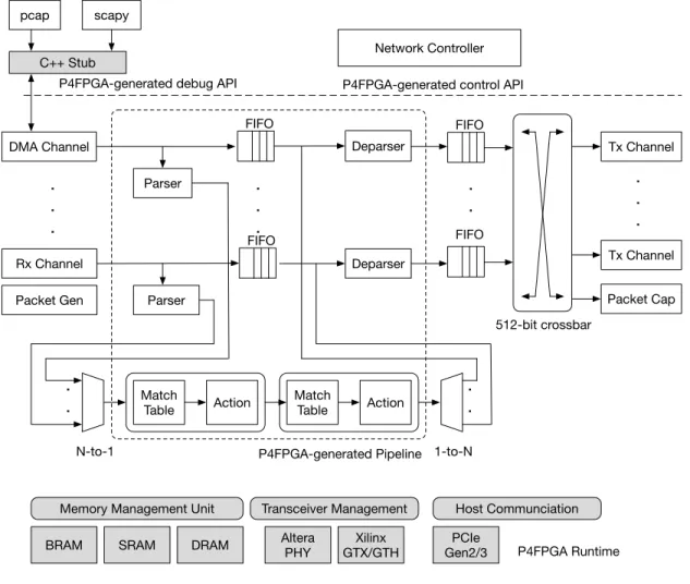
A dataplane compiler and runtime enables users to generate a custom packet pro-cessing pipeline from a high-level dataplane language. As an instance of the approach, we present P4FPGA, an open-source P4-to-FPGA compiler and runtime that is designed to be flexible, efficient, and portable. The compiler has two parts: a front end that turns
the P4 code into a target-independent intermediate representation (IR), and a back end that maps the IR to the FPGA backend target. In our case, the backend target is imple-mented using a high level hardware description language, Bluespec [147](See Appendix B). The P4-to-FPGA compiler outputs Bluespec source code from a templated imple-mentation, which is combined with a runtime framework (also written in Bluespec) to generate corresponding FPGA firmware. We describe our approach to compile P4 to FPGA target, embodied in P4FPGA, in more detail in Chapter 3. Then, we show a few prototypes of dataplane-accelerated applications built with the dataplane compiler in Section 3.5.
1.4.2
Lack of Programmable Network Dataplanes: Network
Inter-face
Commodity network interfaces do not provide programmable access to the idle bits be-tween packets. In other words, the PHY and Media Access Control (MAC) layer of the network protocol stack is opaque to system developers; they lackprogrammability. For example, an end host cannot use commodity network interfaces toaddorremove arbi-trary bits between packets, meaning it cannot accurately pacethe packets, thus means the packet send rate cannot controlled [113]. Furthermore, the end host cannot precisely
count the bits between adjacent packets using commodity network interfaces, which makes accurate timestamping difficult.
The challenge is in creating a programmable physical layer to provide access to physical layer bits while maintaining line rate performance. Specifically, we address the following question: How to build a programmable PHY to access every bit in the physical layer while maintaining link speed line rates?
To support a programmable physical layer, the approach must be able to access the PHY in software. Techniques should enable software to decide how many bits to insert or remove between packets. Furthermore, it is important to achieve real-time access, because the physical layer is always sending and receiving bits, usually at 10 gigabits per second and beyond. Finally, an approach must be able to scale to multiple line rate ports, such as 10 gigabit Ethernet ports to implement a network data plane for network measurement.
We explore a programmable PHY in order to grant users the flexibility to program every bit in the physical layer. As such, a user can implement an accurate network mea-surement application, create a covert timing channel, and even implement a distributed clock synchronization protocol. We investigate an approach to expose every bit in the physical layer of the network stack to software. As an instance of the approach, we present the design and implementation of SoNIC, a software network interface that im-plements the physical layer of the network protocol stack in software. We describe our methodology and prototype of SoNIC in more details in Chapter 4. Then, we present the design and implementation of a few prototypes, MinProbe, an available bandwidth estimator in Section 4.4, and DTP, a data center clock synchronization protocol in Sec-tion 4.5.
1.5
Contributions Towards a Programmable Network Dataplane
In this dissertation, we explore how to make every bit on a network dataplane pro-grammable that contributes towards a propro-grammable network dataplane.
First, we explore a programmable packet processing pipeline for the network dataplane. We show that designing packet processing pipelines on hardware can be
fast, and flexible (programmable). We built P4FPGA, a network dataplane compiler and runtime to generate a custom FPGA dataplane designed and built from the P4 language. We show that P4FPGA supports a variety of programmable dataplane implementations. For example, we created network routers, trading protocol parsers, a set of benchmark applications, and further highlight the benefit of dataplane programming with P4Paxos, an application that speeds up consensus protocol by offloading part of the protocol to the network dataplane.
Second, we investigate a programmable physical layer for the network data-plane. We show that a software programmable PHY can flexibly control every bit in the physical layer of the network, thus controlling inter-packet gaps. We designed and built SoNIC, a programmable PHY that runs at 10Gbps on a commodity server. SoNIC cap-tures and controls the timing of physical layer bits with sub-nanosecond precision. With precise timestamping and pacing, we implemented an available bandwidth estimation al-gorithm,MinProbe. We further improved the resource-efficiency of the programmable network interface with a hardware-based programmable PHY. We then implemented a fourth primitive: modify, to embed information into inter-packet gaps. With the modify primitive, we implemented a clock synchronization protocol, Datacenter Time Protocol (DTP). DTP is a decentralized protocol that eliminates many non-deterministic factors from the network. As a result, it provides bounded precision to the tens of nanosecond in a data center network.
1.6
Organization
The rest of the dissertation is organized as follows: Chapter 2 describes the scope of the problem and the methodology for investigation. Chapter 3 describes the design of
a programmable dataplane and its prototype implementation, P4FPGA that provides a framework to compile a high-level network specification to a hardware implementation. Section 3.5 presents new network applications implemented with P4FPGA: P4Paxos, a market data analyzer, and a set of micro-benchmarks. Chapter 4 details the design of a programmable PHY and an implementation of the approach, SoNIC that provides precise control of every bit and thus precise packet timing control and measurement. Section 4.4 presents two novel applications enabled by a programmable PHY: available bandwidth estimation, and data center clock synchronization.
CHAPTER 2
SCOPE AND METHODOLOGY
This chapter describes the problem scope and methodology of this dissertation. First, we clarify the scope of the problems by reviewing the design and implementation of a network dataplane. Then, we describe our methodology for evaluating and validating our research contributions.
2.1
Scope: Understanding the Network Dataplane
A single network element consists of two planes: the control plane and the dataplane. Thecontrol planeconfigures the forwarding and packet processing behavior, while the
dataplane forwards and processes packets based on configuration directives from the control plane. Network programming has several forms. First, manual configuration of network devices is a type of network programming. Network operators (e.g., net-work administrators) configure netnet-work devices (e.g., switches and routers) via a device-specific command line interface (CLI) to set up access control lists, routing policies and traffic load balancing. Second, software programs (e.g., network control programs writ-ten in C++ or Java) can automate the configuration process via a standard Application Programming Interface (API). Many of these programming tasks focus on the control plane and management plane tasks, which is referred to ascontrol plane programming. Finally, modifying network forwarding behavior and introducing new dataplane func-tionality is another form of network programming. For example, the network dataplane could be programmed to offload distributed consensus protocols to the network [56]. The network dataplane could also be programmed to enable tightly synchronized time in data center networks [112]. This dissertation explores the last type of network
pro-Direction of Traffic Flow
Packet Frame Inter-Packet Gap
Figure 2.1: Different types of bits on dataplane, green color represents inter-packet gap, red color represents packet header, yellow color represents packet payload.
gramming –dataplaneprogramming.
Dataplane programming is writing a program that can control of every single bit on a network dataplane. In particular, network dataplanes can be classified into two categories: the ability to program the bits that belong to a packet, i.e. packet headers and payload, and the ability to program bits that are between subsequent packets, i.e., the filling bits. (See Figure 2.1)
2.1.1
Dataplane Programming
Four basic primitives can be used to operate on the network dataplane. We can use these primitives to manipulate bits within packets and between packets. These four primitives are:add,delete,countandmodify.
These basic primitives can be performed on packet bits, which are usually part of the dataplane programming language specification. The add, deleteandmodifyprimitives enable new protocols. When dealing with packets, a set of bits are operated on, instead of individual bits. The set of bits could represent a packet header or payload. For example, a tunneling protocol needs primitives to add or remove headers. A router needs primitives to update values in packet header fields, such as decreasing the TTL (Time-To-Live) fields in the IP (Internet Protocol) header. Stateful operations, such as
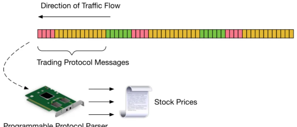
Direction of Traffic Flow
Programmable Protocol Parser Trading Protocol Messages
Stock Prices
Figure 2.2: A programmable protocol parser that can parse financial trading protocol at high speed and low latency.
Direction of Traffic Flow
Packet Bits
Middlebox First Bit
Direction of Traffic Flow
First Bit
Additonal Filling Bits Filling Bits 97ps
A programmable middlebox that is able to pace at sub-nanosecond precision
Figure 2.3: A programmable dataplane that can pace packets at sub-nanosecond preci-sion.
count, can be used, to accumulate packet statistics, e.g., the number of bytes received and transmitted.
With the add and delete primitives, the generated packet rate can be controlled. Adding filling bits between packets will slow down the instantaneous packet rate. Re-moving filling bits will increase the instantaneous packet rate and creates a burst of packets. For example, a middlebox that supports adding/removing filling bit can pre-cisely pace traffic at sub-nanosecond precision, as show in Figure 2.3. In this figure, each filling bit in 10 Gigabit Ethernet is about 97 picoseconds wide. The count primitive
enables the number of filling bits to be determined between packets. With thecount, the time elapsed between packets can be computed and measured at sub-nanosecond pre-cision. Furthermore, the modifyprimitive changes the values stored in the filling bits. With ’modify’, a time synchronization protocol can be created with zero-overhead at the network layer.
Programmable dataplanes can be easily extended to support custom protocols. For example, Figure 2.4 shows a snippet of a description of trading protocol called Market Data Protocol (MDP) which is used by the Chicago Mercantile Exchange [190]. The implementation of MDP is complicated by the fact that the protocol header is variable length. Figure 2.4 shows the header definitions for a book refresh message. Abookis an entity that keeps the most recent stock price. A book refresh message has a fixed header mdp t that is common to all MDP protocol messages, as well as a variable length header, refreshBook, with one or more entries refreshBookEntry. A fieldnumEntriesinrefreshBookdictates how many entries must be extraced by the parser.
2.1.2
Network Protocol Stack
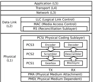
Before we discussing about dataplane programming further, we will provide a brief overview of the network protocol stack, focusing on the aspects related to the packet bits and filling bits. A network protocol stack is an implementation of a computer net-working protocol suite. An example is 10 Gigabit Ethernet protocol stack, as shown in Figure 2.5. A more detailed treatment of the network protocol stack can be found in Appendix B.
1 header_type mdp_t { 2 fields { 3 msgSeqNum : 32; 4 sendingTime : 64; 5 msgSize : 16; 6 blockLength : 16; 7 templateID : 16; 8 schemaID : 16; 9 version : 16; 10 } 11 } 12 13 header_type event_metadata_t { 14 fields { 15 group_size : 16; 16 } 17 } 18 19 header_type refreshBook { 20 fields { 21 transactTime : 64; 22 matchEventIndicator : 16; 23 blockLength: 16; 24 numEntries: 16; 25 } 26 } 27 28 header_type refreshBookEntry { 29 fields { 30 mdEntryPx : 64; 31 mdEntrySize : 32; 32 securityID : 32; 33 rptReq : 32; 34 numberOfOrders : 32; 35 mdPriceLevel : 8; 36 mdUpdateAction : 8; 37 mdEntryType : 8; 38 padding : 40; 39 } 40 }
Application (L5) Transport (L4) Network (L3) Data Link (L2) Physical (L1)
LLC (Logical Link Control) MAC (Media Access Control) RS (Reconcilliation Sublayer)
PCS( Physical Coding Sublayer) PCS3
PCS2 PCS1
TX RX
PMA (Physical Medium Attachment) PMD( Physical Medium Dependent)
Encoder Decoder
Scrambler Descrambler
Gearbox Blocksync
Figure 2.5: IEEE 802.3 10 Gigabit Ethernet Network stack.
Packet Bits The packet bits exist in the data link layer and above (Layer 2 to 5; L2 to L5). We discuss packet bits in the context of the most common protocol on the Internet – the Transmission Control Protocol/Internet Protocol (TCP/IP protocol stack) . TCP/IP works as follows: to send a chunk of data between applications on separate networked systems, the application layer (L5 in Figure 2.5) makes sure that the data is sent in a format that will be understandable by the recipient. Then, the transport layer (TCP) splits the application data into chunks that can fit into the maximum data packet size. It then attaches a sequence number to each packet, specifying packet order. The sequence number allows the recipient to re-assemble the data correctly at the other end. Next, the network layer (IP) attaches the IP address of the sender and the receiver to the packet, so that the network can route the messages to the destination. Finally, the link layer attaches a MAC (Media-Access-Control) address of the sender and the recipient, allowing the packets to be directed to a specific network interface on the host machine.
Filling Bits The filling bits exist in the Physical Layer (PHY) of the 10GbE protocol stack. PHY of 10 GbE consists of three sublayers: the Physical Coding Sublayer (PCS), the Physical Medium Attachment (PMA) sublayer, and the Physical Medium Depen-dent (PMD) sublayer. The PMA and PMD sublayers are responsible for clock recovery and (de-)serializing the bitstream. The PCS performs the blocksync and gearbox (we call this PCS1), scramble/descramble (PCS2), and encode/decode (PCS3) operations on every Ethernet frame. The filling bits (also called the idle characters) are special control characters that are used to fill any gaps between two Ethernet frames.
Network Interface Thenetwork interfaceimplements the physical (PHY) and media access (MAC) layers of the network stack. On the receiving path, the network interface converts the bitstream to packets, which on the transmitting path, it does the reverse. A network interface can be a network interface card on commodity servers. It can also be part of the silicon chip (e.g., FPGA) that implements PHY and MAC.
Packet Processing Pipeline Packet processing refers to the wide variety of algorithms that are applied to a packet of data or information as it moves through the various net-work elements of a communications netnet-work. Thepacket processing pipelineforwards, drops and/or modifies packets. Consider a packet processing pipeline inside an Inter-net Procotol (IP) router. The pipeline receives an IP packet from one of its Inter-network interfaces. First it checks a routing table to determine the next hop interface to send the packet to. Next, the pipeline processes and modifies the packet by updating its Time-To-Live (TTL) field and checksum fields. Finally, the pipeline sends the packet to the next router via an outgoing network interface.
2008 2012 2016
Model Xeon X5492 Xeon E5-4650 Xeon E7-8890
Core Count 4 8 24 Clock Frequency 3.4 GHz 2.8 GHz 2.2 GHz Process technology 45nm 32nm 14nm L2 Cache - 8 x 256 KB 24 x 256KB L3 Cache 12MB 20MB 60MB DRAM Frequency 1600MT/s 4x1600MT/s 4x1866MT/s Release price $1279 $3620 $7174
Table 2.1: Dell server specifications from year 2008 to 2016, Xeon CPUs in 2008 does not have per-core L2 Cache, instead it uses per-socket L3 Cache.
2.1.3
Fast and Flexible Packet Processors
Networks would benefit from fast and flexible packet processors. If a packet processor can process custom header bits, it would simplify the design and deployment of new network protocols. Similarly, if a packet processor can handle custom payload bits, critical network functions, such as packet classification and consensus protocol, can be offloaded to network dataplane. At the same time, a packet processor must be fast. For example, data center network bandwidth has been growing steadily: 10Gbps Ethernet is prevalent, 25Gbps is gaining traction, and 100 Gbps is on the horizon as of the time of writing this dissertation. Handling packet forwarding at line rate while performing complex packet processing requires significant computation power and programmabil-ity. Unfortunately, none of the existing network dataplanes can achieve both flexibility and performance at the same time.
We surveyed three dataplane implementation technologies from 2008, 2012, and 2016, to understand how different types of network dataplanes have evolved and why existing dataplanes lack flexibility or performance; that is, network dataplanes are either flexible (programmable) or performant, but not both.
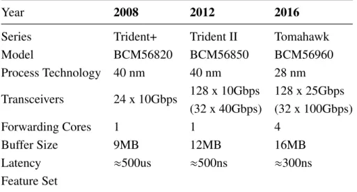
Year 2008 2012 2016
Series Trident+ Trident II Tomahawk
Model BCM56820 BCM56850 BCM56960 Process Technology 40 nm 40 nm 28 nm Transceivers 24 x 10Gbps 128 x 10Gbps 128 x 25Gbps (32 x 40Gbps) (32 x 100Gbps) Forwarding Cores 1 1 4 Buffer Size 9MB 12MB 16MB Latency ≈500us ≈500ns ≈300ns Feature Set
Table 2.2: Broadcom Trident-series switch ASIC specification from year 2008 to 2016
Software Packet Processors Software packet processors are flexible but not fast. Software packet processors are software programs that are written in high level program-ming language, such as C or C++, and executed on general purpose CPUs. A 25Gbps network interface can receive a minimum sized (64B) packet every 19.2ns. However, at this speed, even a single access to a last level cache would take longer than the ar-rival time of a packet. Processing packets in a software dataplane is challenging, even when using all the advanced software techniques, such as kernel bypass, receive side scaling, and data direct I/O [62]. Worse, CPU performance is unlikely to improve be-cause of stalled frequency scaling [175]. Table 1 summarizes three examples of CPUs for building software dataplanes in the years 2008, 2012, and 2016, which compare the CPU frequency, total number of cores, fabrication process and memory bandwidth. The “Core Count” row of the table shows that the total number of CPU cores has increased from 4 to 24 in the year 2016, whereas Clock frequencies have decreased from 3.4GHz to 2.2GHz. If we use clock frequency to approximate single thread performance, the performance has not improved during the year between 2008 and 2016. As network link speeds approach 25Gbps or 100Gbps, software network dataplanes put a lot strain on server computation and memory capabilities and become impractical.
2008 2012 2016
Family Virtex-6 Virtex-7 Virtex Ultrascale+
Model XCE6VHX565T XC7VH870T VU37P
Silicon Process 40 nm 28 nm 20 nm SerDes 48 x 6.6Gbps 72 x 13.1Gbps 96 x 32.75Gbps (24 x 11.2Gbps) (16 x 28.05Gbps) Logic Cells 566K 876K 2,852K Flip-Flops 708K 1,095K 2,607K Block RAM 32,832Kb 50,760Kb 70,900Kb UltraRAM - - 270.0Mb
Table 2.3: Xilinx Virtex-series FPGA specification from year 2008 to 2016
ASIC-based Packet Processors ASIC-based packet processors are fast, but not flex-ible. These packet processors are often used in modern switches and routers [146], and tend to handle a limited set of protocols. For example, Table 2.2 compares three gen-erations of Broadcom switch ASICs, the dominant device used for switch development, from year 2008 to 2016 [74]. TheTransceiversrow shows that the number of ports and per-port link speed have scaled substantially during that period. However, the feature set provided by the switch ASICs remained largely constant. Consequently, despite the performance gain, ASICs are still sub-optimal in terms of providing a programmable dataplane, because it is difficult to fulfill application requirements that are not directly supported.
FPGA-based Packet Processors Packet processors implemented in FPGAs balance hardware performance and software flexibility. For example, the NetFPGA project [128] has been used to prototype shortest path routing and congestion control algorithms [65]. The designs are expressed using a hardware description language, such as Verilog, and synthesized to FPGAs using vendor-specific place-and-route tools. (See Appendix D) Table 2.3 shows three generations of Virtex-series FPGAs from Xilinx in the years 2008,
2012 and 2016. We selected the top-of-line FPGA model for each generation. The process technology used by Xilinx in each generation is similar to the fabrication pro-cess employed by Broadcom in the same period [24]. During the period, the data rate of transceivers on Virtex FPGA has increased by 3x, (from 11.2Gbps in Virtex-6 to 32.75Gbps in Virtex UltraScale+), and the total number of transceivers has increased slightly from 72 in Virtex-6 to 96 in UltraScale+, with limited scaling due to packaging limitations. The amount of logic and memory resources on FPGA has increased by 2x and 5x, respectively. Overall, FPGAs offer competitive flexibility to software due to their reconfigurability; and they provides comparable performance to ASICs.
The challenge in FPGA-based design is that the packet processing pipelines are often hard-coded with packet processing algorithms. Implementing a new packet processing algorithm requires users to program in low-level hardware description languages, which is a difficult and error-prone process.
In this dissertation, we explore a different approach to compiling network dataplane programs written in high level language to hardware. We prototype the approach on an FPGA. The same methodology is applicable to ASICs as well, if they provide a pro-grammable abstraction in their design [36]. In this dissertation, we propose an approach to allow users to program in a high-level declarative language. In particular, the users can describe how packets are parsed, processed and re-assembled within the pipeline using a language called P4 [38]. We demonstrate that a compiler can map the high-level description to a template implementation on FPGAs to instantiate the dataplane imple-mentation. Further, our approach is portable and the template implementation can be synthesized to both Altera [20] and Xilinx [24] FPGAs.
In summary, there is an opportunity to leverage high level programming language to generate the network dataplane that is both high performance and flexible. We design a
system to compile network dataplane programs to FPGA devices in Chapter 3.
2.1.4
Precise Packet Timing Control with a Programmable PHY
The potential rewards of opening the inner workings of the PHY provides the ability to study networks and the network stack at a heretofore inaccessible level, by improving the precision of network measurements by orders of magnitude [67]. A 10 GbE network uses one bit per symbol. Since a 10 GbE link operates at 10.3125 Gbaud, each and every symbol length is 97 pico-seconds wide (= 1/(10.3125∗109)). Knowing the number of bits can then translate into having a precise measure of time at the sub-nanosecond gran-ularity. Therefore, on the receive path, we can tell the exact distance between Ethernet frames in bits by countingevery bit. On the transmit path, we can control time gaps by controlling the number of bits (idlecharacters) between frames.
Unfortunately, current commodity network interface cards do not provide any Appli-cation Program Interfaces (API) for accessing and controlling every bit in the PHY. One way of doing these interfaces is to use physics equipment such as an oscillator for cap-turing signals and a laser modulator for transmitting signals as shown in BiFocals [67]. However, BiFocals is not a real time tool: It can only transmit pre-generated symbols and must perform extensive offline computation to recover symbols from captured sig-nals by the oscillator. As a result, we take a different approach to access and control bits in the PHY: Implementing the PHY in software.
The fundamental challenge to perform the PHY functionality in software is main-taining synchronization with hardware while efficiently using system resources. Some important areas of consideration when addressing this challenge includehardware sup-port, real time capability, scalability and efficiency, and a usable interface.
Hardware support The hardware must be able to transfer raw symbols from the wire to software at high speeds. This requirement can be broken down into four parts: a) Converting optical signals to digital signals (PMD), b) Clock recovery for bit detection (PMA), and c) Transferring large amounts of bits to software through a high-bandwidth interface. Additionally, d) the hardware should leave recovered bits (both control and data characters in the PHY) intact until they are transferred and consumed by the soft-ware. Commercial optical transceivers are available to convert optical signals to digital signals, but hardware that simultaneously satisfies the remaining three requirements is not common since it is difficult to handle 10.3125 Giga symbols in transit every second.
NetFPGA 10G [128] does not provide software access to the PHY. In particular, NetFPGA pushes not only layers 1-2, the physical and data link layers into hardware, but potentially layer 3 as well. Furthermore, it is not possible to easily undo this design since it uses an on-board chip to implement the PHY, which prevents direct access to the PCS sublayer. As a result, we need a new hardware platform to support software access to the PHY.
Real time Capability Both hardware and software must be able to process 10.3125 Gbps continuously. The IEEE 802.3 standard [13] requires the 10 GbE PHY to generate a continuous bitstream. However, synchronization between hardware and software and between multiple pipelined cores is non-trivial. The overheads of interrupt handlers and OS schedulers can cause a discontinuous bitstream which can subsequently incur packet loss and broken links. Moreover, it is difficult to parallelize the PCS sublayer onto multi-ple cores, because the (de-)scrambler relies on the state of the previous 59 bits to recover bits. This fine-grained dependency makes it hard to parallelize the PCS sublayer. The key takeaway here is that everything must be efficiently pipelined and well-optimized in order to implement the PHY in software while minimizing synchronization overheads.
Scalability and Efficiency The software must scale to process multiple 10 GbE bit-streams while efficiently utilizing resources. Intense computation is required to imple-ment the PHY and MAC layers in software. (De-)Scrambling every bit and computing the CRC value of an Ethernet frame is especially intensive. A functional solution would require multiple duplex channels that independently perform the CRC, encode/decode, and scramble/descramble computations at 10.3125 Gbps. The building blocks for the PCS and MAC layers will therefore consume many CPU cores. In order to achieve a scalable system that can handle multiple 10 GbE bitstreams, resources such as the PCIe, memory bus, Quick Path Interconnect (QPI), cache, CPU cores, and memory must be efficiently utilized.
User Interface Users must be able to easily access and control the PHY. Many re-sources from software to hardware must be tightly coupled to allow realtime access to the PHY. Thus, an interface that allows fine-grained control over them is necessary. The interface must also implement an I/O channel through which users can retrieve data such as the count of bits for precise timing information.
2.2
Methodology
2.2.1
Systems
To explore the feasibility of programmable dataplanes, we have developed three pro-totypes: a hardware-based packet processing pipeline, a software-based programmable PHY and a hardware-based programmable PHY. These three prototypes represent differ-ent points in the design space for programmable dataplane. The software-programmable
PHY takes a software-oriented approach to favor software flexibility over hardware per-formance. Hence, the focus of the work is to optimize software performance, while pre-serving flexibility. The hardware-programmable PHY and packet processing pipeline takes the opposite approach. In both cases, the method favors hardware performance over software flexibility. Hence, the focus of the work to improve software programma-bility while preserving the performance gain from hardware. Below, we describe each prototypes in more details.
Hardware Packet Processing Pipeline The first prototype is a programmable packet processing pipeline and a dataplane compiler. The target throughput is 4x10Gbps line rate. The prototype implementation consists of a C++-based compiler along with a run-time system written in hardware description language. For the frontend, the P4.org’s C++ compiler frontend is used to parse P4 source code and generate an intermediate representation [154]. The custom backend for FPGAs consists of 5000 lines of C++ code. The runtime is developed in a high-level hardware description language Blue-spec [147]. BlueBlue-spec provides many of the higher level hardware abstractions (e.g., FIFO with back-pressure) and the language includes a rich library of components, which makes development easier. The runtime is approximately 10,000 lines of Bluespec. The Connectal Project [96] is used to implement the control plane channel, and mechanisms to replaypcaptraces, access control registers, and program dataplane tables.
Software Programmable PHY Our second prototype of a programmable PHY tar-gets at the 10Gbps line rate. The prototype includes an FPGA card, which performs the DMA (Direct Memory Access) transfers between network transceivers and host mem-ory, and vice versa. The prototype also consists of a software component which imple-ments the entire physical layer of the network protocol stack. The software is developed
and evaluated on Dell Precision T7500 workstations and Dell T710 servers. Both ma-chines have dual socket, 2.93 GHz six core Xeon X5670 (Westmere [15]) with 12 MB of shared L3 cache and 12 GB of RAM, 6 GB on each CPU socket. This prototype is used to evaluate both SoNIC and MinProbe , discussed in Chapter 4 and 4.4.
Hardware Programmable PHY The third prototype is built as a performance-enhanced version of the second prototype. In particular, the target throughput is 4x10Gbps line rate, which poses a scalability challenge for the software-based approach. As a consequence, the third prototype implements a programmable PHY in hardware. The prototype is built using an Altera DE5 board, with a Stratix V FPGA. The im-plementation includes the entire 10GbE physical layer designed in the Bluespec pro-gramming language [147], and also extends the physical layer to perform the modify
operation to the value in idle characters, which is used to implement a zero-cost time synchronization protocol.
2.2.2
Evaluation
We used various types of hardware networks, and network topologies throughout this dissertation to evaluate our systems. We illustrate them in the following subsections.
National Lambda Rail
SoNIC To evaluate SoNIC, we connected the SoNIC board and the ALT10G board directly via fiber optics (Figure 2.8a). ALT10G allows us to generate random packets of any length and with the minimum inter-packet gap to SoNIC. ALT10G also pro-vides us with detailed statistics such as the number of valid/invalid Ethernet frames, and
(a) HiTech Global FPGA board (b) NetFPGA-SUME board
Figure 2.6: FPGA development boards used for our research.
Boston Chicago
Cleveland
Cornell (NYC) NYC
Cornell (Ithaca)
Sender Receiver
Figure 2.7: Our path on the National Lambda Rail.
frames with CRC errors. We compared these numbers from ALT10G with statistics from SoNIC to verify the correctness of SoNIC .
Further, we created a simple topology to evaluate the SoNIC: We used port 0 of the SoNIC server to generate packets to the Client server via an arbitrary network, and split the signal with a fiber optic splitter so that the same stream can be directed to both the Client and port 1 of the SoNIC server capturing packets (Figure 2.8b). We used various network topologies composed of a Cisco 4948 and IBM BNT G8264 switches for the network between the SoNIC server and the Client.
SoNIC server ALT10G
(a) Evaluation setup for SoNIC
Client
Splitter
SoNIC server
(b) Simple Topology for evaluating SoNIC
Figure 2.8: Simple evaluation setup.
MinProbe National Lambda Rail (NLR) was a wide-area network designed for re-search and has significant cross traffic [148]. We set up a path from Cornell university to NLR over nine routing hops and 2500 miles one-way (Figure 2.7). All the routers in NLR are Cisco 6500 routers. The average round trip time of the path was 67.6 ms, and there was always cross traffic. In particular, many links on our path were utilized with 1∼4 Gbps cross traffic during the experiment. Cross traffic was not under our control, however we received regular measurements of traffic on the external interfaces of all routers.
P4FPGA We evaluate the performance of P4FPGA generated designs against a set of representative P4 programs. Each program in our benchmark suite is compiled with the P4FPGA compiler into Bluespec source code, which is then processed by a commer-cial compiler from Bluespec Inc. to generate Verilog source code. Next, the Verilog source code is processed by the standard Vivado 2015.4 tool from Xilinx, which per-forms synthesis, placement, routing and bitstream generation. All of the above steps are automated with aMakefile. The compilation framework supports both the Altera tool suite, Quartus, and Xilinx tool suite, Vivado. For this evaluation, we only used Vivado. We deployed the compiled bitstream on a NetFPGA SUME platform with a