89 *
Corresponding author
Email address: [email protected]
Applying a full implicit finite-difference method in jet impingement
heat transfer studies
M. Rahimi and M. Mortazaei*
Faculty of Engineering, University of Mohaghegh Ardabili, Ardabil, Iran
Article info:
Received: 15/11/2013 Accepted: 15/07/2014 Online: 11/09/2014
Abstract
Jet impingement heat transfer is an effective and practical approach that is employed in many industrial processes where heating, cooling, or drying is required. Details of the heat or mass transfer rate have been investigated both experimentally and numerically and can be found in the published literature. In most of the numerical studies, control-volume approach has been employed to solve the governing equations of the thermal and flow fields. Using this numerical approach, a pressure correction equation is usually developed from the conservation equations in a rigorous manner to obtain the pressure distribution. Avoiding the complexities encountered in the traditional manner, a full implicit finite-difference method was developed for the first time and applied for studying jet impingement heat transfer. Similar to the velocity components, static pressure was also treated as an unknown variable in this approach. Specifications of both flow and thermal fields were obtained for two cases of confined and unconfined jets by the proposed numerical method. It was demonstrated that this novel numerical approach was a straightforward method, which required no additional equation for pressure calculation, and had the potential use in other two- or three-dimensional flow and thermal field analysis. Keywords:
Finite-difference method, Numerical model,
Impingement heat transfer, Jet impinging,
Nomenclature
Symbols u x-component velocity (m/s)
H distance from the nozzle exit to the impinged plate (m) v y-component velocity (m/s)
i x-direction index for grid points W width of the slot nozzle (m)
ij global index for grid points x Cartesian coordinate in the wall jet direction (m)
j y-direction index for grid points y Cartesian coordinate in the impinging jet direction (m)
L length of the channel (m)
Greek symbols
M number of grid points in x-direction α thermal diffusivity of air(α=υ/0.71 m2/s)
N maximum number of grid points in y-direction υ kinematic viscosity of air (0.0000151 m2/s)
Nu Nusselt number (hconvW/K) ρ density of air at 20ºC and atmospheric pressure
P static pressure (N/m2)
Subscripts
Re jet Reynolds number (u0W/ν) 0 condition at the nozzle exit
JCARME M. Rahimi and M. Mortazaei Vol. 4, No. 1, Autumn 2014
90
1.
Introduction
Enhanced heat or mass transfer is locally achieved on the impinged region of solid surfaces. A localized flow of a fluid discharging from a round or slot opening is directed onto the target surface in this technique. The fluid could be gas or liquid at a prescribed temperature and various geometrical parameters presenting the shape, size, and relative position of the opening and the target surface could be involved in the problem. Over the years, a great number of studies have been conducted, both experimentally and numerically, to examine the details of the fluid flow and heat transfer between the solid surfaces and impinging jets. Most of these studies have experimentally dealt with the heat transfer and fluid mechanics of unconfined turbulent jets. The presence of a top confining plate facing the target flat surface results in a configuration which is referred to as the confined impinging jet. The confined impinging jets even in laminar regime could be practically important in many applications including electronic cooling.
In order to examine the details of the flow and thermal fields established on a flat plate impinging by a slot jet, two-dimensional conservation equations of mass, momentum and energy should be solved by any arbitrary approach. When significant physical property variations are not present, the traditional incompressible form of Navier-Stokes equations is usually selected for numerical solution. Seyedein et al. [1] examined the flow field and heat transfer due to turbulent single slot jet impinging on a flat plate. To solve the governing equations, a fully staggered grid system was adopted for the velocity components and other scalar variables. The governing equations were discretized using a control-volume finite-difference method. The procedure used in their study was based on SIMPLE (semi-implicit method for pressure-linked equation) algorithm, in which a pressure correction equation was required to be developed and applied. Yang and Hao [2] presented numerical predictions of the fluid flow and heat transfer characteristics for three
finite-91 volume method. A two-step time-split scheme
was used to advance the flow field. First the velocity was advanced from time level "n" to an intermediate level by solving the advection– diffusion equation. In the advection–diffusion step, the nonlinear terms were treated explicitly using the second-order Adams–Bashforth scheme. The diffusion terms were implicitly treated using the Crank–Nicolson scheme. Then, a Poisson equation for pressure was solved completely implicitly. The final divergence-free velocity field at "n + 1" was obtained through a pressure-correction step. Sharif and Banerjee [8] numerically investigated the convective heat transfer from a moving isothermal hot plate due to confined slot-jet impingement. A non-uniform finite volume mesh with collocated variable locations was used for the computation. The pressure-velocity coupling was treated using the well-known SIMPLEC method. Hewakandamby [9] presented the enhancement of heat transfer to a planar surface by oscillating jets. A commercially available general finite element software package, COMSOL Multiphysics, version 3.3b, was used to solve the conservation equations. Sharif [10] numerically studied the convective heat transfer from a heated flat surface due to twin oblique laminar slot jet impingent. The computations were performed using the ANSYS Fluent version 13 commercial CFD code. Using the code, the set of governing equations was integrated over the finite volumes to produce a set of algebraic equations. The pressure-velocity coupling was treated using the well-known PISO method. A review on the existing literature shows that the governing equations have been discretized using a finite-volume method almost in all of the numerical studies dealing with the slot jet impingement heat transfer. The distinguishing feature of this approach is the use of a derived equation to determine the pressure distribution. Such an equation for the pressure distribution can be derived from the conservation equations in a rigorous manner. SIMPLE family of methods is one option in which velocity components are first calculated from the momentum equations using a prescribed pressure field. The pressure and velocity are
then corrected in a cyclic series of guess-and-correct operations to satisfy the continuity equation. Staggered grid is often used in utilizing this approach. Considering the complexities encountered in applying the finite-volume method, especially the pressure correction procedure, a rather straightforward and simple finite-difference method was developed, which will be discussed in detail in the following sections. This finite difference method was applied for laminar slot jet to obtain a steady solution; but, it can be easily employed for unsteady and turbulent flows, even in three-dimensional geometries.
2. Problem description
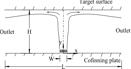
An illustration of the problem including the dimensions and nomenclature is shown in Fig. 1. A two-dimensional air jet with uniform velocity leaves the nozzle exit of width W and impinges onto a flat surface. Another confining plate is parallel to the impinged surface which is separated by the distance of H. Length of the channel is denoted by L and these two geometrical parameters are expressed in a dimensionless form as H/W and L/W. Assuming constant physical properties including density for air at standard atmospheric pressure and 20ºC, the jet Reynolds number, Re, is defined based on the exit velocity and nozzle width. Half of the domain is considered in computations assuming a symmetrical flow.
By assuming steady, two-dimensional, incompressible, and laminar air flow with constant physical properties and also neglecting the dissipation effect in the energy conservation equation, the governing equations are
+ = 0 (1)
+ = −1 + ʋ + (2)
+ = −1 + ʋ + (3)
JCARME M. Rahimi and M. Mortazaei Vol. 4, No. 1, Autumn 2014
92
Fig. 1.
Geometry of a two-dimensional confined jet.
The boundary conditions to be applied over the line segments surrounding the computational domain are as follows:
For 0 ≤ x ≤ W/2, y = 0;
u = 0, v = v0,p = 0,T = T0 (5)
For W/2 <x ≤ L/2, y = 0;
Confined jet:
u = 0, v = 0, p = pw, ∂T/∂y = 0 Unconfined jet:
∂u/∂y = 0, ∂v/∂y = 0, p = 0, ∂T/∂y = 0
(6)
For 0 ≤ x ≤ L/2, y = H; u = 0, v = 0, p = pw, T = T0+10
(7)
For 0 <y <H, x = L/2; ∂u/∂x = 0, ∂v/∂x = 0,p = 0, ∂T/∂x = 0
(8)
For 0 <y<H, x = 0; ∂v/∂x = 0, u = 0, ∂p/∂x = 0, ∂T/∂x= 0
(9)
With these sets of boundary conditions, the static pressure at both target and confining surfaces (pw) has to be specified. Based on
Tannehill et al. [11], for an arbitrary point located on a solid surface, as indicated in Fig. 2, Eq. (3) is reduced to
), = ), (10)
Fig. 2. Grid points for determining static pressure boundary condition.
This equation is approximated using first- and second-order accurate central difference approach as
, − ,
, − ,
= , − 2 , + ,
( , − , ) (11)
For this arbitrary point located on the wall, the continuity equation is also reduced to
), = 0 (12)
Substituting second-order central difference approximation of Eq. (12) for Eq. (11) results in
, = , −
2
, − ,
, (13)
A similar expression can be also obtained for the points located on the target surface.
3. Numerical procedure
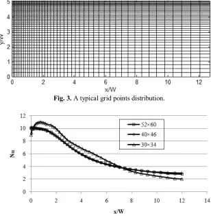
Figure 3 presents a typical grid points distribution which has clustering in both directions. The number of grid points is 46×40 in this figure and the clustering parameter has been set to produce more uniform variation in the grid distribution. Grid points are specified by two indexes (i and j) in the x and ydirections, respectively, and a global index is also calculated and assigned for each grid point as
H
W L
x y
Cofinning plate Target surface
93
= + ( − 1) × (14)
in which M is the maximum number of grid points in x direction.
Three unknowns, i.e. two velocity components and the static pressure for each grid point, are set orderly into an unknown vector array. A global coefficient matrix and a right-hand side vector array are also developed to form a set of linear algebraic equations. Three global indexes of3×ij-2, 3×ij-1,and 3×ij are used in the global coefficient matrix and right-hand side vector array to specify these physical parameters. The dimension of the square coefficient matrix is 3×M×Nwhich is a highly sparse matrix. Components of the coefficient matrix and the right-hand side vector array are determined using the governing equations for the internal grid points and based on the boundary conditions for the border points.
As an illustrative example, three unknowns for a grid point specified by i=1, j=2 and therefore ij=1+M which is located on the boundary of the domain are given by
( × )= 0
( × )− ( × ) = 0
× − × = 0
(15)
These three equations were used to specify the coefficients in (3×ij-2)th, (3×ij-1)th and (3×ij)th lines of the global coefficient matrix. For any arbitrary internal grid point specifying by indexes (i and j) and hence ij=i+(j-1)×M discretized forms of the continuity equation along with the x- and y-momentum equations were considered in the following forms to specify the components in the three relevant lines of the global coefficient matrix. All the terms in the governing equations were discretized using second order central-difference approximation. 1 2 , − , − + , − , − +1 2 , − , − + , − ,
− = 0
(16) +1 2 , , − , − + , − , − +1 2 , , − , − + , − , −
= − 1
2 , − , − + , − , − + 2ʋ − , − , − − , − , − + 2ʋ − , − , − − , − , − (17) 1 2 , , − , − + , − , − +1 2 , , − , − + , − , −
= −
1
2
,−
,−
+
,−
,−
+
2
−
,−
,−
−
,−
,−
+
2
−
,−
,−
−
,−
,−
(18)JCARME M. Rahimi and M. Mortazaei Vol. 4, No. 1, Autumn 2014
94
software. Velocity components obtained from each iterationare used in the next iteration until the solution is converged. The number of iterations is typically about 15, in which the variation of the velocity components is less 1% in the whole domain.
4. Results and discussion
4. 1. Unconfined jet
Based on a systematic grid resolution test, it was found that a closely spaced grid points with the spacing of about 0.2 mm was required to capture the sharp gradients in the vicinity of the target surface. As an instance and in order to present the effect of the grid refinement on the final results, Nusselt number distributions obtained for different grids are shown in Fig. 4. Accordingly, the results were affected by the
grid size; however, a compatible result was obtained using relatively fine grids.
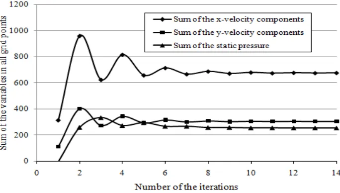
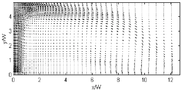
For grid points as indicated in Fig. 3 and for the jet Reynolds number of 250, the resulted velocity and static pressure distributions are shown in Figs. 5 and 6, respectively. These figures demonstrate that the jet was retarded by the solid wall at the stagnation region and a wall jet was developed parallel to the impinged surface. The entrainment fluid from the stagnant surroundings was also seen both in the impingement and in the wall jet regions. The static pressure variations were mainly restricted to the stagnation region and it was fairly constant and equal to the stagnant surrounding pressure far from this region. Figure 7 indicates the rate of convergence in this numerical procedure. It can be observed that the results converged after quite a few numbers of iterations.
Fig. 3. A typical grid points distribution.
95 Fig. 5. Velocity distribution, Re = 250, H/W = 5, unconfined jet.
Fig. 6. Static pressure distribution, Re = 250, H/W = 5, unconfined jet.
JCARME M. Rahimi and M. Mortazaei Vol. 4, No. 1, Autumn 2014
96
Using the velocity distribution, the energy equation was then solved and the temperature distribution was also obtained. Similar to the momentum equations, central difference approximation was used in all the terms in the energy conservation equation. The temperature distribution was then used to calculate the local heat transfer rate from the solid wall to the air flow. Wall pressure, friction and heat transfer coefficients were calculated using the following expressions
=
12 0
2
=
1 02 0
2
=
−
(
−
0)(19)
Variations of these parameters are shown in Fig. 8. In order to present these variations more briefly, Nusselt number was shrunk and the wall friction coefficient was magnified both 10 times from their actual values.
Fig. 8. Wall pressure, friction and heat transfer coefficients, Re = 250, H/W = 5, unconfined jet.
97 4. 2. Confined jet
The proposed numerical approach was then applied to a confined jet under the same geometrical configuration and for the same jet Reynolds number. Similar to Fig. 5, the velocity distribution is shown in Fig. 9. Unlike the unconfined jet, the entering flow into the main jet was quite restricted in this case. Figure 10 presents the static pressure distribution in which small disturbances no more existed in the flow field. Also, the region with sharp static pressure gradients was quite limited compared to the previous case.
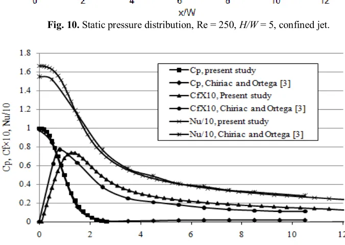
In order to examine the accuracy of the results, a comparison was made for the wall coefficients obtained from the present study and that of Chiriac and Ortega [3], as shown in Fig. 11. It can be observed in this figure that the main results were quite consistent and a reasonable accuracy would be preserved using the proposed numerical approach. The difference between the wall coefficients obtained for both confined and unconfined jets was also reasonable; but, it is not discussed here because of being beyond the scope of the present study.
Fig. 10. Static pressure distribution, Re = 250, H/W = 5, confined jet.
JCARME M. Rahimi and M. Mortazaei Vol. 4, No. 1, Autumn 2014
98
Fig. 12. Velocity distribution in a separated flow region, Re = 100, H/W = 5, confined jet.
Application of the proposed numerical approach is not restricted to the simple case which presented above; however, a variety of the flow patterns could be studied using this method. As a representative example, the jet Reynolds number was decreased to 100 where other geometrical and physical parameters were kept constant. Because of the wall fiction and the entering flow, the weak jet could not develop parallel to the solid wall; instead, a separated flow was established within the field. Such a flow field with the confining wall is shown in Fig. 12.
5. Conclusions
A novel numerical approach was proposed and applied for the jet impingement heat transfer analysis. This method was a straightforward, effective, and very clear method, in which no additional equation was developed for the pressure distribution. Employing this method, all terms in the conservation equations of mass and momentum were discretized using second-order accurate central difference approximation and then were applied for all the grid points located within a computational domain. Appropriate boundary conditions were then utilized for the grid points located on the boundaries of the domain. A complete set of algebraic equations was then formed combining
by two sets of the equations. Velocity components along with the static pressure were calculated using an iterative scheme. The convergence rate of the method was quite satisfactory so that a converged solution could be obtained after a few iterations. Two cases of unconfined and confined jets were investigated in the present study and the details of the flow and thermal fields were obtained. Wall coefficients obtained for the latter case were in reasonable agreement with the results of a similar study. It was also demonstrated that the proposed method could be applied in the analysis of more complicated flow fields.
References
[1] S. H. Seyedein, M. Hasan, and A. S. Mujumdar, “Modeling of a single confined turbulent slot jet impingement using various k-ε turbulence models”,
Applied Mathematical Modelling, Vol.
18, No. 10, pp. 526-537, (1994).
[2] Y. T. Yang and T. P. Hao, “Numerical studies of three turbulent slot jets with and without moving surface”,
ActaMechanica, Vol. 136, No. 2, pp.
17-27, (1999).
99 slot jet impinging on an isothermal
surface”, International Journal of Heat and Mass Transfer, Vol. 45, No. 6, pp. 1237-1248, (2002).
[4] T. H. Park, H. G. Choi, J. Y. Yoo and S. J. Kim, “Streamline upwind numerical simulation of two-dimensional confined impinging slot jets”, International
Journal of Heat and Mass Transfer, Vol.
46, No. 2, pp. 251-262, (2003).
[5] D. Sahoo and M. A. R. Sharif, “Numerical modeling of slot-jet impingement cooling of a constant heat flux surface confined by a parallel wall”,
International Journal of Thermal
sciences. Sci, Vol. 43, No. 9, pp. 877-887, (2004).
[6] E. Arquis, M. A. Rady and S. A. Nada, “A numerical investigation and parametric study of cooling an array of multiple protruding heat sources by a laminar slot air jet”, International
Journal of Heat and Fluid flow, Vol. 28,
No. 4, pp. 787-805, (2007).
[7] H. G. Lee, H. S. Yoon and M. Y. Ha, “A numerical investigation on the fluid flow
and heat transfer in the confined impinging slot jet in the low Reynolds number region for different channel heights”, International Journal of Heat and Mass Transfer, Vol. 51, No. 15, pp. 4055-4068, (2008).
[8] M. A. R. Sharif and A. Banerjee, “Numerical analysis of heat transfer due to confined slot-jet impingement on amoving plate”, Applied Thermal
Engineering, Vol. 29, No. 2, pp. 532-540,
(2009).
[9] B. N. Hewakandamby, “A numerical study of heat transfer performance of oscillatory impinging jets”, International
Journal of Heat and Mass Transfer, Vol.
52, No. 2, pp. 396-406, (2009).
[10] M. A. R. Sharif, “Heat transfer from an isothermally heated flat surface due to twin oblique slot- jet impingement”,
Procedia Engineering, Vol. 56, No. xx,
pp. 544-550, (2013).
[11] J. C. Tannehill, D. A. Anderson and R. H. Pletcher, Computational fluid
mechanics and heat transfer, 2nd ed.,