I
nternational
J
ournal of
Agriculture
and Biosciences
www.ijagbio.com; editor@ijagbio.com
Research Article
Development and Testing of a Double Ring Soil Infiltrometer
Ogbu KN, Nwachukwu CP, Orakwe LC and Chukwuma EC
Department of Agricultural and Bioresources Engineering, Nnamdi Azikiwe University, Awka, Nigeria *Corresponding author:
[email protected]
Article History: Received: August 12, 2015 Revised: November 20, 2015 Accepted: December 22, 2015
A B S T R A C T
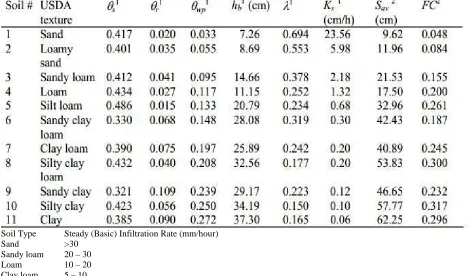
In this study, a standard double ring infiltrometer was designed, constructed and was used to determine the mean infiltration rate of the study site and to compare measured values with predicted values from a known infiltration model. The double ring was developed galvanized iron with the dimensions of 30cm height and 30cm and 60cm diameters for the inner and outer rings respectively following the FAO (1998) standard. The selected study site was the experimental farm of the department of Agricultural and Bioresources Engineering of Nnamdi Azikiwe University Awka. The site measures an area of 5227m2. Soil samples were collected from test holes 10 – 15cm deep, made at 20 – 30cm away from the installed rings prior to the test. The tests were carried out at nine locations uniformly spaced within the site. The collected samples were tested in the laboratory to determine the initial soil water content of each test location using the oven dry method, and also the soil type based on texture following the USDA Textural Triangle Classification. The measured field rates were validated using the Green and Ampt model which requires the values of the soil saturated hydraulic conductivity the moisture deficit , and the effective suction at the wetting front . The values for , were obtained in literature from the soil properties estimation by Rawls et al. (1982), according to soil texture. The soil textural class analysis for the site ranged from loamy sand to clay. The infiltration results which showed a lot of heterogeneity as observed from one location to location were: (Z11 = 1.13, Z12
= 55.00, Z21 = 1.00, Z22 = 4.24, Z31 = 11.00, Z32 = 5.66, Z41 = 27.12, Z42 = 9.90 and Z51 = 1.70)mm/hr. with a mean rate
of 13.00mm/hr. Likewise the calculated rates present the following values: (Z11 = 13.60, Z12 = 65.42, Z21 = 13.60, Z22 =
9.60, Z31 = 12.56, Z32 = 7.60, Z41 = 26.00, Z42 = 3.50 and Z51 = 4.10)mm/hr. with a mean rate of 17.33mm/hr. The both
mean rates thus presented fall into the class range of infiltration rates for loam soil type as given in literature and hence the site is inferred to be generally loam soil type. This soil type is relatively good for agricultural use as it has good capillary network, moderate pore spaces, good water retainability and moderate infiltratibility.
Key words:
INTRODUCTION
Plants form the major source of food for man and the primary producers in the food chain, hence its requirements for optimal growth and development raises a lot of concern for man of which water is chief. Water must be available to plants at the right amount and as at when due whether by natural precipitation or by irrigation. This however, is subject to the infiltration rate of the given soil which determine how much and how easily water will infiltrate the soil to replenish the soil moisture deficiency and the excess that goes to ground-water aquifers through seepage or deep percolation. Infiltration is important to any hydrological model as interception, depression storage evaporation, and the available precipitation input; for generating overland flows/runoff
(Mustafa and Yusuf, 2012). The infiltration rate denoted as which depends on the nature of the soil layer, initial moisture content, rainfall intensity, vegetal cover and slope of the ground surface. It is highest when water first enters the soil and gradually decreases with time until a constant rate is attained (Fedler et al., 2012). In many natural situations, the initial rate of water application such as rainfall or sprinkler irrigation rate is less than the potential final rate for a given soil. This implies a time lag in which water application rate will eventually exceed the soil infiltration rate resulting to ponding and possibly runoff.
Onwualu et al. (2006) defined infiltration as the process whereby water enters the surface strata of the soil and moves downward. Infiltration is further defined as the passage of water through the soil surface into the soil
(Gupta et al., 2008). When water is applied to the land surface either in form of rain or irrigation it enters the soil profile and replenishes the soil moisture deficiency and then the remaining portion moves down and becomes ground water. The surface intake (infiltration) determines the relation between water absorption and runoff. The sub-surface percolation rate determines the internal profile drainage, which is necessary for crop production (Onwualu et al., 2006).The term infiltration is generally used when considering level surfaces. Whenever the configuration of the soil surface influences the rate of the water entry the term intake rate is rather used (Onwualu et al., 2006). The process of infiltration has been widely studied and represents an important mechanism for movement of water into the soil under gravity and capillarity forces. Infiltration volume is subtracted from a precipitation event in order to determine net volume of rainfall, or rainfall excess, which is equivalent to the direct runoff from a watershed area (Philip et al., 2008). Horton (1933) showed that water infiltrates the surface soils at a rate that generally decreases with time. The rate of infiltration depends in a complex way on rainfall intensity, soil type, surface condition, and vegetal cover (Philip et al., 2008). If the rainfall intensity however is less than the infiltration capacity of the soil, no surface runoff occurs and the infiltration rate equals the rainfall intensity (Horton, 1933), otherwise, infiltration rate equals infiltration capacity.
Theory of infiltration
The hydrological cycle is unending and without a beginning point. In nature, water is in continuous motion and moves from one stage to another. The first stage of water may be assumed at any stage. If we assume it to be at evaporation from the oceans and other surfaces; vapors are transported by the moving air masses. Under favorable conditions, the vapor condense to form clouds, which fall upon the earth in different forms such as; rainfall, snowfall, hails, e.t.c. Precipitation majorly is in the form of rainfall or snowfall. In the tropical areas, precipitation is mainly rainfall.
An extensive study on infiltration as reported by Onwualu et al. (2006) was carried using a weighable laboratory showed that for any soil under constant rainfall, infiltration rate decreases in accordance with the relation (Onwualu et al., 2006);
Where; f = infiltration rate at any time t (mm/hr); fc = infiltration capacity at large value of t (mm/h); µ =( fo fc )= initial infiltration capacity at t = 0 (mm/h); t = time from beginning of rainfall (mm); k = constant for a particular soil and surface texture, e.g; if vegetation is present, (k) is small, while for a smoother surface texture (fo ) and ( fc ) are functions of both soil type and cover usually, a bare sandy or gravel soil will have high values of (fo ) and (fc ) but both values will increase for both soils if they are covered with vegetation. The coefficient (fc ) is a function of slope up to a limiting value of slope (ranging between 16% and 24%) after which there is little variation (Onwualu et al., 2006). fc is a function of initial moisture content: the drier the soil initially, the larger will be (fc )
and likewise the function of rainfall intensity if the intensity increases, (fc ) increases, this parameter has a greater effect on (fc ) than any other variable.
The method of flooding uses infiltrometers to measure the maximum rate at which water applied at the surface can pass downwards to the lower horizons. Onwualu et al. (2006) and Ali (2010) described infiltrometer as a device used to measure the rate of water intake of a given soil or other porous media. There are many types of infiltrometers but the commonly used are the single or double-ring infiltrometers. The double ring infiltrometer is very similar to the single ring type except for the number of rings involved. The concentric (double) ring infiltrometer however, is considered better for it ability to limit lateral movement of water from the inner ring hence providing a more reliable result. The double ring infiltrometer is a way of measuring saturated hydraulic conductivity of the surface layer. The rings are driven a few centimeters into the soil to prevent leakage (Ringman, 1994) cited by (Obeta 2012). Each ring is supplied with a constant head of water either manually or from mariotte tubes. Hydraulic conductivity can be estimated for the soil when the water flow rate in the inner ring is at a steady state.
It works by directing water onto a known surface area determined by parameters of the inner ring. The rate of infiltration is determined by the amount of water that infiltrates into the soil per surface area, per unit of time.
Green and ampt model
Richards equation takes the form;
1.1
Where;
= Volumetric moisture content (cm3/cm3) = Distance below the surface (cm)
= Capillary suction (pressure) (cm of water) = Unsaturated hydraulic conductivity (cm/s) The unsaturated hydraulic conductivity k(θ) can be substituted into Darcy’s law.
q=-k 1.2
Where;
=Darcy velocity (cm/s) =depth below surface (cm) =potential or head= (cm)
= Suction (negative cm)
(θ)=Unsaturated hydraulic conductivity (cm/s) θ=Volumetric moisture content.
Equation (2.12) is then applied as an approximation to the saturated conditions between the soil surface ( ) and the wetting front (“wf”),
1.3
Using the average capillary suction at the wetting front Ψ; we have:
Noting that h=0 at the surface. Eq.(2. 13) becomes
1.5
1.6 The volume of infiltration down to the depth L is given by;
1.7 Substituting for L in Eq.(2.15) gives the original form of
the Green-Ampt equation; (Philip et al., 2008)
) 1.8
MATERIALS AND METHODS
Study area
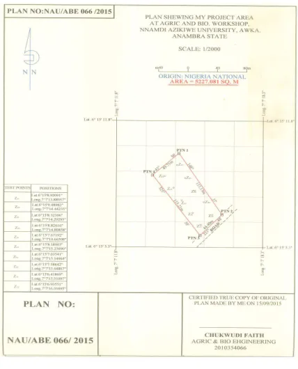
The infiltration tests were performed at the experimental farm plot of the Department of Agricultural and Bioresources Engineering, Nnamdi Azikiwe University (NAU) Awka. It is typical of a savanna covered with grass. The site measures a total of 5227.08 square meters. Figure 2.1, shows map of the site. The plot was divided into nine (9) uniformly spaced sections namely; z11 z12, z21, z22 z31 z32, z41 z42 and z51 following a
recommended sampling density of two sampling per 10,000ft2 (929m2) for large infiltration area (ASTM, 2003). The infiltrometer was hammered into the soil to a minimum depth of 15 cm and the piece of flat board was used to protect the rings from damaging during hammering. The level was used to achieve a uniform level of the ring height. The depth gages were installed, and located near the center of the inner ring and midway between the two rings. Water was poured into the ring until the depth was approximately 13cm. At the same time, water was added quickly to the space between the two rings to the same depth. The water within the two rings was to prevent a lateral spread of water from the infiltrometer. The soil surface within the center ring and between the two rings was covered with splash guards to prevent erosion of the soil when the initial liquid supply was poured into the rings. After 5-7 minutes, there was drop in water level in the inner ring on the measuring rod which was noted, more water was added to bring the level at the start of the test. The starting time and the initial water level on the measuring rod were recorded. The water level outside the ring was maintained similar to the inner ring throughout the test. The test was continued until the drop in water level was the same over the same time interval. Readings were taken frequently at 15 minutes interval at the beginning of the test, and was later extended to 30 minutes intervals. The experimental time lasted for 150 minutes. The top of the rings was covered while no reading was been taken to prevent evaporation, and to protect the test apparatus and fluid from direct sunlight and temperature variations that are large enough to affect the slow measurements significantly. At each test location, soil sample was collected at a depth of 15cm and was used in the determination of initial water content and soil textural class in the laboratory. The samples were collected by hand from holes made at a horizontal distance of 20-30cm from the installed rings. Samples were wrapped and made air tight to avoid loss or gain of moisture which may bias the laboratory result.
Required measurements
Measured infiltration rates from the infiltrometer, was compared with calculated result from an infiltration model, the Green Ampt equation was used. The equation
Fig. 1: Location of experimental sample points in the farm.
Fig. 2: USDA Soil Textural Triangle (source: en.wikipedia.org)
requirement obtained by measurement was the initial soil water content. The hydraulic conductivity and the suction head were obtained from literature due to the difficulty and high cost of conducting direct measurements for these parameters.
Laboratory Testing and Determination of Parameters The procedure for the soil texture test is outlined in below, and the USDA textural triangle (Fig. 2.2) was used to classify the samples.
Procedure
(1) Soil sample was obtained from a depth of 15cm. 3 of such soil samples collected from A, B and C zones were combined, as the soil may be different in different spots.
(3) The sample was diluted by adding 1 jug of water. (4) ½ teaspoon of dishwashing detergent was added. (5) The bucket content was stirred vigorously with hand
to break lumps.
(6) The content of the bucket was poured into a sedimentary glass column.
(7) The mixture was allowed to stand in a sedimentation glass column for exactly 30 seconds. Measuring and recording the height in centimetre of the soil particles that have settled at this time was done. This is the sand portion.
(8) After the next 30 minutes. The height in the centimetre of the soil particles that have settled at this time was measured and recorded. The value was subtracted from the first (30 seconds) reading. This difference is the portion of soil that is silt.
(9) Now the measure column of soil was allowed to stand for at least 24-hour point, for another reading. Subtracting the height at the 30 minute reading. This difference is the clay portion of the soil. Then, the three height readings were converted in the form of percentages.
Initial volumetric soil water content and bulk density Gravimetric soil water content was determined by the following equation (Gardner, 1986):
2.1
The results obtained were converted to percentages by:
2.2
Where;
MC = moisture content
m1 = mass of wet soil
m2 = mass of dry soil
Validation of result using the green and ampt equation In order to validate the infiltration rate from the developed infiltrometer, the Green-Ampt equation (Philip et al., 2008) was used and is given thus:
2.3
Where;
=Infiltration rate; [cm/hr], =Moisture deficit,
=Cumulative infiltration; [cm]
=Saturated hydraulic conductivity; [cm/hr], =effective suction at the wetting front; [cm]
RESULTS
Data analysis
The steady state infiltration rates for the different sampled locations are as shown in table 3.2.
Therefore, the mean infiltration rate (f) is calculated thus;
= 13mm/hr
Graphical Data Representation Using the Green and Ampt Model
The infiltration rate was calculated by the Green and Ampt model which is given by;
)
Infiltration rate calculated for test location Z11
(Soil Type: Clay)
= 0.06(cm/h); = ( ) = (0.385 – 0.185) = 0.20
and , 0.575cm
1.36cm/hr (13.60mm/hr)
Infiltration rate calculated for test location Z12
(Soil Type: Loamy sand)
5.98(cm/h); = ( ) = (0.401 – 0.035) = 0.366
and , 46.55cm
6.54cm/hr (65.40mm/hr)
Infiltration rate calculated for test location Z21
(Soil Type: Clay)
= 0.06(cm/h); = ( ) = (0.385 – 0.090) = 0.295
and , 0.85cm
1.36cm/hr (13.60mm/hr)
Infiltration rate calculated for test location Z22
(Soil Type: Clay)
= 0.06(cm/h); = ( ) = (0.385 – 0.090) = 0.295
and , 1.22cm
0.96cm/hr (9.60mm/hr)
Infiltration rate calculated for test location Z31
(Soil Type: Silt loam)
= 0.68(cm/h); = ( ) = (0.486 – 0.135) = 0.334
and , 13cm
1.26cm/hr (12.60mm/hr)
Infiltration rate calculated for test location Z32
(Soil Type: Sandy clay)
= 0.30(cm/h); = ( ) = (0.330 – 0.146) = 0.184
and , 5.09cm
0.76cm/hr (7.60mm/hr)
Infiltration Rate Calculated For Test Location Z41
(Soil Type: Sandy loam)
= 2.18(cm/h); = ( ) = (0.412 – 0.142) = 0.27
and , 30cm
2.6cm/hr (26.00mm/hr)
Infiltration Rate Calculated For Test Location Z42
(Soil Type: Clay loam)
= 0.2(cm/h); = ( ) = (0.390 – 0.150) = 0.24
and , 12.9cm
0.35cm/hr (3.50mm/hr)
Infiltration Rate Calculated For Test Location Z51
(Soil Type: Clay)
= 0.06(cm/h); = ( ) = (0.385 – 0.170) = 0.22
and , 2.3cm
0.41cm/hr (4.10mm/hr)
Therefore, the mean calculated infiltration rate (f) becomes;
Table 1: Infiltration rates of the study area
Elapsed Time (min)
Infiltration rate (mm)
(Z11)
Infiltration rate (mm)(Z12)
Infiltration rate (mm)
(Z21)
Infiltration rate (mm)
(Z22)
Infiltration rate (mm)
(Z31)
Infiltration rate (mm)
(Z32)
Infiltration rate (mm)
(Z41)
Infiltration rate (mm)
(Z42)
Infiltration rate (mm)
(Z51)
15 5.66 85.48 6.00 7.64 26.60 9.06 65.64 40.16 6.22 30 4.53 75.00 5.64 5.66 24.5 8.77 63.92 22.08 5.40 45 3.40 70.00 5.64 5.00 23.48 8.20 53.20 19.01 3.50 60 2.56 65.00 4.52 4.75 22.06 7.36 35.92 17.30 2.50 90 1.13 60.00 2.02 4.44 11.88 6.24 27.16 10.74 2.00 120 1.13 55.00 2.00 4.24 11.00 5.66 27.01 9.9 1.70 150 1.13 55.00 2.00 4.24 11.00 5.66 27.01 9.9 1.70
Table 2: Steady State Infiltration Rates of the Tested Locations
Location Z11 Z12 Z21 Z22 Z31 Z32 Z41 Z42 Z51
Steady state infiltration rate (mm/hr) 1.13 55.00 1.00 4.24 11.00 5.66 27.12 9.9 1.70
Table 3: Average Infiltration Rate
Time interval (min)
Summation of Infiltrations (mm) of all Locations per Interval Average Infiltration rate(mm/min) Z11 Z12 Z21 Z22 Z31 Z32 Z41 Z42 Z51
15 1.42 21.37 1.50 1.91 6.65 2.27 16.42 10.04 1.56 7.02/9=0.47 15 1.13 18.75 1.41 1.41 6.13 2.19 15.98 5.52 1.35 5.99/9=0.40 15 0.85 17.50 1.41 1.25 5.80 2.05 13.30 4.75 0.88 5.31/9=0.35 15 0.64 16.25 1.13 1.19 5.52 1.84 8.98 4.33 0.63 4.00/9=0.27 30 0.57 30.00 1.01 2.22 5.94 3.12 13.58 5.37 1.00 6.98/9=0.23 30 0.57 27.50 1.00 2.12 5.50 2.83 13.50 4.95 0.85 6.54/9=0.22 30 0.57 27.50 1.00 2.12 5.50 2.83 13.50 4.95 0.85 6.54/9=0.22
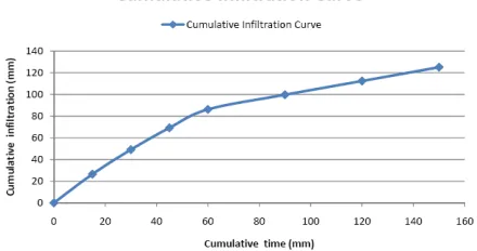
Table 4: Average Site Cumulative Infiltration
Cumulative
Time (Min) Cumulative Infiltration for the Tested Locations
Average rate (mm) 15 (1.42 + 85.48 + 1.50 + 1.91 + 26.60 + 9.06 + 65.64 + 40.16 + 6.22) = (237.99) 9 26.44 30 (2.55 + 160.48 + 2.97 + 3.32 + 51.10 + 17.83 + 129.56 + 62.24 + 11.62) = (49.07) 9 49.07 45 (3.40 + 230.48 + 4.32 + 4.57 + 74.58 + 26.03 + 182.76 + 81.25 + 15.12) = (622.51) 9 69.17 60 (4.04 + 295.48 + 5.45 + 5.76 + 96.64 + 33.39 + 218.68 + 98.55 + 17.62) = (775.61) 9 86.18 90 (4.61 + 355.48 + 6.46 + 7.98 + 108.52 + 39.63 + 245.84 + 109.29 + 19.62) = (897.43) 9 99.71 120 (5.18 + 410.48 + 7.46 + 10.10 + 119.52 + 45.29 + 272.85 + 119.19 + 21.32) = (1011.39) 9 112.38 150 (5.75 + 465.48 + 8.46 + 12.22 + 130.52 + 50.95 + 300.05 + 129.09 + 23.01) = (1125.53) 9 125.06
Table 3.10: Steady (Basic) Infiltration Rates for Different Soil Types
Soil Type Steady (Basic) Infiltration Rate (mm/hour) Sand >30
Fig 3: Plot of infiltration against time for Z11
Fig 4: Plot of infiltration rate against time for Z12
Fig 5: Plot of infiltration rate against time for Z21
Fig 6: Plot of infiltration against time for Z22
Fig 7: Plot of infiltration against time for Z31
Fig. 8: Plot of infiltration against time for Z32
Fig 9: Plot of infiltration against time for Z41
Fig 10: Plot of infiltration against time for Z42
Fig 11: Plot of infiltration against time for Z51
Fig. 13: Average Cumulative Infiltration Curve of the Study Site
Fig. 14: Average Infiltration Curve of the Site
DISCUSSION
The steady state infiltration rate as obtained from the field measurement is given approximately as 13mm/hr which shows the site to be generally loam soil type from table 4.15. This value also suggests that the precipitation input for this field should not exceed 13mm/hr beyond which it will produce runoff.
However, the average value as calculated from the Green and Ampt model was obtained to be 17.33mm/hr.
The result thus presented shows some variability which may be attributed to the influence of so many factors affecting infiltration rate which are ignored or could not be simulated by the model. They include compaction; which may be due to intense rainfall as the experiment was carried out during the peak of rains (August-September), or as a result of repeatedly using heavy equipment on the site, such as the departmental tractor, which forms a hardened and a compacted layer below the topsoil called a plowpan. This condition greatly reduces the ability of the soil to infiltrate water. Also communication with the personnel that installed the site gate did reveal that standing water was observed at less than two feet depth, hence causing high degree of soil wetness which impedes infiltration.
Again, likely is the possibility that air counter-flow reduced infiltration rate. The downward movement of water that enters the soil compresses the air; the air under pressure in turn offers a resistance to the movement of water. This effect is more marked in areas where the ground is nearly horizontal (Gupta et al., 2008) such as in our farm plot.
The soil structure which determines the soil layer permeability greatly affects the rate of infiltration. Though
infiltration at first is generally high and gradually reduces to a constant rate; during the test, it was observed that the initial rate was very low and then increased with time, a situation which shows that the shallow sediments are less permeable than the deeper sediments and hence controls the infiltration rate. Likewise, almost all soils except pure sand have colloids which swell on hydration, resulting to reduction in infiltration.
Conclusion
A method of investigation of soil infiltration rate using a double ring infiltrometer was developed. The double ring infiltrometer was designed, developed and tested and the measured rates were found to be close to those predicted by the approximate model used.
A purely physically based infiltration model, the Green and Ampt model was used to validate the results obtained from the field measured rates. This model was preferred as it requires no measured infiltration data, and has shown to be more versatile, as it can be applied validly under non-ponded conditions and also with variety of non-homogeneous soil profiles.
The study site was the Nnamdi Azikiwe University Agricultural and Bioresources Engineering Departmental Experimental Farm. Data was collected from nine uniformly spaced test locations, and the steady state infiltration rate was observed to be 13mm/hr.
The USDA Textural Triangle was used to determine the soil type of the site which showed a lot of heterogeneity from one location to another ranging from Loamy sand to Clay and likewise in the soil structure from layer to layer through the soil profile of the site. However, the steady state infiltration rate shows the site to be generally Loam (see table 4.15).
The infiltration rates therefore were representative of the deeper sediments, the head applied was 13mm to 15mm, the time of application ranged from 15min. to 30min. intervals, and the minimum rather than the maximum rate of infiltration were the ones used. Considering all factors, a specific infiltration rate for a particular type of sediment is virtually nonexistent and so measured rates are primarily of comparative value (Musgrave and Free, 1937).
This test method will be found useful in field measurements of the infiltration rates of soils. Infiltration rates have application to such studies as liquid waste disposal, evaluation of potential septic-tank disposal fields, leaching and drainage efficiencies, irrigation requirements, water spreading and recharge, canal or reservoir leakage, and watershed management. Flood, erosion and transport of pollutants can be predicted based on runoff rate which is directly affected by infiltration rate. Hence understanding infiltration relationship with surface conditions and enhancing soil infiltration ability of agricultural fields while sustaining the soil structure and fertility are very imperative.
REFERENCES
Ali MH, 2010. Fundamentals of irrigation and on-farm water management: v. 1:141. Springer Publishing Company Inc.
ASCE, 1996. American Society of Civil Engineers, Task Committee on Hydology Handbook. Reports on engineering practices: No. 28, Hydrology Handbook, New York.
ASTM, 2003. Standard test method for infiltration rate of soils in field using a double-ring infiltrometer: Agricultural research Service Publication, 4: 5. Beven KJ, 2000. Rainfall-runoff modeling. The Primer,
John Wiley and Sons Ltd, New York.
Croley TE and C He, 2005. Great lakes spatial distributed watershed model of water and materials runoff. Proceedings; International Conference on Poyang Lake Wetland Ecological Environment. Jiangxi Normal University, China.
FAO, 1998 (Food and Agricultural Organisation). www.fao.org
Fedler CB, J Littlejohn, R Duna and Li Feng, 2012. Refining the application rates for on-site surface application. Civil and Environmental Engineering Department, Texas Tech University, Lubbock. Garen DC and DS Moore, 2005. Curve number hydrology
in water quality modeling: uses, abuses, and future directions, Journal of the Am. Water Resou. Association, 41: 377-388.
Gupta BL and Amit Gupta, 2008. Water Resources Systems and Management. Stand and Publishers Distributors, Delhi.
Holland JM, 2004. The environmental consequences of adopting conservation tillage in Europe: reviewing the evidence. Agriculture Ecosystems and the Environment, 103: 1-25.
Horton RR, 1933. The role of infiltration in the hydrological cycle: Am. Geophys. Union Trans., 14th ann. Mtg., pp: 446-460.
Johnson AI, 1963. A field method for measurement of infiltration: Geological Survey Water Supply Paper, United States Government Printing Office, Washington. Lewis MR, 1937. The rate of infiltration of water in
irrigation practice. Eos, Trans. AGU, v.18:361-368 Majumdar DK, 2000. Irrigation water management:
Principles and practice. Prentice Hall of India private limited, New Delhi.
Map data © 2015. www.google.com
Musgrave GW and GR Free, 1937. Preliminary report on a determination of comparative infiltration rates on some major soil-types: Am. Geophys. Union Trans., 18: 345-349.
Mustafa S and MI Yusuf, 2012. Infiltration: A Textbook of Hydrology and Water Resources. Tops merit Page Publishers, Abuja, Nigeria, pp: 40-52.
Obeta MC, 2012. Infiltration: Fundamentals of Hydrology. Chuka Educational Publishers, Nsukka, Nigeria.
Onwualu AP, CO Akubuo and IE Ahaneku, 2006. Fundamentals of Engineering for Agriculture. Immaculate publications limited, Enugu.
Oram B, 2005. Hydrological Cycle. Watershed Assessment, Education, Training, Monitoring Resources in Northeastern Pennsylvania. Wilkes University. Environmental Engineering and Earth Sciences Department. Wilkes-Barre.
Philip BB, CH Wayne and EV Baxter, 2008. Hydrology and Flood Plain Analysis. Prentice Hall Inc. USA., pp: 65-79.
Rawls WJ, DL Brakensiek and KE Saxton, 1982. Estimation of soil water properties. Transactions of the Asae, 25:1316-1320.
Shukla MK and R Lal, 2006. Water infiltration in soil. The Ohio State University, Columbus Ohio. Encyclopedia of Soil Science.
Soil Science Society of American, 1975. Glossary of Soil Science Terms: Madison, Wisconsin, Soil Society of America. Prentice-Hall, Englewood Cliffs, New Jeresy.
Sonaje NP, 2013. Modeling of infiltration process – a review. Indian Journal of Applied Research 9: 226-230.
Sparovek G, QD Vanlier, S Marciniconis, J Rogasic and E Schnng, 2002. A Simple model to Predict river floods – a contribution towards quantifying the significance of soil infiltration rates. Landbauforschung volkenrode, 52:187-194.
Swartzendruber D, 1993. Revised attribute of the power form infiltration equation. Water resources 29: 2455-2456.