Available Online at www.ijpret.com 600
INTERNATIONAL JOURNAL OF PURE AND
APPLIED RESEARCH IN ENGINEERING
AND TECHNOLOGY
A PATH FOR HORIZING YOUR INNOVATIVE WORK
HOME BASED ENERGY SAVING SYSTEM BY IMAGE PROCESSING
PRATIK G. TALEY, DR. GAJANAN P.DHOK
1. Student, Sipna College of Engineering, Amravati, Maharashtra, India.
2. Head of Department, Sipna College of Engineering, Amravati, Maharashtra, India
Accepted Date: 15/03/2016; Published Date: 01/05/2016
\
Abstract- Image and video processing play an important role in the development of technologies for
dealing with security issues: surveillance cameras are widely diffused as means of crime reduction, and image analysis tools are used in the forensics field. Lately, the interest in advanced video-based surveillance applications has been increasing. This is especially true in the field of urban railway transport where video-based surveillance can be exploited to face many relevant security aspects (e.g. vandalism, overcrowding, abandoned object detection etc.). The aims at investigating an open problem in the implementation of video-based surveillance systems for transport applications, i.e., the implementation of reliable image understanding modules in order to recognize dangerous situations with reduced false alarm and mis detection rates. Emerging trends in video surveillance applications. Detection and tracking of moving objects is important in the analysis of video data and higher level security assessment. Image registration plays a key role in designing video surveillance system. The purpose of image registration in surveillance application is to geometrically align two or more images to enable in-depth data analysis such as feature detection, or motion sensing. Image registration is especially necessary to compare and integrate image data that comes from different sources times.
Keywords:-Image Processing, Energy Saving System
Corresponding Author: MR. PRATIK G. TALEY Access Online On:
www.ijpret.com
How to Cite This Article:
Pratik G. Taley, IJPRET, 2016; Volume 4 (9): 600-614
Available Online at www.ijpret.com 601
INTRODUCTION
Video surveillance systems are widespread and common in many environments. Video surveillance has been a key component in ensuring security at airports, banks, casinos, and correctional institutions. More recently, governments’ agencies, businesses, and even schools are turning toward video surveillance as a means to increase public security. With the proliferation of inexpensive cameras and the availability of high-speed, broad-band wireless networks, deploying a large number of cameras for security surveillance has become economically and technically feasible. Several important research questions remain to be addressed before we can rely upon video surveillance as an effective tool for crime prevention, crime resolution, and crime protection. Much of the current research in video surveillance focuses on algorithms to analyze video and other media from multiple sources to automatically detect significant events. Example applications include intrusion detection, activity monitoring, and pedestrian counting. The capability of extracting moving objects from a video sequence is a fundamental and crucial problem of these vision systems. For systems using static cameras, background subtraction is the method typically used to segment moving regions in the image sequences, by comparing each frame to a model of the scene background.
1. LITERATURE VIEW OF PROJECT
We searched if this kind of system is available or not, research work is going on this project like ,Lockheed Martin and the university of Central Florida (UCF) are jointly investigating the use of a network of COTS video cameras and computers for a variety of security and surveillance operations. The Three main novel aspects of the network presented in this paper are-
i)The integration of automatic target detection and recognition techniques with tracking.
ii)The handover and seamless tracking of objects across a network.
iii) The development of real-Time communication and messaging protocols using COTS networking components.
The approach averages the previously developed KNIGHT human detection and tracking system developed by UCF, and Lockheed Martin’s automatic target detection and recognition (ATD/R)algorithms. The work presented in this paper builds on these capabilities for surveillance using stationary sensors, with the goal of subsequently addressing the problem of moving platforms.
Available Online at www.ijpret.com 602
2. PROJECT OVERVIEW
To track objects successfully in multiple cameras, one need to establish correspondence between objects detected and tracked in each camera.
Our system is able to discover spatial relationships between the camera FOVs and use this information to correspond between different perspective views of the same person. We employ a novel approach of finding the limits of FOV of a camera as visible in the other cameras that is very fast compared to conventional camera calibration based approaches. Using this information, when a person is seen in one camera, we are able to predict all the other cameras in which this person will be visible. Moreover, we apply the FOV constraint to disambiguate between possible candidates for correspondence. When tracking is initiated, there is no information provided about the FOV lines of the cameras. The system can, however find this information by observing motion in the environment. whenever there is an object entering or existing one camera, it actually lies on the FOV line of this camera in all other ones in which it is visible suppose that there is only one target .Then, when it enters the FOV of new camera, we find one constraint on the associated line. To such constraints will define the line and all constraints after that can be used in a least square formulation. In an earlier paper, it was demonstrated that the initialization of FOV lines by one person walking in the environment for about 40 seconds was sufficient to initialize the lines.
These lines were then used to resolve the correspondence problem between the cameras. However it is not always possible to have only one target moving in the scene. When multiple targets are in the scene and if one crosses the edge of FOV, all targets in the other cameras are picked as being candidates for the projection of FOV line.
Since the false candidates are randomly spread on both sides of the line whereas the correct candidates are clustered on a single line, correct correspondence will yield a line in a single orientation, but the wrong correspondence will yield lines in scattered orientation. We can then use Hough transform to find the best line in this case. This method needs more points for reliable estimate of the lines and therefore takes longer time to set up correctly. Additional constraints derived from categorization of objects and their motion may be used to reduce the number of false correspondence, thus reducing the time it requires to establish the lines.
3. Description
Available Online at www.ijpret.com 603
image and subtracts it from the background image after this convert the resultant image into gray scale image. If there are smashes it will perform filtering and remove it. Find the area that sort out biggest object in the image using area value and finally find out in which zone centered is presented and according switch on corresponding relay.
4. PHOTO VIEW OF PROJECT
Available Online at www.ijpret.com 604
Fig. No.2 Detection of the object
5.1Detection
The main difficulties of such approach lie in the fact that, even in controlled environment, the background undergoes a continual change, mostly use to the existence of lighting variations and distracters (example : clouds passing by, braches of trees moving with the wind). The robustness towards lighting variation of the scene is achieved using adaptive background models and adaptive per-pixel thresholds.
Detection is done on the basis of centroid of object is present. In detection, the image is acquired then it can compare with database if it matched with database no change will occur that’s why relay will not be operated. When the image is not matched there is a change because of that relay will be operated and finally we get output.
5.2How centroid is calculated?
The image is detected on the basis of maximum area. The maximum area is calculated depends upon number of pixels present in image. Maximum area is set by the designer according to their requirement. Number of frames is calculated per second when background is removed, then the centroid is calculated by maximum area that is maximum number of pixel in the image. The calculation of centroid is required for detection and tracking purpose.
If we set maximum area of the region for image detection for example 200 then the big image is detected relay is in on position and smaller image is not detected such as insects etc then relay is remain in off position thus energy is saved.
5.3Tracking
Available Online at www.ijpret.com 605
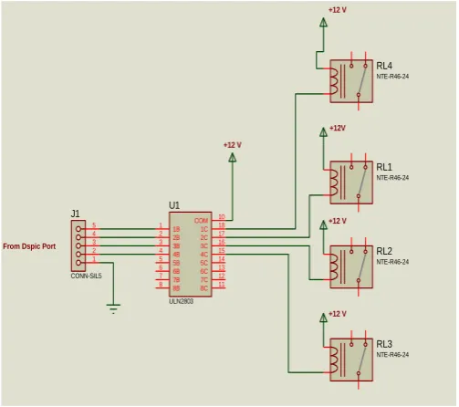
Fig No.3 Hardware description 5.4 ULN 2803
The eight NPN Darlington connected transistors in this family of arrays are ideally suited for interfacing between low logic level digital circuitry (such as TTL, CMOS or PMOS/NMOS) and the higher current/voltage requirements of lamps, relays, printer hammers or other similar loads for a broad range of computer, industrial, and consumer applications. All devices feature open–collector outputs and freewheeling clamp diodes for transient suppression.
The ULN2803 is designed to be compatible with standard TTL families while the ULN2804 is optimized for 6 to 15 volt high level CMOS or PMOS.
1B 1 2B 2 3B 3 4B 4 5B 5 6B 6 7B 7 8B 8 1C 18 2C 17 3C 16 4C 15 5C 14 6C 13 7C 12 8C 11 COM 10 U1 ULN2803 RL1 NTE-R46-24 RL2 NTE-R46-24 RL3 NTE-R46-24 RL4 NTE-R46-24 1 2 3 4 5 J1 CONN-SIL5 +12 V
From Dspic Port
+12V
+12 V
Available Online at www.ijpret.com 606
5. General Description
The LM78XX series of three terminal regulators is available with several fixed output voltages making them useful in a wide range of applications One of these is local on card regulation eliminating the distribution problems associated with single point regulation The voltages available allow these regulators to be used in logic systems instrumentation Hi-Fi and other solid state electronic equipment Although designed primarily as fixed voltage regulators these devices can be used with external components to obtain adjustable voltages and currents The LM78XX series is available in an aluminum TO-3 package which will allow over 10A load current if adequate heat sinking is provided Current limiting is included to limit the peak output current to a safe value Safe area protection for the output transistor is provided to limit internal power dissipation If internal power dissipation becomes too high for the heat sinking provided the thermal shutdown circuit takes over preventing the IC from overheating Considerable effort was expanded to make the LM78XX series of regulators easy to use and minimize the number of external components It is not necessary to bypass the output although this does improve transient response Input bypassing is needed only if the regulator is located far from the filter capacitor of the power supply
For output voltage other than 5V, 12V and 15V the LM117 series provides an output voltage range from 12V-57V.
6. Features
Output current in excess of 1A
Internal thermal overload protection
No external components required
Output transistor safe area protection
Internal short circuit current limit
Available in the aluminum TO-3 package
7.1 Parallel port
Less commonly referred to as the Centronics interface or Centronics connector after
the company that originally designed it, the port was later developed by Epson. The
parallel port is found on the back of IBM compatible computers and is a 25-pin (type
an example of the DB25 interface found on the back of the computer.
Available Online at www.ijpret.com 607
Fig.No.4 Parallel port
7. Identifying
In the above graphic of a parallel port you can notice the DB25 parallel port connection is easy to identify and is often the biggest connection on the back of the computer. The
connection is in the shape of the letter D, is a female connector, and has 25 pins.
8. Additional technical information
The DB25 connector has an 8-bit data bus, supported a maximum cable length of 15 feet; although there are 50 foot cables, it is not recommended that these cables be used as it can create poor connection and data signals. Below is additional information about each of the pins on this connector. Pin 1 through 25 identified in the image above.
PIN PURPOSE
Pin 1 -Strobe
Pin 2 +Data Bit 0
Pin 3 +Data Bit 1
Pin 4 +Data Bit 2
Pin 5 +Data Bit 3
Pin 6 +Data Bit 4
Pin 7 +Data Bit 5
Pin 8 +Data Bit 6
Pin 9 +Data Bit 7
Pin 10 -Acknowledge
Pin 11 +Busy
Pin 12 +Paper End
Pin 13 +Select
Pin 14 -Auto Feed
Pin 15 -Error
Pin 16 -Initialize Printer
Pin 17 -Select Input
Available Online at www.ijpret.com 608
Pin 19 -Data Bit 1 Return (GND)
Pin 20 -Data Bit 2 Return (GND)
Pin 21 -Data Bit 3 Return (GND)
Pin 22 -Data Bit 4 Return (GND)
Pin 23 -Data Bit 5 Return (GND)
Pin 24 -Data Bit 6 Return (GND)
Pin 25 -Data Bit 7 Return (GND)
Below is an explanation of each of the above purposes.
Pin1 = Data acknowledgement when the signal is low.
Pin 2 - 9 = Data transfer pins.
Pin 10 = Acknowledge that the data has finished processing and when the signal is high
indicates ready for more.
Pin 11 = When the signal goes high indicate that the printer has accepted the data and is processing it. Once this signal goes low and Pin 10 goes high will accept additional data. Pin 12 = Printer paper jam when signal is high or no signal if printer jam. Pin 13 = When high signal printer is indicating that it is on-line and ready to print. Pin 14 = When low signal PC has indicated that the printer inset a line feed after each line. Pin 15 = Printer sends data to the computer telling it that an error has occurred. Pin 16 = When low signal PC has requested that the printer initiate an internal reset. Pin 17 = When low signal the PC has selected the printer and should in return prepare for
data being sent.
Pin 18 - 25 = Ground.
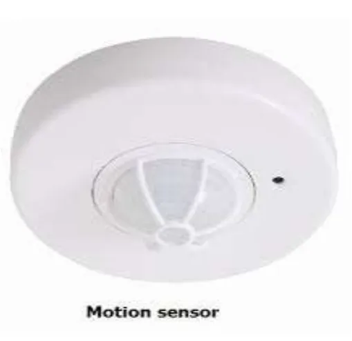
9. Working of Motion Sensors
Available Online at www.ijpret.com 609
10.How PIRs Work
The PIR sensor itself has two slots in it, each slot is made of a special material that is sensitive to IR. The lens used here is not really doing much and so we see that the two slots can 'see' out past some distance (basically the sensitivity of the sensor). When the sensor is idle, both slots detect the same amount of IR, the ambient amount radiated from the room or walls or outdoors. When a warm body like a human or animal passes by, it first intercepts one half of the PIR sensor, which causes a positive differential change between the two halves. When the warm body leaves the sensing area, the reverse happens, whereby the sensor generates a negative differential change. These change pulses are what is detected.
11.The PIR Sensor
The IR sensor itself is housed in a hermetically sealed metal can to improve noise/temperature/humidity immunity. There is a window made of IR-transmissive material (typically coated silicon since that is very easy to come by) that protects the sensing element.
Fig. No. 5 Motion Sensors
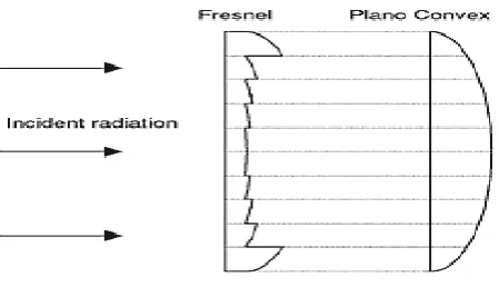
12.Lenses
Available Online at www.ijpret.com 610
PIR sensor and circuitry is fixed and costs a few dollars. The lens costs only a few cents and can chang the breadth, range, sensing pattern, very easily.
In the diagram up top, the lens is just a piece of plastic, but that means that the detection area is just two rectangles. Usually we'd like to have a detection area that is much larger. To do that, we use a simple lens (http://adafru.it/aKq) such as those found in a camera: they condense a large area (such as a landscape) into a small one (on film or a CCD sensor). For reasons that will be apparent soon, we would like to make the PIR lenses small and thin and moldable from cheap plastic, even though it may add distortion. For this reason the sensors are actually Fresnel lenses
Fig. No. 6 : The Fresnel lens condenses light, providing a larger range of IR to the sensor.
13.Software description
14.1 Tool
MATLAB (matrix laboratory) is a numerical computing environment and fourth-generation programming language. Developed by Math Works, MATLAB allows matrix manipulations, plotting of functions and data, implementation of algorithms, creation of user interfaces, and interfacing with programs written in other languages, including C, C++, Java, and Fortran.
Although MATLAB is intended primarily for numerical computing, an optional toolbox uses the MuPAD symbolic engine, allowing access to symbolic computing capabilities. An additional package, Simulink, adds graphical multi-domain simulation and Model-Based Design for dynamic and embedded systems.
Available Online at www.ijpret.com 611
14.2 Structures
MATLAB has structure data types. Since all variables in MATLAB are arrays, a more adequate name is "structure array", where each element of the array has the same field names. In addition, MATLAB supports dynamic field names (field look-ups by name, field manipulations, etc.). Unfortunately, MATLAB JIT does not support MATLAB structures; therefore just a simple bundling of various variables into a structure will come at a cost.
Function handles
MATLAB supports elements of lambda-calculus by introducing function handles, or function references, which are implemented either in .m files or anonymous/nested functions.
Classes
Although MATLAB has classes, the syntax and calling conventions are significantly different from other languages. MATLAB has value classes and reference classes, depending on whether the class has handle as a super-class (for reference classes) or not (for value classes). Method call behavior is different between value and reference classes.
14.3 GUI (Graphic user Interface)
MATLAB supports developing applications with graphical user interface features. It also
has tightly integrated graph-plotting features. The aim of this course is to develop initial skills for building Graphical User
Interfaces (GUIs) in MATLAB7. First we give a summary of MATLAB’s
graphics object hierarchy and review the syntax for accessing and manipulating
object properties. Then we discuss standard user interface components and
consider situations when descendants of axes can be used to design purpose built
graphical controls. Programming techniques are analyzed using moderately
simple conceptual examples and exercises. The structure of application
m-files generated by the MATLAB GUI development environment and some
techniques for inclusion of Java components and ActiveX controls into MATLAB
14.Programming MATLAB GUI
Available Online at www.ijpret.com 612
depend on the state of the GUI,so a standard mechanism is required which would allow each callback to routinely access Properties of objects. Data exchange must also be properly organized.A GUI writer must be aware of certain MATLAB language conventions. For example, if the callback property is specified as a string, then the callback expression is evaluated in DSTO–GD–0442 the base workspace, but if it is specified as a cell-array, then the variables additional to the callback object handle and the event data will be interpreted in the scop of the segment of the code where the callback property was originally set.
15.1 Background on MATLAB and the Image Processing Toolbox
Math and computation MATLAB is a high-performance language for technical computing. It integrates computation, visualization, and programming in an easy-to-use environment where problems and solutions are expressed in familiar mathematical notation. Typical uses include the following:
• Algorithm development • Data acquisition
• Modeling, simulation, and prototyping • Data analysis, exploration, and visualization • Scientific and engineering graphics
• Application development, including building graphical user interfaces
MATLAB is an interactive system whose basic data element is a matrix. This allows formulating solutions to many technical computing problems, especially those involving matrix representations, in a fraction of the time it would take to write a program in a scalar non-interactive language such as C.
The name MATLAB stands for Matrix Laboratory. MATLAB was written originally to provide easy access to matrix and linear algebra software that previously required writing FORTRAN programs to use. Today, MATLAB in corporate state of the art numerical computation software that is highly optimized for modern processors and memory architectures.
Available Online at www.ijpret.com 613
processing problems. Other toolboxes that sometimes are used to complement the Image Processing Toolbox are the Signal Processing, Neural Networks, Fuzzy Logic, and Wavelet Toolboxes.
The MATLAB & Simulink Student Version is a product that includes a full-featured version of MATLAB, the Image Processing Toolbox, and several other useful toolboxes. The Student Version can be purchased at significant discounts at university bookstores and at the MathWorks web site (www.mathworks.com). As we discuss in more detail in Chapter 2, images may be treated as matrices, thus making MATLAB software a natural choice for image processing applications.
15.Result
It is possible because of this to detect human motion and thus can be used to detect the presence of human. Once the presence of human is detected the relative relay can be operated and thus we can switch ON or OFF the electrical outputs.
16.CONCLUSIONS
Surveillance systems significantly contribute to situation control. Such systems transform video surveillance from a data acquisition tool to information and intelligence acquisition systems. Real-time video analysis provides surveillance systems with the ability to react to an activity in real time, thus acquiring relevant information at much higher resolution. The long-term operation of such systems provides the ability to analyze information in a spatial-temporal context. Because of motion sensors it is possible to detect the presence of human motion and can operate the related relay.
17.REFERENCES
1. Gareis, K. : Towards user orientation and social inclusion in the provision of e-learning
services.In e-learning Conference2005. (May 2005).
2. Hernandez, C., Casas, A Escarrbill, J ., Puig-Junoy, J., Farrero, E., Vilagut, G., Collvinent, B,
Rodriguez-Roisen, R., Roca, j.: Home Hospitalization of exacerbated chronic obstructive pulmonary disease patients. Volume 21.Eur Respiratory Soc (2003)
3. Trivedi, M., Huang, K., Mikic, I .: Dynamic context capture and distributed video arrays
Available Online at www.ijpret.com 614
4. Remagnino, P., Foresti, G., Ambient intelligence: A new multidisciplinary paradigm.
System Man and Cybernetics, Part A : Systems and Humans, IEEE Transactions on 35(1) (2005) 1{6
5. Sgroi, m.,Wolisz, A., Sangiovanni-Vincentelli, A., Rabaey, J.: A service-based universal
application interface for ad-hoc wireless sensor networks (draft). Whitepaper (November 2003)
6. _Alvro Araujo : Metodolog_ a para el desarrollo de aplicacionnesbasadas enservicios
sobreentornosinteligents.PhD thesis, Universidad Polit_ecnica de Madrid (2007)
7. Anafocus: Eye-RIS vision system evaluation kit. Hardware description.
8. Coleri, S., Puri, A., varaiya, P.: Power e_cient system for sensor networks. In : Computers
and Communication, 2003.(ISCC 2003). Proceedings. Eight IEEE International Symposium on.(2003) 837 {842 vol.2
9. Rabey, j.M.,Ammer,M.J.,da Silva,J.L., Patel,D., Roundy, S.: picoRadio supports ad-hoc