Examination of the demodulation effect of two-tone disturbances on
nonlinear elements
J. Nitsch1, N. Korovkin1, and E. Solovyeva2 1Otto-von-Guericke-University, Magdeburg, Germany 2State Electrotechnical University, St.-Petersburg, Russia
Abstract. The effect of two disturbing sources with close frequencies on a nonlinear circuit is investigated. It is shown that low-frequency oscillations occur in such a circuit. These low-frequency oscillations represent a significant threat to the electronic equipment, since standard filters do not sup-press low-frequency harmonics. On the basis of Picard’s iterations the synthesis of a protection system against low-frequency oscillations is performed.
1 Introduction
Nowadays, there is a marked trend for the increase in fre-quency and shifting of the amplitude maximum of noise fields into the high-frequency region (Keiser, 1979; Paul, 1992; Ianoz et al., 1997) . The shielding factor of non-ideal shields is reduced with increasing frequency (for example, the increase in the transfer impedance of cables with braided shields (Kaden, 1959; Lee and Baum, 1975; Demoulin, 1981; Gonschorek and Tiedemann, 2000; Demirchjan et al., 2003). Therefore, problems of protecting electronic devices, as a whole, become complicated with increasing frequency, and this trend will prevail in future.
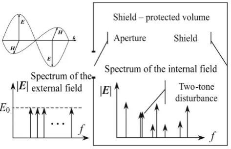
In the present paper the mechanism for the occurrence of low-frequency noise due to the demodulation of the ternal two-tone high-frequency electromagnetic field is ex-amined. The two-tone high-frequency electromagnetic field penetrates into the internal (protected) volume of the elec-tronic device and generates a low-frequency noise that propa-gates further into electronic circuits. This paper also demon-strates the universal way of suppressing this effect.
The low-frequency disturbances can produce a number of problems for the electronic equipment, among which we will note the following:
Correspondence to: N. Korovkin ([email protected])
– The frequencies in the(1−103)kHz range are consid-ered here as low-frequency noise, and can be close to operational frequencies of analog electronic devices. In this case, the low-frequency noise directly distorts a use-ful signal of the electronic device.
– The low-frequency noise can shift the operating points of transistor cascades of electronic circuits substantially and thereby changing their operating conditions.
– The low-frequency noise can be a source of dynamic instabilities in complex electronic systems.
It should be noted also that the low-frequency noise has weak attenuation in the circuits of the electronic equipment. Usually, internal filters for the suppression of low-frequency noise are not provided. Therefore, a low-frequency noise, if it occurs in an electronic system, can become “a source of problems” in those units which are located “electrically far” from the place of its origin.
The two-tone high-frequency electromagnetic field can be originated by different mechanisms. One of these is shown in Fig. 1. The technical system located in a shielded vol-ume is excited by an external electromagnetic field. Due to selective frequency properties of the cavity (Tkachenko and Vodopianov, 1998; Krauthaeuser et al., 2002; Tkachenko et al., 1999; Krauthaeuser et al., 2002) a two-tone signal may be produced.
52 J. Nitsch et al.: Demodulation effect of two-tone disturbances on nonlinear elements
Fig. 1. Two-tone signal due to the excitation of a cavity.
2 The action of two-tone high-frequency excitation on a nonlinear system
We examine the origin of a low-frequency disturbance which might become a typical EMC problem. The considered system (Fig. 2) contains: the loadR=50 kOhm which mod-els the input resistance of some electronic device (1 in Fig. 2), the source of the two-tone high-frequency disturbance:
e1(t )=600 [cos(ω1t )+cos(ω2t )] V, ω1=15·2π·106s−1,
ω2=16·2π·106s−1 (2 in Fig. 2), the simplest (L=10 mH) low-pass filter (3 in Fig. 2), and a nonlinear load (4 in Fig. 2)
unl=2768·i−4932·i2+3033·i3whereiis measured in mA.
In order to obtain the correct unit for the voltage u (nl), the necessary units have to be thought to be associated with the numerical numbers.
To calculate the steady state solution of the electrical cir-cuit of Fig. 2 we apply Picard’s iterations (Leon and Shaefer, 1977; Danilov, 1987; Rugh, 1981). After three iterations we getuR(t ), including harmonics of the frequencies(ω2−ω1),
ω1, andω2(the rest of the harmonics are small, so they are not listed), as follows:
uR(t )= [6.094+6.49 sin((ω2−ω1)t )+
+14.5 sin(ω1t+0.962)+14.0 sin(ω2t+0.978)]V. (1) The amplitude spectrum ofuR(t )is shown in Fig. 2. As is
obvious from Fig. 2 substantial low-frequency components are formed due to the nonlinearRL-circuit. It turns out that the amplitudes of the low-frequency oscillations are approxi-mately two times less than those of the high-frequency oscil-lations. The resistorRand the nonlinear element model cer-tain appropriate resistances of the electronic circuit. In prac-tice a large number of different real electronic circuits may be connected to the nodesα−α0andβ−β0. The low-frequency oscillations resulting from the examined demodulation phe-nomenon may propagate along these terminated circuits, en-countering no barriers. This is due to the fact that, usually, internal low-frequency filters are not installed. Therefore, as mentioned in the Introduction, the low frequency oscillations represent a special threat to electronic equipment.
Fig. 2. The action of two-tone high-frequency excitation on a non-linear system.
The more detailed consideration of the filter (unit 3 in Fig. 2) does not alter (neither qualitatively nor quantita-tively) the nature of the demodulation phenomenon. To show this we replace the filter in the circuit of Fig. 2 by the filter which is presented in Fig. 3. New circuit param-eters are: e(t )=1500 [cos(ω1t )+cos(ω2t )] V, the resistor
Rs=50 kOhm is connected in series with the nonlinear load
like before. The frequency dependence of the damping factor
αof theLC-low-pass filter is also presented in Fig. 3. For this calculation we assume the filter to be loaded with the linear term of the nonlinear resistor.
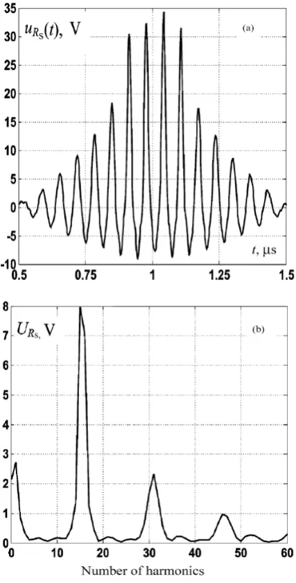
The plot of the voltage of the resistorRs=50 kOhm (for
one period) and the corresponding amplitude spectrum are shown in Fig. 4. We observe that substantial low-frequency components are also formed in the nonlinear circuit which contains theLC-filter. The amplitude of the low-frequency oscillation is approximately two times less than that of the high-frequency oscillations.
We draw some interim conclusions:
Fig. 3. Frequency dependence of the damping factor a of the
LC-low-pass filter.
– The low-frequency noise occurring in certain nonlin-ear circuits can further propagate along electric circuits of the protected device, because special means which limit this propagation are not provided, and its own at-tenuation is weak (due to the low frequency). Thus, it is expedient and necessary to provide protective means against low-frequency noise.
– At the presence of nonlinear elements in a protected device (that always can be assumed for electronic de-vices) and an assumed two-tone excitation, several re-peatedly reflected noises are rather probable. Then there will,however, arise a problem, because the frequency of that low-frequency noise is actually unknown at the be-ginning of an EMC investigation. This is due to many aspects. It strongly depends on the individual features of the specific device, such as different cable-layouts, relative positions of apertures in shielded volumina, etc. – Standard means to suppress low-frequency noise prop-agation, for example filters, will probably be inapplica-ble in the examined situation, since the noise frequency is not determined. The installation of filters with ex-cessively wide stop bands can create problems for the transmission of useful signals. For mobile objects it is
Fig. 4. Output voltage (a) and the amplitude spectrum (b) of the nonlinear circuit containing theLC-filter.
also necessary to take into account the significant sizes and weights of passive low-frequency filters.
From the above conclusions it follows that special protec-tive means are required. In this paper we propose to use in particular synthesized compensators as input nonlinearities in electronic devices.
3 The compensation of nonlinearity
54 J. Nitsch et al.: Demodulation effect of two-tone disturbances on nonlinear elements
(a)
(b)
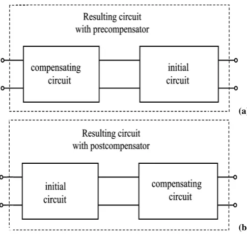
Fig. 5. Two cases of the connection of the compensator and the dis-torting circuit: with precompensator (a) and with postcompensator (b).
(distorting) circuit. Unique input-output relationship of the nonlinear circuit is described by the operator equation
y(t )=V1(p)x(t )+
N
X
k=2
Vk(p)x(t )=
=y1(t )+
N
X
k=2
yk(t ), ∀x(t )∈X,∀y(t )∈Y , (2)
whereV1(p)is the linear operator of the initial circuit, and
y1(t )the corresponding output signal. Vk(p)is the uniform
operator of powerk causing the presence of the nonlinear componentyk(t )of powerk in the output signal of the
cir-cuit.
The compensator synthesis problem lies in the construc-tion of a nonlinear operatorE(p)for the compensating cir-cuit which acts in equation (2) in the following way (Schet-zen, 1976):
ex(t )=V1(p)[E(p)x(t )] +
N
X
k=2
Vk(p)[E(p)x(t )] =
=Q(p)x(t ), (3)
or
ex(t )=E(p)[V1(p)x(t )] +E(p)[
N
X
k=2
Vk(p)x(t )] =
=Q(p)x(t ). (4)
Fig. 6. The precompensator and the distorting circuit.
Fig. 7. The amplitude spectrum of the output voltage.
Hereex(t )is the result of the compensation associated with the input signal of the initial circuit by a linear operator
Q(p). The series connection of the compensator is the usual way to connect it to an initial nonlinear circuit. Equation (3) is used to connect the compensator to the input of the initial circuit (Fig. 5). For the connection of the compensator to the output of the distorting circuit we use Eq. (4). In both cases we shall term the whole connection as the “resulting” one.
Fig. 8. The distorting circuit and postcompensator.
Volterra polynomials (Schetzen, 1976; Solovyeva, 1995). Using Picard’s series for the construction of the pre-compensator for the nonlinear electric circuit presented in Fig. 2, we obtain the resulting connection repre-sented in Fig. 6. The parameters of the linear part of the compensator are: C=10−5nF, Rd=354.91 kOhm,
R1=1000 kOhm and those of the nonlinear element are:
a22=−0.493·10−5, a32=0.303·10−8. Accordingly the char-acteristic of the nonlinear element of the compensating cir-cuit isi2=4.93·10−3u22−3.03·10
−6u3
2wherei2is measured in mA. The result of the compensation of the nonlinearity is shown in Fig. 7, which represents the amplitude spectrum of the output signal of the resulting circuit. Practically, the com-plete absence of lower harmonics in the amplitude spectrum of the output signal is obvious.
To construct the compensator for the circuit with theLC
filter, we use the approach based on the Volterra series. The compensator was connected behind the initial nonlinear de-vice. The resulting circuit is presented in Fig. 8, where
α2=0.1, α3=0.05, a1=0.0058, a2=−11.1111, a3=42.1053. The results of compensation are shown in Figs. 9–10. The relation between the nonlinear elementunl andiin the
postcompensator is given by:unl=2718·i−4932·i2+3033·i3
whereiis measured in mA,R2=50 kOhm. Figure 9 presents the output voltageuR2(t )of the initial circuit, and the output voltage of the composed circuit. Figure 10 depicts the pensation error (the difference between the result of com-pensation and the reaction of the linearRLC-circuit) and the amplitude spectrum of the output signal of the composed cir-cuit.
The analysis of Figs. 9–10 shows, that the synthesized compensator provides a high quality of noise suppression.
4 Conclusion
In this paper we have shown that a high frequency excitation of a system can be converted to a low frequency one, due to the interior features of the system itself. Nonlinearities are necessary for this high frequency- to low frequency- energy conversion. Beats or amplitude modulated signals with
Fig. 9. The voltage of the output of the initial circuit (a), and the voltage of the output signal of the circuit with postcompensator (b).
56 J. Nitsch et al.: Demodulation effect of two-tone disturbances on nonlinear elements
Fig. 10. The error of the compensation (a), and the amplitude spec-trum of the outtut voltage (b).
Acknowledgements. This work was supported by the state Saxony-Anhalt under the project number FKZ:3330A/0021T.
References
Keiser, B. E: Principles of Electromagnetic Compatibility, Artech House, Inc. Dedham, Mass., 1979.
Paul, C. R.: Introduction to Electromagnetic Compatibility, J. Wi-ley, N.Y., 1992.
Ianoz, M., Tesche, F. M., and Karlsson, T.: EMC analysis method and computational models, J. Wiley, N.Y., 1997.
Kaden, H.: Wirbelstr¨ome und Schirmung in der Nachrichtentech-nik, Berlin, Springer, 1959.
Lee, K. S. H. and Baum, C.: Application of Modal Analysis to Braided-Shielded Cables, IEEE Trans. EMC, 17, No. 3, 1975. Demoulin, B., Degauque, P.,and Cauterman, M.: Shielding
Effec-tiveness of Braids with High Optical Coverage, Int. Symp. on EMC, Z¨urich, 1981.
Gonschorek, K-H. Tiedemann, R.: Messung der komplexen Kabel-transferimpedanz bis 2 GHz, in: EMV 2000,D¨usseldorf, edited by Schwab, A., VDE Verlag, 2000.
Demirchjan, K., Neiman, L., Korovkin, N., and Chechurin, V.: The-oretical bases of the electrical engineering (in Russian), St. Pe-tersburg, Piter, 3, 2003.
Tkachenko, S. and Vodopianov, G.: Electromagnetic Field Cou-pling to an Electrically Small Scatterer in a Rectangular Cavity, Abstracts of the 11th Int. Conf. EUROEM’98, Tel Aviv, Israel, June 14–19, 1998, 41, 1998.
Krauthaeuser, H. G., Tkachenko, S., and Nitsch, J.: Starke An-hebung niederfrequenter Spektralanteile durch HF-Angerung von Hohlraumresonatoren, 10. Internationale Fachmesse und Kongress “Elektromagnetische Vertr¨aglichkeit”, 9–11. April 2002, 641, 2002.
Tkachenko, S., Vodopianov, G., and Martinov, L.: Electromagnetic field coupling to an electrically small antenna in a rectangular cavity, 13th Int. Z¨urich Symp.on EMC, Feb. 16–18, 1999, 379– 384, 1999.
Krauthaeuser, H. G., Tkachenko, S., and Nitsch, J.: The action of non-linear effects in a resonator, XXVIIth General Assembly of the Int. Union of Radio Science, Maastricht, the Netherlands 17– 24 Aug., 2002, N 2167, 2002.
Leon, B. I. and Shaefer, D. I.: Volterra series and Picard iteration for nonlinear circuit and system, IEEE Trans. CAS, 25, 6, 941–948, 1977.
Danilov, L. V.: Volterra-Picard series in the theory of nonlinear cir-cuits (in Russian), Moskow, Radio i Svyaz, 1987.
Rugh, W. J.: Nonlinear system theory, The Volterra/Wiener Ap-proach, Baltimore and London, The J. Hopkins Uni. Press, 1981. Schetzen, M.: Theory ofpth-order inverses of nonlinear systems,
IEEE Trans., CAS 1976, 23, 5., 285-289, 1976.