Contribution of the UPFC in Improving the Quality of
Electrical Power
DIB Djalel
Abstract – Unified Power Flow Controller (UPFC) is used to control the power flow in the transmission systems by controlling the impedance, voltage magnitude and phase angle. This controller offers advantages in terms of static and dynamic operation of the power system. It also brings in new challenges in power electronics and power system design. The basic structure of the UPFC consists of two voltage source inverter (VSI); where one converter is connected in parallel to the transmission line (STATCOM) while the other is in series with the transmission line (SSSC). We present in this paper a theoretical description of the UPFC system, its
modeling and a case study by simulation by
Matlab/Simulink. We investigate so, the effect of UPFC on the voltage of the related bus, it’s also considers the effect on the amount active and reactive power flowing through the transmission system. The aim of the paper is the modeling, the identification of the references and control of UPFC and studying its influence on the electrical network. Finally the simulation results have been presented to indicate the improvement in the performance of the UPFC to control voltage in power systems.
Keywords – FACTS, power transmission, three phase systems, transmission of electrical energy.
I.
I
NTRODUCTIONFlexible alternating-current transmission systems (FACTS) are defined by the IEEE as “ac transmission systems incorporating power electronics-based and other static controllers to enhance controllability and increase power transfer capability” [1]. Similarly, a FACTS controller is defined as “a power electronics-ased system or other static equipment that provides control of one or more ac transmission parameters”. In recent years, many different FACTS controllers have been proposed, performing a wide variety of functions. Review papers have surveyed them, the IEEE has listed definitions of them. The power flow over a transmission line depends mainly on three important parameters, namely voltage magnitude of the buses (V), impedance of the transmission line (Z) and phase angle between buses (θ). The FACTS devices control one or more of the parameters to improve system performance by using placement and coordination of multiple FACTS controllers in large-scale emerging power system networks to also show that the achieve significant improvements in operating parameters of the power systems such as small signal stability, transient stability, damping of power system oscillations, security of the power system, less active power loss, voltage profile, congestion management, quality of the power system, efficiency of power system operations, power transfer capability through the lines, dynamic performances of power systems, and the load ability of the power system network also increased. As FACTS devices are fabricated
using solid state controllers, their response is fast and accurate.
II.
G
ENERATION OFFACTS
C
ONTROLLERSIn general, FACTS controllers can be divided in following categories (Fig.1):
Series controllers such as Thyristor Controlled Series Capacitor (TCSC), Thyristor Controlled Phase Angle Regulators (TCPAR or TCPST), and Static Synchronous Series Compensator (SSSC)
Shunt controllers such as Staic Var Compensator (SVC), and Static Synchronous Compensator (STATCOM) Combined series-series controllers such as Interline Power Flow Controller (IPFC)
Combined series-shunt controllers such as Unified Power Flow Controller (UPFC) In this thesis we shall concentrate only on the TCSC, SVC, STATCOM, and UPFC devices.
Fig.1. Principals Dispositive of FACTS Systems
III.
U
NIFIEDP
OWERF
LOWC
ONTROLLER,
UPFC
is able to control, concurrently or selectively, the transmission line voltage, impedance, and angle or, alternatively, the real and reactive power flow in the line. The UPFC may also provide independently controllable shunt reactive compensation.
The UPFC consists of two voltage source converters; series and shunt converter, which are connected to each other with a common dc link. Series converter or Static Synchronous Series Compensator (SSSC) is used to add controlled voltage magnitude and phase angle in series with the line, while shunt converter or Static Synchronous Compensator (STATCOM) is used to provide reactive power to the ac system, beside that, it will provide the dc power required for both inverter. Each of the branches consists of a transformer and power electronic converter. These two voltage source converters shared a common dc capacitor.
Fig.2. Schematic of three phases connecting between Power network and UPFC
The energy storing capacity of this dc capacitor is generally small. Therefore, active power drawn by the shunt converter should be equal to the active power generated by the series converter. The reactive power in the shunt or series converter can be chosen independently, giving greater flexibility to the power flow control. The coupling transformer is used to connect the device to the system. Figure 2. Shows the schematic diagram of the three phases UPFC connected to the transmission line.
A.
Operating diagrams of the UPFC.
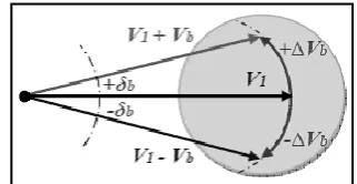
We can summarized the principals functions of the UPFC in the following diagrams:
Fig.3. A. A pure voltage regulator if the voltage Vb is inserted in phase with the voltage V2
Fig.3.b. Impedance controller (compensator series) if the additional voltage Vb is perpendicular to the line current ir
Fig.3. c. A regulator of the phase angle if the amplitude and phase of the voltage Vb injected are calculated so as to obtain the same module of the voltage before and after the
UPFC.
Fig .3. d. The UPFC is able to combine the different compensations of earlier and switch from one mode to
another perpendicular to the line current ir. Fig. 3. Principals functions of the UPFC (a),(b),(c) and (d)
B.
UPFC Modeling
To proceed to the modeling of the UPFC, we chose the structure of the following figure of a single phase connected in an electrical system Fig. 2 shows the detailed model of UPFC. Where, Lsh; Lsr and Rsh; Rsr represent leakage inductances of transformers and losses of inverters and transform- ers. The terms of Nsh and Nsr are the turn ratio of shunt and series coupling transformers. The series inverters act as SSSC. It injects voltage, Vser, in series with the transmission line. The KVL equations of series and shunt inverters are:
With applying this transformation to equations (1) and (2), the equations (6) and (7) can be obtained, respectively.
IV.
I
DENTIFICATION ANDC
ONTROLTheoretically, the UPFC device should be treated as a multivariable because each one of the two converters has two inputs and outputs ( Fig. 5). However, to facilitate the processing of the device, control of both converters will be done separately [3]. For each one, there is a method for identifying references and the control the inverter, among the methods used to determine the reference, we chose the method decoupled Watt-Var for each part.
Fig.5. Three phase UPFC connected in the electrical network used control and simulation
A.
Functional control of shunt inverter (STATCOM)
The shunt inverter is used for voltage regulation at the point of connection injecting an opportune reactive power flow into the line and to balance the real power flow exchanged between the series inverter and the transmission line.
The shunt inverter is operating in such a way to inject a controllable current Ic into the transmission line.
This current consist of two components with respect to the line voltage
The real or direct component id
Reactive or quadrature component iq
The direct component is automatically determined by the requirement to balance the real power of the series inverter. The quadrature component, instead, can be independently set to any desired reference level (inductive or capacitive) within the capability of the inverter, to absorb or generate respectively reactive power from the line. So, two control modes are possible:
VAR control mode: the reference input is an inductive or capacitive var request;
Automatic Voltage Control mode: the goal is to maintain the transmission line voltage at the connection point to a reference value.
B.
Functional control of series inverter (SSSC)
The series inverter can be used to control the real and reactive line power flow inserting an opportune voltage with controllable magnitude and phase in series with the transmission line.
The series inverter injects a voltage, Vse which is controllable in amplitude and phase angle in series with the transmission line. This series voltage can be determined in different ways:
Direct Voltage Injection mode: The reference inputs are directly the magnitude and phase angle of the series voltage;
Phase Angle Shifter Emulation mode: The reference input is phase displacement between the sending end voltage and the receiving end voltage;
Line impedance emulation mode: he reference input is an impedance value to insert in series with the line impedance;
Automatic Power flow Control mode: The reference inputs are values of P and Q to maintain on the transmission line despite system changes.
Fig.6. Overall pattern, of control of the UPFC shunt part
Fig.7. Overall pattern of control of the UPFC series part
The comparison between (ir-d, ir-q) and the reference current (ir-d*, ir-q*) shows the differences that pass by regulators, as indicated in fig. 7. The regulator outputs (X1and X2) give the reference voltage components of the PWM in the dq reference. The inverse of PARK transformation, allow obtaining the PWM references to control the series part. Same thing about the shunt part [6].
The identification of reference current by instantaneous power method is the same in the two UPFC part. The Fig.8, shows the Overall pattern of instantaneous power method for UPFC.
Fig.8. Overall pattern of instantaneous power method
V.
S
IMULATIONThe simulation we performed with the software MATLAB / SIMULINK, first assume that the electric network gets a disruption (short-circuit) (Fig 9) and second, implement the UPFC with the network and see its influence Fig(19).
A.
Short-circuit in the network
Fig.10. Voltage magnitude at the source voltage
Fig.11. Current magnitude at the source voltage
Fig.12. Real power at the source voltage
Fig.13. Voltage magnitude at the resistive load
Fig.14. Current magnitude at the resistive load
Fig.16. Voltage magnitude at the RL load
Fig.17. Current magnitude at the RL load
B.
Implementation of UPFC in the Electrical network
Fig.19. Electrical network with short-circuit with UPFC system
Fig.20. Voltage magnitude at the resistive load
Fig.21. Current magnitude at the resistive load
Fig.22. Real power at the resistive load
Fig.23. Current magnitude at the RL load
Fig.25. Real power at the RL load
VI.
R
ESULTS ANDD
ISCUSSIONIn the normal currents and voltage source and load are stable and follow their powers and that reference is clearly observable in the figures (6).
The case of active power variation at the level of loads: the objective of this test is to see the behavior of the UPFC active power to enslave.
In case the network without UPFC, power is increased when requested by the load curve we can see from the figure (7) and figure (8) that the power delivered to the load is insufficient. For the implementation of UPFC, based on figures (9) and (10). we note that the active powers follow their references, this validates the proper functioning of the regulators of the part series (SSSC) of the UPFC. In figure (11-22) is clearly seem the influence of the party shunt (STATCOM) on the regulation of the currents.
If a short circuit at the source: in the interval [0s, 0.1s] a single-phase short circuit causes a voltage drop in phase aggressive and huge increase in phase current and make a disturbance and imbalance of voltage, current and power at the level of loads, from a figures (12) we see the influence of short-circuit power grids without UPFC.
When a power system with UPFC caused by a short phase, the voltage drop of the phase and decreases due to regulation by shunt, the phase voltage at the connection point is compensated and the compensation is illustrated in figures (13-14-20). Indeed, the party shunt injected (or consume) reactive power so that the line voltage remains constant.
VII.
C
ONCLUSIONIn this study, the matlab/simulink is used to simulate the model of UPFC connected to a three phase-three wire transmission system. This paper presents control and performance of UPFC intended for installation on a transmission line. A control system is simulated with shunt inverter in ac and dc voltage control mode and series inverter in open loop phase angle control mode.
Simulation results show the effectiveness of UPFC in controlling real and reactive power through the line. The compensation of an electrical system by using UPFC -facts device has been studied in this research work. Two important coordination problems have been addressed in this paper related to UPFC control.
One, the problem of real power coordination between the series and the shunt converter control system. Second, the problem of excessive UPFC bus voltage excursions during reactive power transfers requiring reactive power coordination. The simulation results, obtained by matlab show the efficiency of UPFC, in controlling line both active and reactive power flow.
The facts systems stem from a concept that tends to expand its field of intervention, it seems a priority to continue the research on control strategies and modes of transmission of electrical energy by the device and have so a UPFC better power quality.
R
EFERENCES[1] M. Noroozian, L. Angquist, M. Ghandhari, and G. Anderson, “Use of UPFC for optimal power flow control,” IEEE Trans. on Power Delivery, For a book citation:
[2] Zhang. Rehtanz. Pal „‟Flexible AC Transmission Systems: Modelling and Control„, Springer-Verlag Berlin Heidelberg 2006.
[3] L-Gyugyi, „‟Unified power-flow concept for flexible ac transmission systems‟‟, IEEE Proceedings-C, Vol. 139, No.4, July 1992, pp. 323-33 10.
[4] Le DU A., “Pour un réseau électrique plus performant: l e projet FACTS” RGE n°6/92, juin 1992, pp.105-117. [5] Belcheheb K., Saadate S., “utilization of the UPFC for
optimal exploitation of costly centrals in the electrical systems”, PEMC‟98, Prague Czech Republic, September 98.
[6] L. Gyugyi, “Unified power flow control concept for flexible AC transmission systems generation,” in proc. Transmission distribution conf. vol 139, July 2003, pp.323-331.
[7] Douglas J., Heydt G.T., “ Power flow control and power flow studies for systems with FACTS devices, in IEEE transactions on power systems,vol.13,n°1,February 1998, pp. 60-65.
[8] J. F. Keri, “Unified Power Flow Controller (UPFC): Modeling and analysis.” IEEE. Trans. Power Delivery, vol. 14. pp.648-654, apr. 1990.
[9] L. Gyugi, \A Uni¯ed Power Flow Control Concept for Flexible AC Transmission Systems," IEE Proceedings, Vol.139, No.4, pp. 323-331, July 1992.
[10] L. Gyugyi, C.D. Schauder, et al, \The Unifed Power Flow Controller: A New Approach to Power Transmission Control," IEEE Transactions on Power Delivery, Vol. 10, No. 2, pp.1085-1093, April 1995.
[11] H. Fujita, Y. Watanabe, H. Akagi, \Control and Analysis of a Unifed Power Flow Controller," IEEE Transactions on Power Electronics, Vol.14, No.6, pp. 1021-1027, November 1999.
[12] S.H. Hosseini, A. Ajami, \Dynamic Compensation of Power Systems Using a Multilevel Static Synchronous Series Compensator," the 8th International Iranian Conference on Electrical Engineering, May 2000. [13] S. Round, Q. Yu, et al, \Performance of a Unifed Power
Flow Controller Using a d-q Control System," AC and DC Transmission Conference, April 1996.