Copyright © 2015 CTTS.IN, All right reserved
Effect of Reaction Plate on Performance of Single-Side Linear
Induction Motor in Different Speeds and Frequencies with
Finite Element Method
O. Maktabdar
MSC Student, University of Birjand, Birjand, Iran, [email protected]
M. Shamsinezhad
Department of Electrical and Computer Engineering, University of Birjand, Birjand, Iran, [email protected]
H. Eliasi
Department of Electrical and Computer Engineering, University of Birjand, Birjand, Iran, [email protected]
Abstract – Single-sided linear induction motor (SLIM) has many advantages, such as simple structure, easy maintenance, less environmental pollution and direct drive without the translation of mechanisms etc. This paper deals with the analysis of linear induction motor behavior which includes flux distribution, surface current density & magnetic vector potential etc. Using finite element method, we evaluate the electromagnetic behavior of the SLIM by material of reaction plate changing to get the comparative performance analysis with different materials used. The simulation work has been carried out using Ansys’s Maxwell v.15 software Package.
Keyword – Linear induction motor, FEM, reaction plate, speed and frequency changes, horizontal force , loss.
1. I
NTRODUCTIONLinear motor is an electric motor that has come rather than rotating torque and rotary move, linear force production, causative factor of linear force and the electromagnetic field. One type of linear motors is single-side linear induction motor. This has many advantages such as simple structure, low maintenance, no need for mechanical connectors for power transmission and operation cost is low. However, the interest rate, low power factor, the end effects and side effects are major weaknesses of the linear motors. Nowadays the designers with the discovery of development to modification and optimization Components of motor performance characteristics have been considered.
Linear induction motor has been applied in urban transportation system widely, mainly because of its low cost construction of lines and stations using small cross-section and improved sharpness and steepness gradient of electromagnetic field curves. However, LIMs have an extremely obvious disadvantage with end effect and large air gap, which turns out to be very low power factor and efficiency. Many researches have been done concentrated in reducing the influence of end effect and improving LIM’s efficiency.
In this paper, Using finite element method, we evaluate the electromagnetic behavior of the SLIM by material of reaction plate changing to get the comparative performance analysis with different materials used.
2. T
HEE
QUIVALENT CIRCUIT OFSLIM
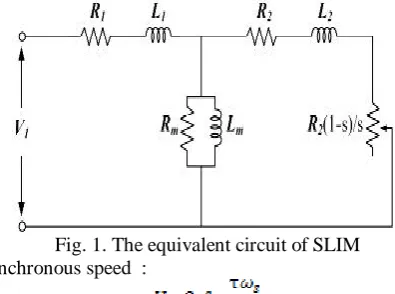
Because SLIM structure is similar RIM, with this difference that SLIM is flat, to obtain the Equivalent circuit of SLIM, the equations of rotation induction motor (RIM) is used. The stator and rotor of RIM respectively called primary and secondary coils in SLIM. Irrespective of the end effect, the equivalent circuit for single phase motors and some of the basic relationships as follows:
Fig. 1. The equivalent circuit of SLIM Synchronous speed :
Rotor speed V is less than the synchronous speed. Slip as follows:
3. F
INITEE
LEMENTA
NALYSISTo solve the Maxwell’s equations in linear induction motor, it can use several ways; the most famous is the finite element method. In this method, the equations are separated by the finite element method. Finally, differential equations are solved by the Galerkin method. Finite element analysis is useful tools for the analysis of electromagnetic fields in electric machines.
Finite element method is used for solving electro-magnetic equations involving Maxwell's equations of the electromagnetic. The equations are as follows:
(1) Eq (1) is magnetic Gauss's law where "B" is the magnetic flux density.
(2)
Eq (2) which Faraday's law where "E" is the electric field intensity.
(3) Eq (3) is the Gauss law. Where "ρ" electric charge density and "D" is the density of the electrical polarity.
(4) Eq (4) Ampere's law is generalized. In this equation, "J" and "H" respectively is electric charge density and magnetic field intensity.
Also Ohm's law can be expressed as follows:
(5)
4. S
TRUCTURED
ESIGNO
FSLIM
Three-dimensional Maxwell software was used to simulate and study the characteristics of the electromagnetic model of SLIM with finite element analysis. This software can solve electromagnetic equations, mechanical and dynamic boundary conditions. Structure of a single-sided linear induction motor consists of two basic parts. Part one includes the winding and called "primary". It is known that the magnetic field in the air gap is created and the other part called "secondary" that consequently, due to the reaction between the secondary flow and magnetic field in the air gap in which motor thrust is formed. The boundary conditions and excitation parameters of SLIM models, has been fixed. The finite element analysis needs large computation and therefore requires a long time to achieve the desired results. Therefore, usually for simulation, two-dimensional designing with “mm” as dimensions of the unit is selected.
5. FEM-S
IMULATIONW
ITHMAXWELL
Maxwell software is a useful tool for the analysis of electromagnetic fields in objects such as motors, generators, transformers, coils and magnetic devices. This software is based on the finite element method. In this method, components of the model are split up in small elements that are called mesh. In addition for solving equations, it needs to define boundary conditions
in boundary between different components of the model. Boundary conditions are necessary conditions for the exact solution of analytical equations.
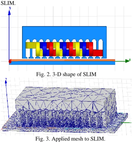
The motor is designed 3-D. A symmetrical three-phase model with a 120 degree phase difference for the primary windings is used. Type of primary windings is a fractional step and motor is four-pole. Figure 2 shows the 3-D shape of SLIM and Figure 3 shows applied mesh to SLIM.
Fig. 2. 3-D shape of SLIM
Fig. 3. Applied mesh to SLIM.
Table. 1 shows the parameters of designed SLIM in Maxwell software.
Table (1) parameters of designed SLIM in Maxwell
Parameter Values
Phase Voltage (V) 220
Air gap (mm) 2
Primary Length (mm) 200
Secondary Length (mm) 1200
Pole Step(mm) 45
Number of Poles 4
Number of Slots 12
Turn of Coil 110
R ( ) 35
L (H) 0.1
6. S
IMULATIONR
ESULTSIn this section, effects of four parameters changes on behavior of SLIM are studied and analyzed. These parameters are material of RP, thickness of RP, motor speed and motor frequency.
6.1. Change of Material of RP
Copyright © 2015 CTTS.IN, All right reserved compare the output of the flux density, force of vertical
and horizontal, losses and efficiency.
Table (2) effect of changing in materials of RP on SLIM performance
Steel Iron Aluminum Copper
Output items
3.3 3.1 30
36
Force_ x (N)
21 18 8
5.5
Force_ y (N)
15.2 12
39 50.7
Efficiency
( )%
22.6 4 24 12.2
10.44
Loss RP (W)
10.8 10.1 31.1
36.8
Mag_B (mT)
Table 2, shows the effect of changing in materials of RP on performance of SLIM. SLIM with "copper" as RP have best efficiency and maximum horizontal force and minimum losses. Model includes "steel" as RP has the worst results. The subsequent comparison of the models we use copper as the default.
6.2. Change of Thickness RP
With results has been obtained in previous section, performance of SLIM with RP of copper in four thicknesses of 3, 2, 1 and 0.5 millimeters simulated. Thickness more than three millimeters is not used, because of high cost.
Results of the four simulated models are shown in Table 3. The model is designed with a thickness of 3 mm copper has the best performance and maximum horizontal force and minimum losses, in comparison with other cases.
Table (3) effect of changing in thickness of RP (Copper) on SLIM performance
3 mm 0.5 mm
Output items
40.5 8.3
Force_ x (N)
5.2 5.6
Force_ y (N)
% 60.7 %38.6
Efficiency %
6.3 15.7
Loss RP (W)
42.1 19.3
Mag_B (mT)
In the following, to analyze the changes of speed and frequency, SLIM designed with the RP material with "copper 3mm" is used as the default.
6.3. Speed Changes
In this section performance of SLIM at different speeds is simulated and analyzed. Efficiency, force of horizontal and losses are compared in difference speed. SLIM is simulated in speed of 0 to 5 , with 0.5 steps.
Figure 5 shows that SLIM has a maximum power output at a speed of 2.5 meters per second.
Fig. 5. Power of SLIM in different speed
Figure 6, shows the horizontal force changes at different speed of SLIM. The horizontal force has maximum domain of oscillation in speed of 2.5 . Horizontal force is 38 N at steady state.
Fig. 6. Horizontal force of SLIM at different speed
Figure 7 shows the Changes of electromagnetic field loss of SLIM at different speeds. In speed of 3 , electromagnetic field has lowest loss. Loss of field is increased with increasing speed.
Fig. 7. electromagnetic field loss of SLIM at different speeds
Graphical plot of flux density distribution is shown in figure 8. The middle slots have flux density more than other parts of the SLIM.
6.4. Frequency Changes
Finally, effect of frequency on efficiency, horizontal force and losses at different frequencies is studied. In this section, SLIM at frequencies of 45 to 65 Hz is simulated. Figure 9 shows the horizontal force in different frequency. As shown in figure 9, horizontal force decreases with increasing frequency. Also Figure 10 shows the output power versus time at different frequencies. With increasing frequency, power output is reduced. At the steady state, maximum power output is in frequency of 45 Hz and minimum output power in frequency of 65 Hz.
Fig. 9. horizontal force in different frequency
Fig. 10. Output power in different frequency
Also losses-frequency diagram is shown in the Figure 11. It can be seen that losses decreases with increasing frequency.
Fig. 11. Losses-Frequency diagram
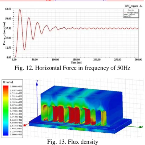
Figure 12 shows the horizontal force in frequency of 50Hz and in the Figure 13 a 3-D graphical plot of SLIM flux density distribution is shown. The steady state of horizontal force is 37.5 N. Flux density is 0.2 T in steady state at the middle Slots.
Fig. 12. Horizontal Force in frequency of 50Hz
Fig. 13. Flux density
7. C
ONCLUSIONIn this paper, equivalent circuit of the single-sided linear induction motor and fundamental equations are introduced. Then finite element method is used to study numerical analysis of electromagnetic fields of SLIM. Ansys Maxwell software is used For simulation and analysis of electromagnetic Fields in SLIM. Using finite element method, SLIM is simulated. Using a variety of conventional conductive materials in the RP, performance of SLIM was studied with changing in material and thickness of the RP. According to resualts, the optimal model calculated and it was analyzed in different speed and frequencies. The results are used to obtain the optimal speed and frequency for SLIM.
R
EFERENCE[1] T. Yamaguchi, Y. Kawase, M. Yoshida, Y. Saito, and Y. Ohdachi, “3-D finite element analysis of a linear induction motor,” IEEE Trans. Magn., Vol. 37, NO. 5, pp. 3668–3671, 2001.
[2] Dong. Li, Weili. Li, Jin. Fang and Xiaochen. Zhang, “Investigation of a Low-Speed Single-Side HTS Linear Induction Motor With Different Primary Structures Used for Linear Metro,” IEEE Trans. Applied Superconductivity, Vol. 24, NO. 2, pp. 256-265, 2014.
[3] Meng. Li, Zhongping. Yang, Fei. Lin and Hu. Sun, “Characteristics of Linear Induction Motor Considering Material of Reaction Plate Change,” IEEE Trans. Joural of Computers, Vol. 8, NO. 1, pp. 102-107, 2013.
Copyright © 2015 CTTS.IN, All right reserved [5] A. Zare Bazghaleh, M. R. Naghashan, and M. R.
Meshkatoddini, “Optimum design of single-sided linear induction motors for improved motor performance,” IEEE Trans. Magn., Vol. 46, NO. 11, pp. 3939–3947, 2010.
[6] A. H. Selcuk and H. Kurum, “Investigation of end effects in linear induction motors by using the finite-element method,” IEEE Trans. Magn., Vol. 44, No. 7, pp. 1791–1795, 2008.
[7] A. H. Isfahani, B. M. Ebrahimi, and H. Lesani, “Design optimization of a low-speed single-sided linear induction motor for improved efficiency and power factor,” IEEE Trans. Magn., Vol. 44, No. 2, pp. 266–272, 2008.
[8] M. Mirsalim, A. Doroudi, and J. S. Moghani, “Obtaining the operating characteristics of linear induction motors: A new approach,” IEEE Trans. Magn., Vol. 38, NO. 2, pp. 1365–1370, 2002. [9] J. Han and Y. Li, “Dynamic Characteristics Study
of Single-Sided Linear Induction Motor with Finite Element Method,” IEEE Conf. Advanced Intelligent Mechatronics, 2008.