Please cite this article as: E. Poursaeidi, M. R. Mohammadi Arhani, Reverse Engineering for Designing the Coupling of a 32 MW Rotor-generator by Shrink Fitting Method, International Journal of Engineering (IJE), TRANSACTIONS C: Aspects Vol. 28, No. 9, (September 2015) 1375-1382
International Journal of Engineering
J o u r n a l H o m e p a g e : w w w . i j e . i rReverse Engineering for Designing the Coupling of a 32 MW Rotor-generator by
Shrink Fitting Method
E. Poursaeidi*, M. R. Mohammadi Arhani
Department of Mechanical Engineering, University of Zanjan, Zanjan, Iran
P A P E R I N F O
Paper history:
Received 22 September 2014
Accepted in revised form 03 September 2015
Keywords:
Reverse Engineering Rotor-generator Coupling, Shrink Fitting Stress Analysis Finite Element
A B S T R A C T
This study presents a designing process for refurbishing of a 32 MW rotor-generator damaged coupling. The reason of rotor damage was being hit by the quivers of an explosion. The original coupling was union with the rotor formed after a machining process on a mono block forged rotor. In some areas imposed damages caused the breaking off and detachment of some parts in the coupling flange. Because of this accident, the coupling region was removed by machining completely and another coupling was made and mounted on the rotor-generator shaft by shrink fitting. Reverse engineering method was used with comparing a 145 MW rotor-generator. At first, all of the mechanical loadings on the coupling were assessed. The calculations include analytical method using ANSI standard and simulation of ANSYS software. The results showed that in spite of geometrical restrictions, it is possible to install a distinct coupling by shrink fitting on the rotor generator shaft.
doi: 10.5829/idosi.ije.2015.28.09c.16
NOMENCLATURE
P Mechanical pressure on the shrunk fit surfaces (Pa) Dpin Diameter of pins (m)
E Modulus of elasticity (Pa) Lpin Length of pins (m)
Ris Internal radius of shaft (m) t1 Initial temperature of coupling, during assembly on the shaft (◦C)
Ric Internal radius of coupling (m) t2 Final temperature of coupling, during assembly on the shaft (◦C)
Roc External radius of coupling (m) Greek Symbols
Kτ Stress concentration factor δ Geometrical interference between coupling and shaft (m)
Pmech Generator mechanical input power (Watt) στs Tangential stress on the contacted surfaces of shaft (MPa)
TG Generator consuming torque (N.m) στc Tangential stress on the contacted surfaces of coupling (MPa)
Tall Allowed torque (N.m) ωG Rotor angular velocity (rad/sec)
f Friction force α Coefficient of thermal expansion
D Diameter (m) Subscripts
Lc Length of contacted surface in shrunk fit (m) C Coupling
npin Number of pins S Shaft
1. INTRODUCTION1
Shaft is one of the most important mechanical transmission elements which needs to be coupled
1*Corresponding Author’s Email: [email protected],
[email protected] (E. Poursaeidi)
properly by the use of shaft couplings. A coupling is mainly to connect two shafts semi permanently [1]. Shrink fitting is one of the common methods in industry which engineers use it from long time ago. In fact, one of very strong and precise methods in manufacturing of non-permanent connections is this one, whereas, in the large rotors, in which it is not possible to make a rotor
in one piece, the couplings on the both sides of the rotor will be installed by mentioned methods. Another application is in installing axial compressor discs on the rotor shaft. The discs expanded by an induction heating system are installed respectively on the main shaft that is rather cold, and after becoming isotherm, a very strong fitting will be made. The experience shows that, in some cases this kind of junction, specifically in compressor discs, is very susceptible to sudden fracture [2]. Fretting fatigue is caused by micro-slip of the contact surfaces and formation of highly stressed zones near the contact surfaces [3].
Another application is in manufacturing of high technology rotors which have underwear parts. As an example, in manufacturing of screw type compressor rotors where it has high accuracy and complexity, for installing the driving gear that is an underwear element, the shrink fitting method will be used 1.2The advantages of using this method are: there is no need to use key joint for making the gear to move less on the rotor shaft and subsequently the rotor balancing after changing of the gear is not required. In any case, this kind of connection in the mentioned applications is too strong in which in spite of heavy loadings, two connected elements usually have no slip on each other. For example, in the case of rotor-generator coupling, in fact, the role of this element is power transmission from the turbine to the generator and with due attention to the rotor-generator dipole field in each revolution, it encounters with an induced resistant torque, influenced by stator poles and will be released by passing through the magnetic field lines [4]. This phenomenon, when the rotor-generator revolves with high speed, iterates several times per second depending on the numbers of rotor and stator poles and revolution speed.
In these conditions all of the power transmission paths will be influenced by mechanical resistance load (frequency type), and it can be seen in the contact surfaces between the coupling and rotor-generator shaft. They are connected to each other by a large friction force influenced by a shrink pressure. In rotating parts, the shrink pressure will be weakened in the elastic range due to the creature of centrifugal forces on the shrink fitted part. So, applying this method has dimensional restrictions for the shaft and shrink fitted part for kinds of connections are calculated and presented in the ANSI B 4.2 standard. Nevertheless in big parts like the axial compressor discs that have quite large outer diameter, the calculation of centrifugal force causing the decrease of shrink fitting force on the shaft, is necessary [5]. But in the couplings, due to less mass and diameter, the centrifugal force has negligible influence on the shrink fitting pressure decrease. In spite of the fact, the more the outer diameter of shrink fitted part is, by creating
1. Atlascopco stationery air compressor service manual www.atlascopco.com.
3). A separate coupling was made and created on the shaft by shrink fitting method and installed at the end of the rotor-generator. In this way, reverse engineering method was used by comparing with a 145 MW rotor-generator in which its coupling was distinct and was installed by shrink fitting method. All of the mechanical loadings on the coupling were calculated and assessed. Calculations included analytical method using ANSI standard initially and in the last step, for verifying the calculation correctness, simulation by finite element method using the ANSYS software was done. The results of calculations and analysis showed that in spite of some geometrical restrictions, installation design of a separate coupling by shrink fitting method on a 32 MW rotor-generator is possible and finally the following coupling was manufactured and installed on the rotor (Figure 4)3.
Figure 1. Damaged coupling due to an explosion event
Figure 2. Penetration test result after refurbishing by welding and machining procedure
Figure 3. The rotor end after removing the main forged coupling by machining procedure
Figure 4. Installing a new shrink fit coupling on the rotor end
3 Iran Powerplant Repair Co., "Feasibility study of making a damaged coupling of 32MW rotor generator", Winter, 2008
2. RESEARCH METHOD
In the first step, reverse engineering method was used for general form of coupling and arrangement of cylindrical key pins inspired from the design of a 145 MW rotor-generator. Using ANSI B 4.2 standard, the value of allowed shrink based on ultimate diameter of the shaft -204mm- at the end of the 32 MW rotor-generator was selected. With due attention to the maximum allowed diameter, because of dimensional restrictions in the coupling flange of 32 MW rotor-generator and required space for its bolting, the coupling boss diameter is determined about 280 mm and the value of tangentional stress using the theory of thick-walled cylinders, is calculated without consideration of key ways and the bolting bores on the flange. In the subsequent step, values of tangentional stress were modified, using stress concentration factors for cylindrical key ways and assuming the existence of tensile stress on the inner surface of the coupling. So, maximum effective tensile stresses were resulted. These values of stress were compared with the minimum values of consumed material yield strength, so the minimum factor of safety was calculated in the ambient temperature. Calculations showed that the coupling which is in the process of design has a relatively lower safety factor compared with the base coupling of the 145 MW rotor-generator. Also it can be seen in the calculations that there was a difference about 10 MPa between the values of tangentional stresses on the inner surface of the couplings. This one was calculated about 173 MPa for the design coupling, whereas this value was about 163.4 MPa for the original coupling used in the 145 MW rotor.
Notice that the comparison between tangentional stresses is important because only this stress makes rupture in the inner side of thick-walled cylinders; and in no pressurized condition its value is zero. But after shrink fitting procedure, the stress increases depending on the value of two cylindrical parts interference, due to creation of elastic strain. This generated stress must not exceed from the material yield limit, considering a safety factor. Figure 5 presents the schematic view of stress gradients for a part of two thick walled cylinders due to a geometric interference. As it is shown, the tangential stress on the outer cylinder is tensile with positive sign and for the inner cylinder is compressive with negative sign.
the shaft and coupling are used for more safety consideration.
The recommended factor of safety was considered according to API 671 (1998). With these factors of safety one can compare couplings for a particular application. Table 1 shows the recommended minimum design factors of safety for various rating factor basis of safety. Finally, the values in Table 1 are recommended as a guide and do not reflect how good a job was done in determining and combining the stresses used to obtain them.
3. STRESS CALCULATIONS
As it was pointed before, the most important effective load on the coupling cylinder is the tensile stress generated by shrink fitting force and the other loads are in lower levels of validity. Figure 6 shows the base of calculation in stress analysis of thick-walled cylinders to use shrink fitting process for the coupling on the shaft.
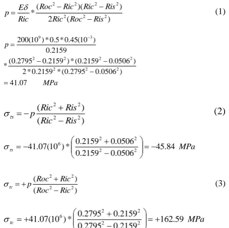
In the first step, it is considered to calculate the values of tangentional stresses on the inner surface of the 145 MW rotor-generator coupling, using sizes and dimensions in Figures 7 and 8; Equations (1) to (3) are used [8].
TABLE 1. Minimum factors of safety [9]
Coupling capacity Design factor Basis of factor of safety Max. continuous
Rating
1.25-1.35
Min* Endurance
Peak rating 1.15 Min Yield
Max momentary
Rating 1.0 Min Yield
Figure 5. Schematic view of stress distribution for two shrunk fit thick walled cylinder
Figure 6. Dimensional specifications for two shrunk fit cylinders ) ( 2 ) )( (
* 2 2 2
2 2 2 2 Ris Roc Ric Ris Ric Ric Roc Ric E p
(1)
MPa p 07 . 41 ) 0506 . 0 2795 . 0 ( * 2159 . 0 * 2 ) 0506 . 0 2159 . 0 ( * ) 2159 . 0 2795 . 0 ( * 2159 . 0 ) 10 ( 45 . 0 * 5 . 0 * ) 10 ( 200 2 2 2 2 2 2 2 3 9 ) ( ) ( 2 2 2 2 Ris Ric Ris Ric p s (2) MPa
s 45.84
0506 . 0 2159 . 0 0506 . 0 2159 . 0 * ) 10 ( 07 .
41 2 2
2 2
6
) ( ) ( 2 2 2 2 Ric Roc Ric Roc p c (3) MPa
c 162.59
2159 . 0 2795 . 0 2159 . 0 2795 . 0 * ) 10 ( 07 .
41 2 2
2 2
6
In the second step, the value of tensile stress in the pinholes, determining the stress concentration factor Kτ, is calculated. For this purpose, with due attention to Figure 7, the value of stress στc, calculated in the
followed equations, is only correct for the last part of coupling boss, which is like a cylinder without considering geometrical discontinuity. Existence of pin holes causes stress concentration Kτ in the flange side part and the middle part of the coupling, where its maximum value can be calculated by consideration of stress concentration factors. Using the reference [10] for the plate under tensile load with a semicircle hole in the edge, the value of stress concentration factor for the middle part of the coupling is resulted as 1.6, and for the flange side part, it is equal 2. So, the values of relevant stresses can be calculated in the Equation (4) as follows:
c cMAX K
(4)
MPa
cMAX 1.6*162.59260.14
MPa
cMAX2.0*162.59325.18
As it is resulted, all of the incoming values of stresses are lower than yield strength average value of the material used in the ambient temperature (758 Mpa), while the minimum safety factor is 2.21.
In the third step, the value of generator consuming torque TG without taking all of the losses into account,
are calculated in Equation (6):
G G
mech T
P . (5)
sec / 314 60 3000 * 2 60 2 rad n
G
m N
TG 461783.4 .
314 ) 10 ( 145 6 (6)
Also the amount of allowed torque Tall which can be tolerated by the friction force between the rotor shaft and the inner surface of the coupling is calculated in Equation (7) [11]:
)] (
) . [(
2 S C pin pin pin S
all DL n D L
P fD
T (7)
m N Tall . 9 . 640818 )] 229 . 0 * 038 . 0 * 6 ( ) 3935 . 0 * 432 . 0 * 14 . 3 [( * ) 10 ( 107 . 4 * 432 . 0 * 15 . 0 * 5 . 0 6
Then the ratio of torques that approximately presents total safety factor of the designed coupling by shrink fitting for the 145 MW rotor-generator will be resulted by Equation (8):
39 . 1 4 . 461783 9 . 640818 G all T T (8)
In the fourth step, similar calculations for the 32 MW rotor-generator were done, due to calculated values of tangentional stress on the inner surface of the coupling and outer surface of the shaft, using the sizes and dimensions in Figures 9 and 10:
2 2 2 2 ) ( * Roc Ric Roc Ric E
p (9)
MPa P 9 . 52 140 . 0 * 2 ) 1019 . 0 140 . 0 ( * 01019 ) 10 ( 23 . 0 * 5 . 0 * ) 10 ( 200 2 2 2 3 9
Notice that, the value of outer radius of the coupling is considered equal to 140 mm, with due attention to geometrical restrictions of the flange and bolting bores and the out side diameter of counter bores. Also the optimized value of the allowed interference in diameter before the shrink fitting process resulted as 0.23 mm using ANSI B4.2 standard. Therefore the standard U7/h6 was chosen for high stress and high pressure fittings based on shaft outer diameter. Then the allowed diameter interference can be calculated with an interpolation from relevant tables for the shaft with outer diameter 204 mm. Stress values are calculated in Equations (10) and (11) as follows:
) ( ) ( 2 2 2 2 Ris Ric Ris Ric P s (10) Mpa Ric Ric
s 52.9
0 0 * ) 10 ( 9 . 52 2 2
6
) ( ) ( 2 2 2 2 Ric Roc Ric Roc P c (11) Mpa
c 172.6
1019 . 0 140 . 0 1019 . 0 140 . 0 * ) 10 ( 9 .
52 2 2
2 2
6
In the fifth step, similar to the second step, the maximum value of tangentional stress in the pin holes can be calculated considering stress concentration factors. Therefore, stress concentration factor was calculated for the middle part of the coupling equal to 1.7 and for the flange side part, it is 2.1. Using Equation (12), it will be resulted:
c
cMAX K
(12)
MPa
cMAX 1.7*172.6293.5
MPa
cMAX 2.1*172.6362.5
Figure 8. A cut-view of 145 MW rotor generator coupling
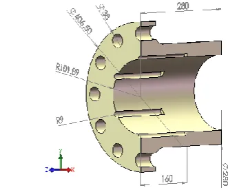
Figure 9. Assembly drawing of the shrink fit designed coupling for the 32 MW rotor generator
As it is resulted, minimum safety factor of applied material in ambient temperature is 1.98. Also it can be resulted that, the values of absolute magnitude in tangentional stress of the coupling and shaft are a little more than calculated values in 145 MW rotor-generator. In the sixth step, by reason of finding the ratio of allowed torque value to the consumed or transferred torque value in the coupling, the following calculations were done.
G G
mech T
P . (13)
sec / 314
60 3000 * 2 60 2
rad n
G
m N
TG 101910.83 .
314 ) 10 ( 32 6
(14)
)] (
) . [(
2 S C pin pin pin
S
all D L n D L
PfD
T (15)
m N Tall
. 8 . 126434
)] 16 . 0 * 018 . 0 * 6 ( ) 27 . 0 * 204 . 0 * 14 . 3 [( *
204 . 0 * 15 . 0 * ) 10 ( 08 . 53 * 5 .
0 6
24 . 1
G all T T
(16)
As it can be seen, the ratio of torques in the 32 MW rotor-generator coupling is approximately 11% lower in comparison with the 145 MW rotor-generator coupling as a pattern for design. This presents lower safety factor for the design coupling. In other word, design of 145 MW rotor-generator coupling is approximately 11% more conservative than the design coupling.
Equation (17) is used for calculating the minimum temperature needed for shrink fit procedure [12].
1
2
2
t D t
C
(17)
C C
t
Min
20 208
204 . 0 * 10 * 12
10 * 23 . 0 * 2
: 6
3 2
4. FEM SIMULATION
In this step, with due attention to the dimensions of the shaft and the chosen dimensions for the coupling of 32 MW rotor-generator, a computer model (CAD) was made and then it was analyzed and assessed with ANSYS software.
Moreover, in real operation conditions designed coupling is a part which is under dynamical conditions and other than static force of shrink fitting, it tolerates other loads, like centrifugal force resulting from rotation and mechanical torques. So in calculations, all of these loads must be entered. While the analytical method
using the theory of thick-walled cylinders only consider the effect of compression force resulted from shrink fitting.
For this reason, computer analysis of the problem is very useful and precise. The accuracy of analytical calculations can be evaluated by using the results of computer analysis. For computer solution by finite element method, designed models were meshed with Solid 187 element and contact element, initially. Then they were loaded. Suitable boundary conditions were applied on them. One of the boundary conditions, used in the model is the centrifugal force. With due attention to the rotation velocity of the shaft and coupling set (3000 rpm), it makes a diametrical expansion in the elastic range of the rotating coupling and approximately some decrease in residual stresses resulting from shrink fitting can be followed in it. In other word, the centrifugal force has a neutralizing effect and/or, it acts opposite to the shrink fitting force. This is considered to be an undesired and inevitable factor in the design process. Another boundary condition is the transferred torque. It is used from the former calculations on the cross-sectional area of the shaft with due attention to the generator consuming power without consideration of the losses resulted from generator efficiency and mechanical losses in the bearings and etc.
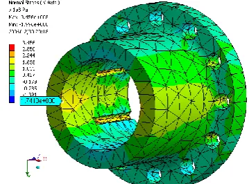
Figure 11. FEM result shows von-Mises stress distribution on the new designed coupling
The third boundary condition applies the relevant supports to show the resistance against rotational torque of the coupling. And it must have degrees of freedom (DOF) in radial direction simultaneously. So it doesn’t prevent the elastic expansion of the shaft and coupling.
Boundary condition of in contact surfaces was considered between the shaft and the coupling, assuming friction factor of 0.15 because of severe friction between two parts [11]. In fact, the main purpose of designing this coupling by shrink fitting method was only this force. In other word, this force is very useful for the aim of transferring the mechanical torque from the coupling to the shaft.
Exerting the mechanical properties, with due attention to the type of following rotor-generator alloy and with due attention to the usage of this material for the coupling with the commercial code of 26NiCrMoV11.5 equivalent to DIN 1.6948, the value of elasticity module in the ambient temperature was considered 200 GPa, and for the Poisson's ratio, it is 0.33. Also the average value of yield strength and ultimate tensile strength were considered 758 MPa and 883 MPa, respectively.
5. CONCLUSION
After the complete solution of problem, the FEM analysis results were investigated as Von-Mises and normal stresses in the directions X and Y that are shown in Figures 6 and 7. According to previous analytical calculations the maximum stress values occurred on the place of cylindrical pins. For example the maximum stress values of the designed 32 MW rotor generator coupling, on the flange side and middle of coupling are respectively 364 and 281 MPa, exactly on the place of cylindrical key pins (Figure 11). It is noticeable that the stress values corresponding to the mentioned points that were calculated by analytical method has small difference with the stress values resulted from FEM simulations, so that this stress values has been calculated equal to 362.5 and 293.4 MPa, respectively for the points on the flange side and middle of coupling. And about the analysis of normal stresses on the boss end of coupling that exactly behaves as a thick cylinder without any geometric discontinuities, the value of normal tensile stress in the X coordinate as tangential direction was calculated 174.13 MPa (Figure 12). During previous analytical calculation the stress value for the corresponding point has been calculated equal to 172.6 MPa without considering the centrifugal load, mechanical torque and friction effect that shows a calculation difference less than 1%.
According to results of problem solution, the maximum stress values was appeared on the place of cylindrical key pins and this place should be under
attention during machining and drilling process to avoid any surface defects due to insufficient surface finishing. This is because this high stress points are very susceptible to crack origination and so on. Hence removing or blending the surface notches and discontinuities of the used raw material is very essential for safety considerations. Meanwhile after the machining process some NDT like UT and MT is useful for final approval.
6. ACKNOWLEDGMENT
The authors would like to thank Mr. Mehrabi, Mr. Hakimi, Mr. Kordi and Mr. Nili for their efforts for making and refurbishing the rotor coupling. In addition, Mr. Mirmiri Tehrani and Mr. Baybordi for their works on rotor dimensioning and technical drawings, and Mr. S. Parsa for his contribution to gathering technical data during this project, and Mr. M. Razi for reviewing the manuscript.
7. REFERENCES
1. Kanisuru, A.M., Bolaji, A.M., Bamidele, A.O. and Olaniran, A.S., "Computer aided design of couplings", International Journal of Engineering (IJE), Vol. 5, No. 5, (2011), 313-332. 2. Farrahi, G., Tirehdast, M., Abad, E.M.K., Parsa, S. and
Motakefpoor, M., "Failure analysis of a gas turbine compressor",
Engineering Failure Analysis, Vol. 18, No. 1, (2011), 474-484. 3. Mohajerani, A. and Farrahi, G., "Numerical investigation of crack orientation in the fretting fatigue of a flat rounded contact", International Journal of Engineering-Transactions B: Applications, Vol. 23, No. 3&4, (2010), 223-232.
4. Klempner, G. and Kerszenbaum, I., "Operation and maintenance of large turbo-generators, John Wiley & Sons, Vol. 14, (2004). 5. Kostyuk, A. and Frolov, V., "Steam and gas turbines", Mir,
Moscow, (1988).
6. Mancuso, J.R. and Jones, R., "Coupling interface connection", in Proceedings of the 30th Turbomachinery Symposium, (2001). 7. Laub, S., "Fretting induced fracture of coupling driven shafts",
(1980).
8. Shigley, J.E., Mischke, C.R., Budynas, R.G., Liu, X. and Gao, Z., "Mechanical engineering design, McGraw-Hill New York, Vol. 89, (1989).
9. API Standard 671, Special purpose couplings for petroleum, chemical, and gas industry services, (1998) Third Edition, American Petroleum Institute, Washington, D.C.
10. Piley, W., Peterson’s stress concentration factors, (1997), John Wiley & Sons Inc., USA.
11. Lingaiah, K., "Machine design databook, McGraw-Hill, Vol. 2, (2003).
Reverse Engineering for Designing the Coupling of a 32 MW
Rotor-generator by Shrink Fitting Method
TECHNICAL NOTE
E. Poursaeidi, M. R. Mohammadi Arhani
Department of Mechanical Engineering, University of Zanjan, Zanjan, Iran
P A P E R I N F O
Paper history:
Received 22 September 2014
Accepted in revised form 03 September 2015
Keywords:
Reverse Engineering Rotor-generator Coupling, Shrink Fitting Stress Analysis Finite Element
هديكچ
نیا شهوژپ دنور یحارط یارب زاب یزاس گنیلپوک بیسآ هدید کی هاگتسد روتور روتارنژ ار هیارا یم دنک . تلع بیسآ
روتور روتارنژ ،روبزم تباصا شکرت یاه کی راجفنا دوب . یحارط هیلوا روتور روتارنژ هب شور گنیجروف هدوب هک سپ زا
نیشام یراک کی روتور هچراپکی اب هیلک تاییزج لصاح هدش دوب . بیسآ یاه هدراو رد یخرب زا یحاون ثعاب هدنک ندش
و شیادج شخب ییاه زا جنلف گنیلپوک هدش دوب . نیاربانب هیحان گنیلپوک هب شور یراکشارت لاماک فذح دیدرگ و کی
گنیلپوک ازجم هتخاس دش و هب شور کنیریش یترارح (
Thermal Shrink
) رب یور روتور روتارنژ نیزگیاج دش . رد
شور زا گنیلپوک یحارط اب هسیاقم
کی گنیلپوک روتور
روتارنژ 541 یتاواگم دش هدافتسا . ادتبا هیلک یاهراب یکیناکم
دوجوم رب یور گنیلپوک یبایزرا دش . تابساحم لماش شور یلیلحت اب هدافتسا زا درادناتسا
ANSI
و هیبش یزاس اب مرن
رازفا
ANSYS
دوب . جیاتن ناشن داد هک اب دوجو تیدودحم ،یسدنه حرط بصن کی گنیلپوک ازجم هب شور کنیریش
یترارح ناکما ریذپ یم دشاب .