1. INTRODUCTION
Vibration control of machines worked by engines has attracted great amount of research activities during last decades. Particular, vehicles motions are influenced by the harmful effects of vibrations caused by engines and roads which have a pivotal role in driver's comfort. Griffin et al. [1], Rokheja [2] and Barak [3] have shown that the interior vibration of a vehicle have a significant effect in comfort and road holding capability. In some previous researches have been shown that the trade-off between comfort and road holding capability is difficult to achieve [4-6]. Today, there are three types of suspension system which are installed between road excitation and vehicle body and named passive suspension, active suspension and semi-active suspension. Passive suspension is composed of a parallel mounting of a spring and damper. This suspension type is commonly used by majority of manufacturers; but it can not compromise between road vehicle comfort and road holding capability, properly. Chalasani has shown that increasing of the passive suspension damping coefficient improves vehicle comfort but this improvement decreases road holding capability [7]. In case of reducing this limitation of passive suspension, the tendency of researchers has led them to produce
other kind of suspension system such as active suspension. Active suspension needs an external energy source. Moreover, it is capable of compromising between road vehicle comfort and road holding capability [8-11]. Thompson has presented that the result of using of active suspension is vibrantly superior to other types of suspension systems [12]. The other type of suspension is called semi-active. This type is halfway between the two other types, passive and active. The semi-active suspension creates an approximate active damping control law without the need of external energy source [13]. Bouazara in his PhD thesis studied three types of suspension system (active, semi-active and passive) for five and eight-degree of freedom vibration model [14]. In his works, Bouazara combined all the performance criteria to form an objective function for an optimization process. For this purpose, he used the weighting coefficients to adjust the comfort and road holding capability criteria in the single optimization design process. Further, he assign the vertical acceleration of seat as vehicle comfort and the relative displacement between sprung mass and tires as road holding capability. Using of weighing coefficients is not a proper approach to solve the multi-objective optimization problems. Because the results of the optimization are extremely depended on the weighing
Optimal Selection of Active Suspension Parameters Using
Artificial Intelligence
M. Salehpour1,*, A. Jamali2and N. Nariman-zadeh3 1P.h.D student, Islamic Azad University, Anzali branch, Anzali, Iran.
2Assistant professor, 3Professor, Faculty of Mechanical engineering, The University of Guilan, Rasht, Iran.
Abstract
In this paper, multi-objective uniform-diversity genetic algorithm (MUGA) with a diversity preserving mechanism called the -elimination algorithm is used for Pareto optimization of 5-degree of freedom vehicle vibration model considering the five conflicting functions simultaneously. The important conflicting objective functions that have been considered in this work are, namely, vertical acceleration of seat, vertical velocity of forward tire, vertical velocity of rear tire, relative displacement between sprung mass and forward tire and relative displacement between sprung mass and rear tire. Further, different pairs of these objective functions have also been selected for 2-objective optimization processes. The comparison of the obtained results with those in literature demonstrates the superiority of the results of this work. It is shown that the results of 5-objective optimization include those of 2-objective optimization and, therefore, provide more choices for optimal design of vehicle vibration model.
Keywords:Vehicle vibration model; Pareto; MUGA; Genetic algorithm; Multi-objective optimization
İ
coefficients and with the slight changing in the value of coefficients, the results would be different. Feng et al. adopted a combined control scheme for the vertical motion optimization of active vehicle suspension systems using a genetic algorithm based self-tuning PID controller and a fuzzy logic controller [15]. Alkhatib applied genetic algorithm (GA) method to the optimization problem of a linear one-degree of freedom (1-DOF) vibration isolator mount and the method was extended to the optimization of a linear quarter car suspension model [16]. The optimum solution was obtained numerically by utilizing GA and employing a cost function that sought minimizing absolute acceleration RMS (root mean square) sensitivity to changes in relative displacement RMS. Gündoðdu presented an optimization of a four-degree of freedom quarter car seat and suspension system using genetic algorithms to determine a set of parameters to achieve the best performance of the driver [17]. The desired objective was proposed as the minimization of a multi-objective function formed by the combination of not only suspension deflection and tire deflection but also the head acceleration and crest factor (CF), which is not practiced as usual by the designers. Nariman-zadeh et al. used a multi-objective approach for optimal design of a 5-degree of freedom vehicle vibration model with passive suspension [18]. In this reference, they obtained some Pareto fronts of dominated optimal design points of five non-commensurable objective functions, namely, vertical acceleration of seat, vertical velocities of forward and rear tires, relative displacements between sprung mass and both forward and rear tires.
In this paper, multi-objective uniform-diversity genetic algorithm (MUGA) with a diversity preserving mechanism called the å-elimination algorithm is used for multi-objective optimization of a 5-degree of freedom vehicle vibration model. The conflicting objective functions that have been considered for minimization are, namely, vertical acceleration of seat ( ), vertical velocity of forward tire ( ), vertical velocity of rear tire ( ), relative displacement between sprung mass and forward tire (d1) and relative displacement between sprung mass and rear tire (d2). The design variables used in the
optimization of vibration are, namely, seat damping
coefficient(css), vehicle suspension damping
coefficient (cs1and cs2), seat stiffness coefficient (kss), vehicle suspension stiffness coefficient (ks1 and ks2),
damping coefficients for the active suspension (g1and g2) and seat position in relation to the center of mass (r).Various pair-wise 2-objective optimization and 5-objective optimization processes are performed. The inclusion of the results by 5-objective optimization is verified using the results of different 2-objective optimization processes through some overlay graphs of the Pareto fronts. Prominently, it is shown that a trade-off optimum design can be verified from those Pareto fronts obtained by multi-objective optimization process. Finally, the superiority of time domain vibration performance of such design point is shown in comparison with those given in the literature.
2. MULTI-OBJECTIVE PARETO OPTIMIZATION
Multi-objective optimization that is also called multi-criteria optimization or vector optimization has been defined as finding a vector of decision variables satisfying constraints to give optimal values to all objective functions [21-22]. In general, it can be mathematically defined as:
find the vector to optimize
(1)
subject to m inequality constraints
(2)
and pequality constraints
(3)
where, is the vector of decision or design
variables, and is the vector of objective
functions. These objectives often conflict with each other so that improving one of them will deteriorate another .Therefore; there is no single optimal solution as the best with respect to all the objective functions. Instead, there is a set of optimal solutions, known as Pareto optimal solutions or Pareto front for multi-objective optimization problems [23-24].
Some unique natural properties of evolutionary algorithms like their parallel or population-based search scheme have been reasons to use them for multi-objective optimization problems. It should be noted that keeping the genetic diversity in the population or the Pareto front is one of the important
k
X
F( )
n X*
p to 1 j , 0 ) (X
hj ,
m to i X
li( )d0 , 1 ,
>
@
Tk X
f X f X f X
F( ) 1( ), 2( ),..., ( ) ,
>
@
Tn x x x
X * *
2 * 1 *
,..., ,
2
z
1
z
c z
and main issue of these methods [21-22, 24-25]. The Pareto-based approach of NSGA-II [24] has been used in a wide range of engineering MOPs because of its simple yet efficient non-dominance ranking procedure in yielding different levels of Pareto frontiers. However, the crowding approach in such a state-of-the-art MOEA [25] works efficiently for two objective optimization problems as a diversity-preserving operator which is not the case for problems with more than two objective functions [18-20].
In this work, a recently reported multi-objective uniform-diversity genetic algorithm method called MUGA [18-20] is used for the multi-objective optimal design of vehicle vibration model. MUGA uses
non-dominated sorting mechanism together with a
-elimination diversity preserving algorithm to get Pareto optimal solutions of MOPs more precisely and uniformly. In fact, the basic idea of sorting of non-dominated solutions originally proposed by Goldberg [26] which has been used in different evolutionary multi-objective optimization algorithms, more importantly in NSGA II by Deb [24], has been adopted here. In order to improve the genetic diversity among the population, the -elimination diversity approach
is used in which all the clones and -similar
individuals are recognized and simply eliminated from population. Therefore, based on a value of as the elimination threshold, all the individuals in a front within this limit of a particular individual are eliminated. More detailed description of MUGA such
as pseudo code of main algorithm, -elimination
algorithm and etc., can be found in [18-20].
3. MULTI-OBJECTIVE OPTIMIZATION OF VEHICLE VIBRATION MODEL
A 5-degree of freedom vehicle with active suspension which is adopted from reference [14] is shown in Figure 1. This model is composed of one sprung mass that joints to three unsprung masses (indicate the tires and seat). Moreover, effect of degrees of freedom, linear motion (in vertical direction for sprung and unsprung masses), and rotating motion (pitching motion) for sprung mass ,in terms of acceleration, velocity and movement, are exerted in formulation of motion equations. M1, m2,
mc, ms, Is, kp1, kp2, l1and l2which denote vehicle fixed parameters are expressed as forward tire mass, rear tire mass, seat mass, sprung mass, momentum inertia
of sprung mass, forward tire stiffness coefficient , rear tire stiffness coefficient, forward and rear suspensions position in relation to the center of mass, respectively. Design variables kss, ks1and ks2, css, cs1and cs2, g1and ,g2 and r denote seat stiffness coefficient, stiffness coefficients for vehicle suspension, seat damping coefficient, damping coefficients for vehicle suspension, damping coefficients for the active suspension and seat position in relation to the center of
mass, respectively. g1 and g2 are the damping
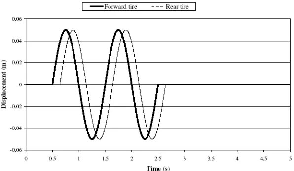
coefficients for the active suspensions obtained by the solution of Riccati equation [27]. Further, Subscripts 1 and 2 indicate tire axes, respectively. It is also necessary to observe that in this case study, seat type is composed of a linear spring and damper. This model is excited by a double-bump shown in figure 2.
The differential linearized equations of motion, with respect to the degrees of freedom and for small
angle , are derived by the use of Newton-Euler
equations and can be written as follows [14]:
(4)
(5)
(6)
(7)
(8) 2
2
2 s
a g z
F
1 1
1 s
a gz
F
T
2
2 z l
zs s
T
1
1 z l
zs s
T
r zzps s
T
İ
İ
İ
İ
İ
Fig. 1.Vehicle vibration five-degree of freedom model with active suspension adopted from reference [14](9)
(10)
(11)
(12)
(13)
(14)
(15)
(16)
Where zc, zs, zsiand are vertical seat displacement, vertical displacement of the Central Gravity of the sprung mass, vertical displacement of the ends of the sprung mass and rotating motion (pitching motion),
respectively. Further, represent
vertical seat velocity, vertical tires velocity and vertical velocity of the ends of the sprung mass,
respectively. denote vertical seat
acceleration, vertical acceleration of the Central Gravity of the sprung mass, vertical tires acceleration and rotating acceleration (pitch acceleration), respectively. The damping force generated is given as follow [14]:
(17)
Lastly, zp1and zp2represent the excitation via road double bumps, as shown in figure 2.
It is supposed that the vehicle moves at constant velocity =20m/s over double bump, and it is further assumed that the rear tire follows the same trajectory
as the front tire with a delay of . The
input values of fixed parameters are presented at Table 1 [14].
In this paper, 50000<kss(N/m)<150000,
10000<ks1(N/m)<20000, 10000<ks2(N/m)<20000, 1000<css(Ns/m)<4000, 500<cs1(Ns/m)<2000,
500<cs2(Ns/m)<2000, 500<g1,g1(Ns/m)<2000 and
0<r<0.5 are observed as design variables to be
v l l t ( f v)/
'
v
sj j
aj g z
F
c
Z , zs, zi and T c
z , zi and zsi
T
)
( 2 2
2 2
2 s p p
sz F k z z
m
)
( 1 1
1 1
1 s p p
sz F k z z
m
ss s s
s lF lF rF
I
T
1 1 2 2ss s s s
sz F F F
m 1 2
ss c
cz F
m
) (
)
( 2 2 2 2 2
2
2 k z z c z z
Fs s s s s
) ( )
( 1 1 1 1 1
1
1 k z z c z z
Fs s s s s
) (
)
( c ps ss c ps
ss
ss k z z c z z
F
Fig. 2. Double bumps excitation
1
l 1.011 m
2
l 1.803 m
1
m 40 kg
2
m 35.5 kg
c
m 75 kg
s
m 730 kg
s
I 1230 kg.m2
1 p
k 175500 N /m
2 p
k 175500 N /m
Table 1.The input values of fixed parameters of this paper
optimally found based on multi-objective optimization of 5 different objective functions, namely, vertical acceleration of seat ( ), vertical velocity of forward tire( ), vertical velocity of rear tire ( ), relative displacement between sprung mass and forward tire (d1) and relative displacement between sprung mass and rear tire (d2).
4. TWO-OBJECTIVE OPTIMIZATION OFVEHICLE VIBRATION MODEL
In this section, MUGA is used for multi-objective design of vehicle model which has been shown in Figure 1. For this purpose, five different pairs out of ten possible pairs of objectives are considered in bi-objective optimization processes. Such pairs of objectives to be optimized separately have been chosen as ( , ), ( , ), ( ,d1), ( ,d2) and (d1, d2) which stands for vertical acceleration of seat with vertical velocity of forward tire, vertical velocity of rear tire, relative displacement between sprung mass and forward tire, and relative displacement between sprung mass and rear tire and relative displacement between sprung mass and forward tire with relative displacement between sprung mass and rear tire ,respectively. Evidently, it can be observed that all of the objective functions are minimized in those sets of objective functions. A population of 80 individuals with a crossover probability of 0.9 and mutation probability of 0.1 has been used in 240 generations. Pareto fronts of each chosen pair of two objectives
have been shown through figures 3-7. It is clear from all of the figures that obtaining a better value of one objective would normally cause a worse value of another objective. However, if the set of decision variables is selected based on each of a Pareto front, it will lead to the best possible combination of that pair of objectives. In other words, if any other set of decision variables is chosen, the corresponding values of pair of objectives will locate a point inferior to the corresponding Pareto front. Such inferior area in the space of the objective functions for figures 3-7 are in fact top/right sides.
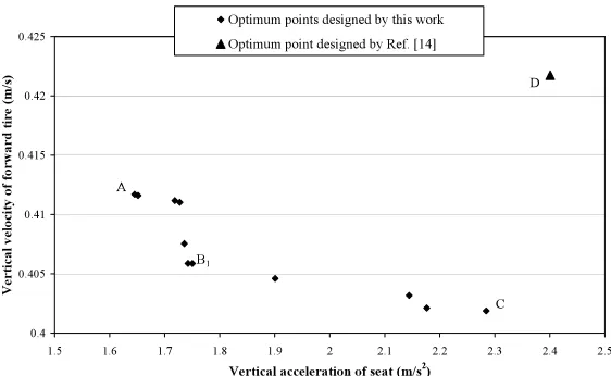
Figure 3 depicts the Pareto front of vertical acceleration of seat and vertical velocity of forward tire representing different non-dominated optimum points with respect to the conflicting objectives. In this figure, points A and C stand for the best vertical acceleration of seat and the best vertical velocity of forward tire, respectively. It should be noted that all the optimum design points in this Pareto fronts are non-dominated and could be chosen by a designer. It is clear from this figure that choosing a better value for any objective function in these Pareto fronts would cause a worse value of another objective function. Clearly, there are some important optimal design facts between these objective functions that can readily be observed in that Pareto front. Such important design facts could not have been found without the use of Pareto optimization approach of vehicle vibration
model. In figure 3, point B1 is the point which
demonstrates an important optimal design fact. c
z c z 2
z c
z
1
z c z
2
z
1
z
c z
0.4 0.405 0.41 0.415 0.42 0.425
1.5 1.6 1.7 1.8 1.9 2 2.1 2.2 2.3 2.4 2.5
Vertical acceleration of seat (m/s2
)
Vertical vel
ocity of forward tire (m
/s)
Optimum points designed by this work
Optimum point designed by Ref. [14]
A
C B1
D
Fig. 3. Pareto front for vertical acceleration of seat and vertical velocity of forward tire in 2-objective optimization
0.418 0.42 0.422 0.424 0.426 0.428 0.43 0.432 0.434 0.436
1.5 1.7 1.9 2.1 2.3 2.5 2.7 2.9
Vertical acceleration of seat (m/s2)
Vertical velocity of rear ti
re (m)
Optimum points designed by this work
Optimum point designed by Ref. [14]
A
B2
E D
Fig. 4. Pareto front for vertical acceleration of seat and vertical velocity of rear tire in 2-objective optimization
0.065 0.07 0.075 0.08 0.085 0.09
1.565 1.665 1.765 1.865 1.965 2.065 2.165 2.265 2.365 2.465
Vertical acceleration of seat (m/s2)
Relati
v
e displacem
e
nt b
e
tween
sprung m
a
ss and
fo
rw
ard t
ire
(m)
Optimum points designed by this work
Optimum point designed by Ref. [14] A
B3
F
D
Fig. 5. Pareto front for vertical acceleration of seat and relative displacement between sprung mass and forward tire in 2-objective optimization
0.035 0.04 0.045 0.05 0.055 0.06 0.065 0.07 0.075
1.5 1.7 1.9 2.1 2.3 2.5 2.7
Vertical acceleration of seat (m/s2)
Relati
v
e displacem
e
nt b
e
tween sprung m
a
ss and
re
ar
tire
(m)
Optimum points designed by this work
Optimum point designed by Ref. [14] A
B4
G D
Fig. 6. Pareto front for vertical acceleration of seat and relative displacement between sprung mass and rear tire in 2-objective optimization
Optimum design point B1 obtained in this paper
exhibits a small increase in forward tire velocity in comparison with that of point C (the design with the least vertical velocity of forward tire) whilst its vertical seat acceleration improves about 23%. In fact,
trade-off design point, B1, would not have been
obtained without the use of the Pareto optimum approach presented in this paper.
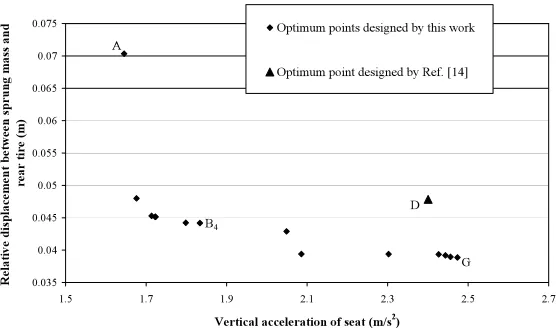
Such non-dominated Pareto fronts of the other chosen sets of objective functions have been shown through figures 4-7. As considered in these figures, point A stands for the best vertical acceleration of seat whilst points E, F and G represent the best , d1and
d2, respectively. Similarly, the trade-off designing
points B2, B3 and B4 are the design points which
demonstrate the important optimal design fact. With more careful observation, it is found that the values of seat accelerations improve about 32%, 13% and 26% with a small increase in other objective functions from points E to B2, F to B3and G to B4in figures 4, 5 and
6, respectively. In all these figures, point D represents the optimum design obtained in reference [14] which it is very evident that is vigorously dominated by all Pareto fronts shown in these figures. It is necessary to observe that in figure 7 point F represents optimum point from both two objective functions, and further shows less values comparing to point D.
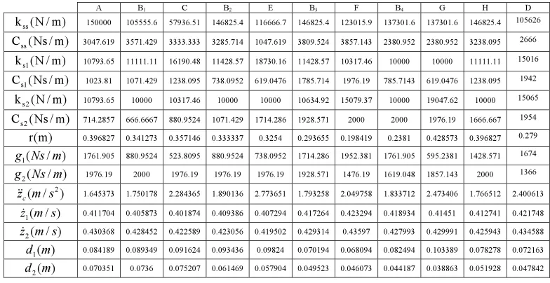
The corresponding values of objective functions and design variables of these optimum design points and the point one in reference [14] are given in Table 2. 2 z 0.038 0.04 0.042 0.044 0.046 0.048 0.05
0.065 0.07 0.075 0.08 0.085 0.09 0.095 0.1 0.105 0.11
Relative displacement between sprung mass and forward tire (m)
Relative disp
la
cement betwee
n sprung mass
an d rear ti re ( m )
Optimum points designed by this work
Optimum point designed by Ref. [14] F
G D
Fig. 7. Pareto front for relative displacement between sprung mass and forward tire and relative displacement between sprung mass and rear tire in 2-objective optimization
D H G B4 F B3 E B2 C B1 A 105626 146825.4 137301.6 137301.6 123015.9 146825.4 116666.7 146825.4 57936.51 105555.6 150000 ) m / N ( kss 2666 3238.095 2380.952 2380.952 3857.143 3809.524 1047.619 3285.714 3333.333 3571.429 3047.619 ) m / Ns ( Css 15016 11111.11 10000 10000 10317.46 11428.57 18730.16 11428.57 16190.48 11111.11 10793.65 ) m / N ( ks1
1942 1238.095 619.0476 785.7143 1976.19 1785.714 619.0476 738.0952 1238.095 1071.429 1023.81 ) m / Ns ( Cs1
15065 10000 19047.62 10000 15079.37 10634.92 10000 10000 10317.46 10000 10793.65 ) m / N ( ks2
1954 1666.667 1976.19 2000 2000 1928.571 1714.286 1071.429 880.9524 666.6667 714.2857 ) m / Ns ( Cs2
0.279 0.396827 0.428573 0.2381 0.198419 0.293655 0.3254 0.333337 0.357146 0.341273 0.396827 ) m ( r 1674 1428.571 595.2381 1761.905 1952.381 1714.286 738.0952 880.9524 523.8095 880.9524 1761.905 ) / (
1 Ns m
g 1366 2000 1857.143 1619.048 1476.19 1928.571 1976.19 1976.19 1976.19 2000 1976.19 ) / (
2 Ns m
g 2.400613 1.766512 2.473406 1.833712 2.049758 1.793258 2.773651 1.890136 2.284365 1.750178 1.645373 ) / ( 2 s m zc
0.421748 0.412741 0.41451 0.418934 0.423294 0.417264 0.407294 0.409386 0.401874 0.405873 0.411704 ) / (
1m s
z 0.434588 0.425943 0.429991 0.427993 0.43597 0.429314 0.419502 0.423056 0.422589 0.428452 0.430368 ) / (
2 m s
z 0.072163 0.078278 0.103389 0.082494 0.068094 0.070194 0.09824 0.093436 0.091624 0.089349 0.084189 ) ( 1m d 0.047842 0.051928 0.038863 0.044187 0.046073 0.049523 0.057904 0.061469 0.075207 0.0736 0.070351 ) ( 2 m d
Table 2.The values of objective functions and their associated design variables of the optimum points of this work and the one of reference [14]
The Pareto optimum approach of this paper reveals some interesting and informative design aspects that may not have been found without multi-objective optimization. However, all such important and worthy information regarding the trade-off design point can also be simply discovered using a five-objective Pareto optimization instead of five separate bi-objective optimization processes.
5. FIVE-OBJECTIVE OPTIMIZATION OF VEHICLE VIBRATION MODEL
A multi-objective optimization design of vehicle model including all five objectives simultaneously can offer more choices for a designer. Moreover, such 5-objective optimization can subsume all the 2-5-objective optimization results presented in the previous section. This will allow finding a trade-off optimum design points from the view of all five objective functions simultaneously. Therefore, in this section, five objective functions, namely, vertical acceleration of
seat ( ), vertical velocity of forward tire ( ),
vertical velocity of rear tire ( ), relative displacement between sprung mass and forward tire (d1) and relative
displacement between sprung mass and rear tire (d2)
are chosen for multi-objective optimization in which all of them are minimized simultaneously. A population of 80 individuals with a crossover probability of 0.9 and mutation probability of 0.1 has been used in 240 generations.
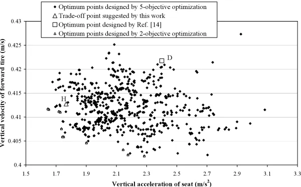
Figure 8 depicts the non-dominated individuals of
5-objective optimization in the plane of ( - ) together with the results to 2-objective optimization found in previous section. Such non-dominated individuals of both 5 and 2-objective optimization have alternatively been shown in the plane of ( - ), ( -d1), ( -d2) and (d1-d2) through figures 9-12, respectively. It should be noted that there is a single set of individuals as a result of 5-objective optimization of , , , d1 and
d2that are shown in different planes together with the corresponding 2-objective optimization results. Therefore, there are some points in each plane that may dominate others in the case of 5-objective optimization. However, these individuals are all non-dominated when considering all five objectives simultaneously. By careful investigation of the results of 5-objective optimization in each plane, the Pareto fronts of the corresponding two-objective optimization previously found can now be observed in these figures. It can readily be observed that the results of such 5-objective optimization include the Pareto fronts of each 2-objective optimization and provide, therefore, more optimal choices for the designer.
It is now desired to obtain an optimum design point out of all non-dominated 5-objective optimization process somehow satisfying all five objective functions. In other words, each of the obtained design points given in previous section is acceptable based on pertinent two objective functions, but there is no reason that such an optimum design point existed in one of the Pareto fronts (i.e. plane of ( - )) is located in the other Pareto fronts too (i.e. plane of (zc-z2)).
1
z
c z
2 z
1
z
c
z
c
z
c
z
2
z
c
z
1 z
c z
2 z
1 z c
z
0.4 0.405 0.41 0.415 0.42 0.425 0.43
1.5 1.7 1.9 2.1 2.3 2.5 2.7 2.9 3.1 3.3
Vertical acceleration of seat (m/s2)
Vertic
al veloci
ty of forward tire (m
/s)
Optimum points designed by 5-objective optimization Trade-off point suggested by this work
Optimum point designed by Ref. [14]
Optimum points designed by 2-objective optimization
H
D
Fig. 8. Vertical acceleration of seat with vertical velocity of forward tire in both 5-objective & 2-objective optimization.
0.415 0.42 0.425 0.43 0.435 0.44 0.445
1.5 1.7 1.9 2.1 2.3 2.5 2.7 2.9 3.1 3.3
Vertical acceleration of seat (m/s2)
Verti
cal
velocity of rear tire (m/s)
Optimum points designed by 5-objective optimization
Trade-off point suggested by this work
Optimum point designed by Ref. [14]
Optimum point designed by 2-objective optimization
H
D
Fig. 9. Vertical acceleration of seat with vertical velocity of rear tire in both 5-objective & 2-objective optimization
0.06 0.07 0.08 0.09 0.1 0.11 0.12 0.13
1.5 1.7 1.9 2.1 2.3 2.5 2.7 2.9 3.1 3.3
Vertical acceleration of seat (m/s2)
Relative d
isp
lacemne
t be
twe
en
sp
run
g m
a
ss and
forward tire (m
)
Optimum points designed by 5-objective optimization
Trade-off point suggested by This work
Optimum point designed by Ref. [14]
Optimum points designed by 2-objective optimization
H
D
X
Fig. 10. Vertical acceleration of seat with relative displacement between sprung mass and forward tire in both 5-objective & 2-objective optimization
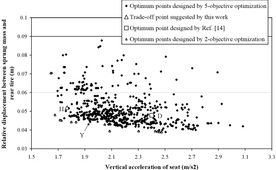
0.03 0.04 0.05 0.06 0.07 0.08 0.09 0.1
1.5 1.7 1.9 2.1 2.3 2.5 2.7 2.9 3.1 3.3
Vertical acceleration of seat (m/s2)
Relative
displacem
e
nt between
sprung m
a
ss and
rear
tire
(m)
Optimum points designed by 5-objective optimization Trade-off point suggested by this work
Optimum point designed by Ref. [14]
Optimum points designed by 2-objective optmization
H
D
Y
Fig. 11. Vertical acceleration of seat with relative displacement between sprung mass and rear tire in both 5-objective & 2-objective optimization
It is now possible to seek an optimum design point which is located almost on all Pareto fronts of figures 8 through 12. This can be simply achieved by mapping of the values of objective functions of all non-dominated points into interval 0 and 1. Using the sum of these values for each non-dominated points, the design point H simply represents the minimum of those values. It can be seen that the design point H located on all Pareto fronts approximately. Moreover, it can be seen that in two planes (( - ) and ( -)) point H dominates point D proposed by reference [14]; in two planes (( -d1) and ( -d2)), no one
dominates together and only in the last plane, point D dominate point H. But with a careful observation, it could be inferred that there are several optimum points designed by 2 & 5-objective optimization in these
three planes that dominate point D (i.e. points X, Y and Z in figures 10 through 12).
It should be noted that time response behavior of vertical acceleration of seat of proposed optimum point of this work and the one of reference [14] of vertical acceleration of seat are shown in figure 13. It is clear that time response behavior of point H is superior to that of point D. The values of objective functions and their associated design variables of H are shown in Table 2. The comparison of the values of objective functions associated with the optimum point H obtained from 5-objective functions optimization with those of 2-objective functions optimization of design points B1,
B2, B3, B4 and F given in Table 2 demonstrates the relative superiority of design point H.
Therefore, such multi-objective optimization of c
z
c
z
2
z
c
z
1
z
c z
0.03 0.04 0.05 0.06 0.07 0.08 0.09 0.1
0.06 0.07 0.08 0.09 0.1 0.11 0.12 0.13
Relative displacement between sprung mass and forward tire (m)
Re
lative displacement betwee
n sprung mass an
d
rear t
ire (
m
)
Optimum points designed by 5-objective optimization
Trade-off point suggested by this work
Optimum point desugned by Ref. [14]
Optimum points designed by 2-objective optmization
D H
Z
Fig. 12. Relative displacement between sprung mass and forward tire with relative displacement between sprung mass and rear tire in both 5-objective & 2-objective optimization
-2.5 -2 -1.5 -1 -0.5 0 0.5 1 1.5 2 2.5
0 0.5 1 1.5 2 2.5 3 3.5 4 4.5 5
Time (s)
V
e
rt
ic
al accel
erat
ion
of
seat
(m
/s
2)
Time response behavior of trade-off point suggested by this work
Time response behavior of optimum point designed by Ref. [14]
Fig. 13. Comparison of time response behavior of vertical acceleration of seat between points H, D
vertical acceleration of seat ( ), vertical velocity of forward tire ( ), vertical velocity of rear tire ( ), relative displacement between sprung mass and forward tire (d1) and relative displacement between
sprung mass and rear tire (d2) provide optimal choices of design variables based on Pareto non-dominated points.
6. CONCLUSION
A multi-objective uniform-diversity genetic
algorithm (MUGA) with a diversity preserving ability was used to optimally design of vehicle vibration model. The objective functions which conflict with each other were selected as vertical acceleration of
seat ( ), vertical velocity of forward tire ( ),
vertical velocity of rear tire ( ), relative displacement between sprung mass and forward tire (d1) and relative displacement between sprung mass and rear tire (d2). The multi-objective optimization of vehicle model led to the discovering some important trade-offs among those objective functions. The superiority of the obtained optimum design points was shown in comparison with those reported in literature. Such multi-objective optimization of vehicle model could unveil very important design trade-offs between conflicting objective functions which would not have been found otherwise. Further, it has been shown that the results of 5-objective optimization include those of 2-objective optimization in terms of Pareto frontiers and provide, consequently, more choices for optimal design.
REFERENCES
[1]. Griffin, M., Parsons, K., Whitham, E., 1982.
Vibration and comfort. IV. Application of experimental results. Ergonomics 25, 721–739.
[2]. Rakheja, S., 1985. Computer-aided Dynamic
Analysis and Optimal Design of Suspension Systems for Off-road Tractors. PhD Thesis. Concordia University, Canada.
[3]. Barak, P., 1991. Magic numbers in design of
suspensions for passenger cars. Passenger Car Meeting, Tennesee, SAE Paper 911921, pp. 53–88.
[4]. Karnopp, D., 1989. Analytical results for
optimum actively damped suspensions under random excitation. ASME Journal of Vibration,
Acoustics, Stress, and Reliability in Design 111 (July), 278–283.
[5]. Hac, A., Youn, I., 1992. Optimal semi-active
suspension with preview based on a quarter car model. ASME Journal of Vibration and Acoustics 114, 84–92.
[6]. Baumal, A.E., McPhee, J.J., Calamai, P.H.,
1996. Genetic algorithm optimization for active vehicle suspension design, in: CSME Congress, pp. 455–464.
[7]. Chalasani, R.M., 1986. Ride performance
potential of active suspension systems part 1: Simplified analysis based on a quarter-car model, in: Symposium on Simulation and Control of Ground Vehicles and Transportation Systems AMD-80 (DSC.2), pp. 187–204. [8]. Bouazara, M., Richard, M.J., 1996. An optimal
design method to control the vibrations of suspensions for passenger cars, in: International Mechanical Engineering Congress and Exposition: The Winter Annual Meeting of ASME, Atlanta, DSC 58, pp. 61–68.
[9]. Hrovat, D., 1991, Optimal active suspensions
for 3d vehicule models. In: Proceedings of the American Control Conference, vol. 2, Arizona, USA, pp. 1534–1541.
[10]. Goodall, R.M., Kortüm, W., 1983. Active control in ground transportation – a review of the state-of-the-art and future potential. Vehicle System Dynamics 12, 225–257.
[11]. Yi, K., Hedrick, J.K., 1992. The use of semi-active suspensions to reduce pavement damage, in: Henry, J.J., Wamblod, J.C. (Eds.), Vehicle, Tire, Pavement Interface, ASTM STP 1164, American Society for Testing and Materials, Philadelphia, pp. 1–13.
[12]. Thompson, A.G., 1989. The effect of tire damping on the performance of vibration absorbers in an active suspension. ASME Journal of Sound and Vibration 133 (3), 457–465.
[13]. Redfield, R.C., 1991. Performance of low-bandwidth, semi-active damping concept for suspension control. Vehicle System Dynamics 20, 245–267.
[14]. Bouazara, M., 1997. Etude et Anaslyse de la Suspension Active et Semi-active des Vehicules Routters. Ph.D. Thesis, Universite Laval, Canada.
2
z
1
z c
z
2 z
1 z
c z
[15]. Feng, J. Z., LI, J., and YU, F., 2003. GA-based PID and Fuzzy Logic control for active vehicle suspension system. International Journal of Automotive Technology 4 (4), 181-191. [16]. Alkhatib, R., Nakhaie Jazar, G., Golnaraghi,
M.F., 2004. Optimal design of passive linear suspension using genetic algorithm. Journal of Sound and Vibration 275, 665–691.
[17]. Ö. Gündoðdu, 2007.Optimal seat and suspension design for a quarter car with driver model using genetic algorithms, International Journal of Industrial Ergonomics 37 (4), 327-332.
[18]. Nariman-Zadeh, N., Salehpour, M., Jamali, A., Haghgoo, E., 2010. Pareto optimization of a five-degree of freedom vehicle vibration model using a multi-objective uniform-diversity genetic algorithm (MUGA). Engineering Applications of Artificial Intelligence 23(4), 543-551, 2010.
[19]. Jamali, A., Nariman-Zadeh, N., Atashkari, K., 2008. Multi-objective Uniform diversity Genetic Algorithm (MUGA), In Advanced in Evolutionary Algorithms, witold kosinski (Ed.), IN-TECH, Vienna.
[20]. Jamali, A., Hajiloo, A., Nariman-zadeh, N., 2010. Reliability-based robust Pareto design of linear state feedback controllers using a multi-objective uniform- diversity genetic algorithm (MUGA). Expert Systems with Applications 37 (1), 401–413.
[21]. Nariman-Zadeh, N., Atashkari, K., Jamali, A., Pilechi, A., Yao, X., 2005. Inverse modeling of multi-objective thermodynamically optimized turbojet engine using GMDH-type neural networks and evolutionary algorithms. Engineering Optimization 37 (26), 437–462. [22]. Coello Coello, C.A., Becerra, R.L., 2003.
Evolutionary multi-objective optimization using a cultural algorithm. In: Swarm, IEEE (Ed.), Intelligence Symposium, IEEE Service Center, Piscataway, pp. 6–13.
[23]. Diwekar, U.M., Kalagnaman, J.R., 1997. Efficient sampling technique for optimization under uncertainty. American Institute of Chemical Engineering Journal 43 (2) 440-447. [24]. Deb, K., Agrawal, S., Pratap, A., Meyarivan, T.,
2002. A fast and elitist multi- objective genetic algorithm: NSGA-II. IEEE Transactions on
Evolutionary Computation 6 (2), 182–197. [25]. Coello Coello, C.A., Van Veldhuizen, D.A.,
Lamont, G.B., 2002. In: Evolutionary Algorithms for Solving Multi-Objective Problems. Kluwer Academic, Dordrecht. [26]. Goldberg, D.E., 1989. Genetic algorithms in
search, Optimization, and Machine Learning. Addison-Wesley, Reading, MA.
[27]. Bouazara, M., 1991. L’influence des paramètres de suspension sur le comportement d’un véhicule. Master’s thesis. Universite Laval, Canada.
![Fig. 1. Vehicle vibration five-degree of freedom modelwith active suspension adopted from reference [14]](https://thumb-us.123doks.com/thumbv2/123dok_us/8950361.1859729/3.595.306.528.79.269/vehicle-vibration-degree-freedom-modelwith-suspension-adopted-reference.webp)