Optimization of a Reinforced-flat End Cap Through
An-alytical Study and Genetic Algorithm
A.R. Hosseinzadeh
∗, M. Ebrahimi, H. Sodagari, A.R. Abedian
Air Cooled Condensate Group, Mechanical Engineering Department, Monenco Iran Consulting Engineers, Iran.
Article info
Article history:
Received 09 June 2019 Received in revised form 03 July 2019
Accepted 27 July 2019
Keywords:
Flat end cap Pressure vessel Finite element Kuhn-Tucker Genetic algorithm
Abstract
An efficient design is a key factor in final expenditure of a certain construction. Pressure vessels are structures that play an indispensable role in different industries such as petroleum, power plants etc. Pressure vessels are receptacles often used to keep gases or liquids at a pressure typically different from what atmospheric pressure is. End caps which close the end of vessels can be formed in different shapes. Thus, end cap design also has a significant role in the integrity of vessels to prevent fatal accidents that are frequent in the pressure vessel’s history. In this study, an extensive investigation of huge-flat end caps under external pressure was carried out to extract the most efficient geometrical layout. This kind of flat end cap is an essential part of the designed main duct in the Air Cooled Condenser (ACC) systems as a configuration that renders steam to condensed water inside a definite arrangement of finned tubes in a hybrid thermal power plant. To determine an optimized state of stresses considering weight limitation, a number of finite element models were simulated. The simulations were performed in a relatively wide domain of two geometrical variables, namely thickness and height of stiffeners. By constituting a comprehensive data library, an objective function was formed using the results of finite element. The procedure was followed through a genetic algorithm to find an optimized stress state. An analytical study was also accomplished to reach an optimized end cap resulting in the lowest stress level. The findings showed very similar results for the two methods. Furthermore, a profound observation of the influence of two geometrical parameters was conducted in different weight limits. Although this study is based on a particular actual-industrial problem in an implemented power plant, the proposed method and results are applicable to a great number of similar cases.
1. Introduction
Pressure vessels are extensively employed in industries for processing and storage of fluids and steams at differ-ent operating temperatures and pressures. Storage and transportation tanks, thin and thick-walled vessels, are the most frequent types of vessels. If the diameter of vessel is equal to or more than 10 times the thickness of
the wall, it is typically called thin-walled vessels; oth-erwise it is known as thick-walled. Storage tanks are usually known for their significantly thin walls, it is for the simple reason that the dead-sustained loads are the only ones that they are capable to tolerate. Ves-sels for transportation are thin-walled ones produced in large size [1]. Appropriate design procedure has a significant importance in protecting the vessels from
∗Corresponding author: Dr. A.R. Hosseinzadeh
E-mail address: [email protected] http://dx.doi.org/10.22084/jrstan.2019.19345.1095 ISSN: 2588-2597
explosion which could lead to injury of humans and also destruction of designed setups. Although an ap-propriate design requires a reasonable range of stresses [2], an economic design is worthwhile through reduc-ing the weight of structures. Therefore, makreduc-ing an ap-propriate compromise between weight and stresses is a challenge during engineering designs.
A spherical shape is the most reliable configuration for a pressure vessel. Inherently, the pressure inside a pressure vessel tries to bend the walls out. Thus, due to its symmetrical and subsequently stable shape, a spherical vessel is claimed to be able to tolerate the most internal and external loads [3]. In spite of mer-its involved with using spherical vessel, mer-its producing is rather formidable and not economical. As a conse-quence, the majority of pressure vessels are formed in shape of cylinder which can be equipped with differ-ent types of caps on each end. At the same time, end cap plays a significant role in the lifetime of the entire vessel’s structure and its integrity. These end caps are typically categorized as ellipsoidal, spherically dished (torispherical), hemispherical, conical, tori-conical and flat ones. The internal capacity of end caps is directly related to the cost of each type of end cap. In this way, hemispherical end caps have greater internal volumes compared to ellipsoidal ones, which have greater inter-nal volumes than spherically dished end caps. Blunt or flat end cap is the most critical type of the end caps whose design needs a careful examination. Undoubt-edly, the optimum design can be accomplished through the use of a correct arrangement of reinforcement. It is also noteworthy to mention that vessels under exter-nal pressure shall meet more requirements in compar-ison with internal-pressured vessels [4]. In the current study, the former type has been focused on.
Hassan et al. [5] has proposed a method for opti-mization of pressure vessels by investigating numerous parameters such as thickness, length and radius of the shell through a rather new technique called Ant Colony Optimization algorithm (ACO). In this study, an at-tempt has been made to suggest a method to minimize weight and to improve the strength of the structure simultaneously.
In another study, a weight minimization has been performed in a hydrogen storage vessel using an adap-tive genetic algorithm [6]. The burst pressure of the vessel was applied as a limitation load to design a composite vessel. Design variables were considered as thickness and angle of layers. Also, an investigation was conducted on the influence of the population size and the number of genetic algorithm parameters to reach an optimum outcome. In the following section, an optimization of the composite pressure vessels has been examined in a series of studies [7, 8].
In recent studies, the influence of numerous ar-rangements of stiffeners like triangular, square, semi-circular, rectangular, circular etc. was analyzed by
Ansys workbench. In this way, static and free vibra-tional analyses were performed. Ultimately, consid-ering the parameters such as structural stiffness, von Mises stress, weight and deformation, the most effi-cient stiffener design was suggested [9, 10]. In the other pioneering study, shape optimization of axisym-metric pressure vessels was studied based on an inte-grated procedure, using a multi-objective function. It was employed for minimization of the von Mises stress from nozzle to head and what was finally obtained were completely different shapes from the usual ones [11].
In spite of a great number of studies on pressure ves-sels, it sounds that the optimization of end caps, espe-cially flat ones, can be focused on potentially to reach novel outcomes. In this study, a comprehensive in-vestigation of enormous-blunt end caps was performed under external pressure to reach the most efficient geo-metrical configuration. In the present study, numerous simulations were performed in a rather wide range of two definite geometrical parameters to determine an optimization state of stresses in a reinforced-flat end cap considering weight limitation. After constituting an objective function, an analytical study and also ge-netic algorithm were used to reach the most economic and efficient design. Moreover, a profound observation of the influence of two geometrical parameters was ac-complished in different weight limits.
2. Geometry
A reinforced-flat end cap of 5800mm diameter was in-vestigated in the present study. For particular condi-tions of installation site such as lack of sufficient space, employing other types of standard end caps was im-practical. This flat end cap was an essential part of the designed main duct in the Air Cooled Condenser (ACC) system. In thermal power plants, an ACC is a configuration of cooling that brings about steam to be condensed inside a definite arrangement of finned tubes. The steam moves from the discharge of a steam turbine to the ACC where condensation happens. Sub-sequently, in a closed loop, the condensate goes back to the boiler. It is noteworthy that the sole purpose of ACC is conversion of hot steam to liquid water to prevent a waste of water and energy. A schematic view of designed ACC system is shown in Fig. 1. It shows a main duct that is closed horizontally through a reinforced-flat end cap, highlighted as an area of in-terest.
Fig. 1. Area of interest in an ACC system.
Fig. 2. Two considered parameters to variate in a cer-tain domain and the location of applied pressure and boundary conditions.
3. Finite Element Simulation
To simulate the reinforced-flat end cap under exter-nal pressure loading, ABAQUS commercial code [12] was employed. A number of simulations were carried out in order to encompass practical combinations of height and thickness of stiffener plates (hereafter called “h” and “t”, respectively). In this way, “h” and “t” were assumed to vary between 300 to 900mm and 5 to 30mm, respectively. Although the considered range is based on the actual available space in the implemented power plant to prevent collision between the duct and other structures, the obtained results are applicable to all similar cases . RST 37 2 is used as applied mate-rial. Regarding allowable stresses considered in ASME Sec VIII div 1 as criteria, all pressure vessel designs shall be performed in a safe region which is far away enough compared to yield stress. Therefore, all sim-ulations were conducted in an elastic zone. Table 1 demonstrates the material properties used in the cur-rent study.
Table 1
Applied mechanical properties.
Young modulus (GPa) Poisson ratio
205 0.3
An isotropic hardening behavior was also assumed. Because of the asymmetrical geometry of the loading situation, the specimen was simulated in a complete model conforming to the original designed end cap.
A three dimensional shell extrude method was used as t and h can be adjusted easily to constitute differ-ent desirable geometries. The diameter of cap was set equal to 5800mm. All the degrees of freedom were lim-ited across the three rods which were welded (see Fig. 2).
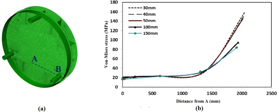
The external pressure was applied equally to 1atm on the external face of end cap (see Fig. 2) which is equal to the maximum practical relative pressure dif-ference between internal and external area of the duct. A 4-node doubly curved shell element called S4R was applied using reduced integration for all the simula-tions. Moreover, a comprehensive mesh convergence study was followed to reach an efficient element size. A typical study of convergence is shown in Fig. 3 across a path namely A-B shown in part (a). Fig. 3(b) illus-trates von Mises stress obtained through the path in-cluding different mesh sizes. The maximum mesh sizes were considered equal to 30, 40, 50, 100 and 150mm. It is crystal clear that models with elements finer than 50mm will end in similar results. Thus, in order to optimize calculation time, maximum size of end cap elements was eventually set at 50mm.
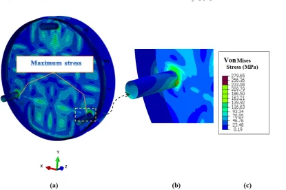
Fig. 4(a) illustrates the obtained von Mises stress in a simulated flat end cap whose h and t were 700 and 5mm, respectively. Fig. 4(b) shows a detailed view of the critical region. As can be seen, the maximum stress was approximately equal to 280MPa, which has occurred at the root of the two symmetric rods as a support pipe. The similar pattern was found in all ge-ometries. It seems to be a consequence of the external pressure that tends to bend the end cap inward and thus brings about the location of maximum stress in the bottom of the rods as principal obstacles against bending. It should be pointed out that, at the ulti-mate design, the maximum stress at the root of the rod was extremely reduced by means of sufficient
welded-triangular stiffeners.
Upon completion of all the simulations, the de-sired information was extracted and as is discussed in the next section, they were utilized to form favorable-objective equation.
4. Model Clarification
In order to investigate each parameter’s share on the induced stresses, a function oftandhwas fitted to the obtained data through simulations as;
σ
P =f(x, y) (1)
whereσis the maximum stress induced in the end cap,
P is the applied external pressure; f is a polynomial equation fitted to the obtained data through numeri-cal study;xandy are dimensionless forms ofhand t, respectively, and were defined as:
x= h
D
y= t
td
(2)
where D and td are diameter and thickness of main
duct, respectively, and f constituted a third-order equation formulated as Eq. (3):
f(x, y) = 3 ∑
j=0 3 ∑
i=0
αijxiyi i+j≤3 (3)
Table 2
Coefficients of Eq. (3).
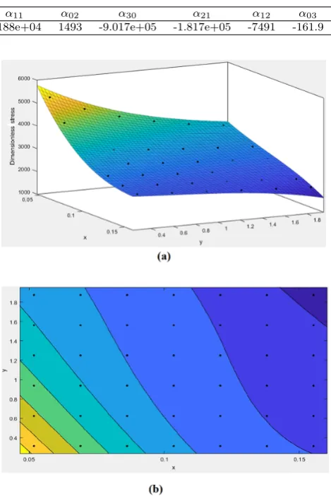
Coefficient α00 α10 α01 α20 α11 α02 α30 α21 α12 α03
Magnitude 1.124e+04 -1.288e+05 -5687 6.11e+05 6.188e+04 1493 -9.017e+05 -1.817e+05 -7491 -161.9
In Eq. (3) ,αij is a functional coefficient shown in
Table 2. This fitting has an R-squared item equal to 0.99 and residual average less than 1% that obviously shows how exact the fitted equation is. It is noteworthy that, based on the obtained residuals of fitted equations through a trial and error, 3rd-order polynomial equa-tion had the least error compared with lower degrees. An equation with higher order could be used as well. However, it causes a more elaborate equation with ap-proximately similar precision of 3rd-order equation.
It is also worth mentioning that, based on the
π Buckingham theorem [13], all the used parameters were made dimensionless to avert confronting probable problems in the dimensions of the two sides of equa-tions.
The contour of fitted surface to Eq. (1) is shown in Fig. 5(a). It is obvious that increasing h and t causes a reduction in stresses. A two-dimensional contour is also represented in Fig. 5(b) to provide more clari-fication. Regardless of the total end cap weight, the minimum stress is expected to appear at dusky zone (dark-violent region in right-up corner). Subsequently, for a constant weight, the most superior combination ofhandtwas obtained to attain the minimum stresses.
5. Optimization Model
In order to find an end cap with the least stresses in-duced on, the fitted function in previous section was employed. Furthermore, a relationship between weight andh andt was considered as a constraint to control the amount of material used in the structure. A linear precise function was defined as;
w=
1 ∑
i=1 1 ∑
i=0
pijxiyj (4)
where pij are functional coefficients detailed in Table
3 andwis dimensionless form of weight defined as;
w= mg
P t2
d
(5)
in which, m and g are the mass of flat end cap and gravitational acceleration (9.81m/s2), respectively.
Table 3
Coefficients of Eq. (4).
Coefficient p00 p10 p01
Magnitude 1.124e+04 -1.288e+05 -5687
Fig. 5. a) The contour of fitted surface, b) Two-dimensional contourxversusy.
Fig. 6. The acceptable region forxandygiven weight restriction.
Based on the desirable spring support to tolerate the weight of the designed-flat end cap, the maximum authorized mass was assumed equal to 16 tons. Allow-able weight is determined according to the maximum limitation of certain types of spring support consid-ered in the bottom of end cap to undergo weight loads. Therefore, according to Eq. (4), an added boundary condition was supposed as;
Fig. 6 shows all the considered boundary conditions to form an acceptable region. The inclined line deter-mines the restriction caused by the maximum weight.
6. Analytical Study
6.1. Kuhn-Tucker Conditions
In nonlinear optimization problems, the Karush-Kuhn-Tucker (KKT) conditions should be satisfied for a lo-cal minimum candidate [14]. The KKT procedure for non-linearization of equations is through generalization of Lagrange multipliers, which is able to solve prob-lems in the presence of inequality constraints. For in-stance, in order to minimizef(x)regardinggi(x)≤0
for i= 1,2,· · ·, m, as boundary conditions, the KKT conditions for X∗= [x∗1 x∗2 · · · x∗n] to be a local mini-mum are [14];
(a) ∂f
∂xi
+
m ∑
i=1
µj
∂g ∂xi
= 0 i= 1,2,· · · , n
(b)µigi= 0 j= 1,2,· · ·, m
(c)gi≤0 j= 1,2,· · ·, n
(d)µj ≥0 j= 1,2,· · ·, m
(7)
6.2. Solution
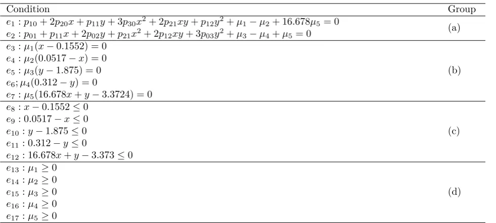
With regard to Eq. (3) in the current problem, the KKT conditions are listed in Table 4.
Based on these conditions, 14 different cases were considered, each of which was potentially a candidate of local minimum. The final results are also shown in Table 5 in a nutshell.
As can be observed in Table 5, the sole case that has satisfied all KKT conditions was case 3. In this case, the maximum stress obtained was equal to 236MPa. As can be seen in the next section, Genetic Algorithm (GA) has also confirmed this minimum stress point.
7. Genetic Algorithm
As a powerful technique, GA is able to get to the bottom of an optimization question even complicated problems, and also those ones that are difficult to ob-tain an exact solution analytically [15, 16]. A GA is a progressive algorithm based on natural evolution pro-cedure to find an optimum result through an able domain. A random “population” using accept-able region is made at first. Subsequently, over the next generation of the individuals, the algorithm tries to extract new members that are more appropriate in comparison with previous ones. Hence, each iteration procedure generally leads to the improvement of the an-swers, and it is expected that the best solution would be derived after the accomplishment of the algorithm [17].
“Crossover” and “mutation” are two frequent ways to create new generations. In crossover, a certain se-lection pressure is used to pick out two individuals as parents through former step. Merging genes of parents can breed new individuals as “offspring”. Note that using the sole crossover would lead to extracting local minimums.
In order to ensure certain exploration in the entire acceptable region, mutation was employed as another operator with less contribution. Note that excessive usage of mutation may prevent convergence [17].
Table 4
KKT conditions for current matter.
Condition Group
e1:p10+ 2p20x+p11y+ 3p30x2+ 2p21xy+p12y2+µ1−µ2+ 16.678µ5= 0 (a)
e2:p01+p11x+ 2p02y+p21x2+ 2p12xy+ 3p03y2+µ3−µ4+µ5= 0
e3:µ1(x−0.1552) = 0
(b)
e4:µ2(0.0517−x) = 0
e5:µ3(y−1.875) = 0
e6;µ4(0.312−y) = 0
e7:µ5(16.678x+y−3.3724) = 0
e8:x−0.1552≤0
(c)
e9: 0.0517−x≤0
e10:y−1.875≤0
e11: 0.312−y≤0
e12: 16.678x+y−3.373≤0
e13:µ1≥0
(d)
e14:µ2≥0
e15:µ3≥0
e16:µ4≥0
Table 5
Investigation of different cases to reach minimum candidate. Case
No. Assumptions Subsequent assumptions Results
Acceptable/ unacceptable 1 x= 0.1552y= 1.875 µ2=µ4=µ5= 0 e12: 1.091>0 unacceptable 2 x= 0.1552y= 0.312 µ2=µ3=µ5= 0 e2:µ4=−301<0 unacceptable
3 x= 0.1552 µ2=µ3=µ4= 0
e7:y= 0.784 acceptable
e1:µ1= 603.5
e2:µ5= 240.3
4 x= 0.1552 µ2=µ3=µ4=µ5= 0
e2:y= 0.272,3.48→ unacceptable Not in acceptable range
5 x= 0.0517, y= 1.875 µ1=µ4=µ5= 0 e1:µ2=−18390.7 unacceptable 6 x= 0.0517, y= 0.312 µ1=µ3=µ5= 0 e1:µ2=−60137.5<0 unacceptable
e2:µ4=−2330.78<0
7 x= 0.0517 µ1=µ3=µ4= 0
e12:y= 2.51 unacceptable
e1:µ2=−3833.5<0
e2:µ5= 482.76
8 x= 0.0517 µ1=µ3=µ4=µ5= 0
(8.1) ify= 1.658→ unacceptable
e1:µ2=−21998.6 (8.2) ify= 3.693→ Not in acceptable range
9 y= 1.875 µ1=µ2=µ4= 0
e12:x= 0.089 unacceptable
e1:µ5= 744.8
e2:µ3=−517<0
10 y= 1.875 µ1=µ2=µ4=µ5= 0 e1: No real answer forx unacceptable
11 y= 0.312 µ1=µ2=µ3= 0
e12:x= 0.1835 unacceptable Not in acceptable range
12 y= 0.312 µ1=µ2=µ3=µ5= 0
(12.1) ifx= 0.1697→ unacceptable Not in acceptable range
(12.2) ifx= 0.24→
e12= 0.94>0
13 µ1=µ2=µ3=µ4= 0 −
e12, e1 and e2 → x = 0.1661 or x = −1.4127 Not in acceptable range
unacceptable
14 µ1=µ2=µ3=µ4=µ5= 0 −
Obtainedxandy are not
in acceptable range unacceptable
In the present optimization,handt, in dimension-less form, were assumed as design variables. Variable acceptable ranges and variation domain oftandhwere considered as what is shown in Fig. 6. They were de-termined through optimization of Eq. (1). Acceptable region was also considered to be what is shown in Fig. 6. The final result was perfectly in compliance with those anticipated by analytical study.
8. Results
Given an extent for weight of end cap, a combina-tion of hand t has been obtained through analytical method and GA simultaneously. This was done using four other weight restrictions. These restrictions were assumed as 15, 15.5, 16.5 and 17 tons. The acceptable region and optimum point are represented in Fig. 7 in each case. Note that, in this figure, the
inclined-dash lines show boundaries created by limitations in weight. It can be observed clearly thath is more in-fluential thant in terms of reducing stress induced in the end cap. In other words, for a definite weight, the end cap with the largest h will be more appropriate than other possible cases. It can be justified through bending moments that are dominant type of normal stresses created by external pressure. These moments tend to bend the end cap inward. As can be seen in Fig. 4, maximum stresses have appeared at locations with maximum bending stresses. Based on the strength of material science, there is a conventional relationship
for bending stresses (
σ=M c
I
)
that confirms that a
growth atheffectively increases moment of inertia at a faster pace (the denominator of recent equation) and subsequently brings about a great reduction in bending stresses.
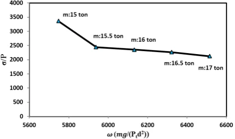
observed through different weight restrictions at opti-mal points. The results are accounted for in Fig. 8. As can be observed, the stresses have been plunged ex-ponentially approximately 27% from 15 to 15.5 tons. Subsequently, the changes up to 17 tons tend to reduce stress linearly at a rather slow rate. It means that using stronger material, typically with higher yield stress, is able to compensate for the lack of safety due to mass reduction. Note that this recommendation can be ap-plied only if possible and also affordable.
Fig. 7. Acceptable region and minimum stress point in 5 different weight restrictions.
Fig. 8. Maximum induced stress versus different weight restriction.
9. Discussion and Concluding Remarks
A general investigation of the reinforced end cap of an enormous pressure vessel under external pressure has been performed in this study. An array of constant-diameter flat end caps at different h and t were sim-ulated to observe the obtained trends. Subsequently, a function was fitted to the results to extract objec-tive function. Moreover, favorable boundary condi-tions were considered using a limitation for weight of the end cap. An analytical study and also GA were implemented to find an end cap that has the most economic and efficient design simultaneously. As was noted, for a certain weight, the end cap with the largest h was more appropriate than other possible cases. A comprehensive observation of the influence of the twogeometrical parameters was accomplished in different weight limits as well. It was found that although in-creasing the weight generally reduces stresses; there is a point beyond which the weight growth becomes less effective. Overall, this research proposes an exact pro-cedure to reduce the induced stresses under external pressure.
All in all, the findings in a nutshell are:
• Optimization of a huge duct under external pres-sure
• A rather extensive finite element study of blunt end caps
• Investigation of the impression of each geometri-cal factor
• A perfect compliance between analytical and GA method
10. Acknowledgement
Authors would like to thank Monenco Iran Consulting Engineers for its endorsement during the study. More-over, it is necessary to appreciate Mr. Amir Hossein Parand and Mr. Saeid Sepahi for their considerable as-sistance in improving the language of the manuscript.
References
[1] D.R. Moss, M. Basic, Pressure Vessels Design, Ox-ford, UK: Elsevier Inc., (2013).
[2] A.H. Mahmoudi, A.R. Hosseinzadeh, M. Jooya, Plasticity effect on residual stresses measurement using contour method, Int. J. Eng. 26(10) (2013) 1203-1212.
[3] A.T. Poojary, R.S. Sharma, M.H. Patel, D.U. Sheth, C.R. Kini, R. Nayak, Design and modelling of hemispherical and flat dish end pressure vessel, Indian J. Sci. Technol., 8(33) (2015) 1-7.
[4] G. Towler, R. Sinnott, Chemical Engineering De-sign: Principles, Practice and Economics of Plant and Process Design, Boston: Elsevier, (2013).
[5] S. Hassan, K. Kumar, Ch.D. Raj, K. Sridhar, De-sign and optimisation of pressure vessel using meta-heuristic approach, Appl. Mech. Mater., 465-466 (2014) 401-406.
[7] C.P. Fowler, A.C. Orifici, C.H. Wang, A review of toroidal composite pressure vessel optimization and damage tolerant design for high pressure gaseous fuel storage, Int. J. Hydrog. Energy, 41(47) (2016) 22067-22089.
[8] D. Leh, B. Magneville, P. Saffr, P. Francescato, R. Arrieux, S. Villalonga, Optimization of 700 bar type IV hydrogen pressure vessel considering com-posite damage and dome multi-sequencing, Int. J. Hydrog. Energy, 40(38) (2015) 13215-13230.
[9] A.E. Kumar, R.K. Santosh, S.R. Teja, E. Abishek, Static and dynamic analysis of pressure vessels with various, Materials Today: Proceedings, 5(2) (2018) 5039-5048.
[10] B.S. Kumar, P. Prasanna, J. Sushma, K.P. Srikanth, Stress analysis and design optimization of a pressure vessel using Ansys package, Materials Today: Proceedings, 5 (2018) 4551-4562.
[11] R.C. Carbonari, P.A. Muñoz-Rojas, E.Q. An-drade, G.H. Paulino, K. Nishimoto, E.C.N. Silva, Design of pressure vessels using shape optimization:
An integrated approach Carbonari, Int. J. Press. Vessels Pip., 88(5-7) (2011) 198-212.
[12] ABAQUS 6.14, User’s Manual, ABAQUS, (2014).
[13] E. Buckingham, On physically similar systems; illustrations of the use of dimensional equations, Phys. Rev., 4(4) (1914) 345-376.
[14] R.K. Arora, Optimization algorithms and ap-plications, Trivandrum, India: Chapman and Hall/CRC, (2015).
[15] A.R. Hosseinzadeh, A.H. Mahmoudi, Determina-tion of mechanical properties using sharp macro-indentation method and genetic algorithm, Mech. Mater., 114 (2017) 57-68.
[16] A.R. Hosseinzadeh, A.H. Mahmoudi, Measur-ing non-equi biaxial residual stresses and material properties using Knoop indentation, J. Test. Eval., 48(2) (In Press), DOI: 10.1520/JTE20170730.