1
WIDESENSE Project Report, V. 01/10/2015
WIDESENSE Project Report
Authors: Ms Helena Twigg, Dr Marc Molinari
Table of Contents
WIDESENSE Project Report ___________________________________________________ 1
Introduction ___________________________________________________________________ 2
The WIDESENSE Concept _________________________________________________________________ 2 Remit of this project _____________________________________________________________________ 2
The Microcontroller _____________________________________________________________ 2
The Lilypad Arduino _____________________________________________________________________ 2 Interfacing and Communication with the Lilypad Arduino _______________________________________ 3 Sensor Interfacing ______________________________________________________________________ 4
Transmission of Sensor Data ______________________________________________________ 5
Wireless Hardware ______________________________________________________________________ 5 Message Structure ______________________________________________________________________ 6
Storing of sensor data ___________________________________________________________ 8
The SD Card Shield ______________________________________________________________________ 8 Data Collected _________________________________________________________________________ 8
Suitability as a student project ____________________________________________________ 9
Future Work ___________________________________________________________________ 9
Appendices ___________________________________________________________________ 10
Arduino programs _____________________________________________________________________ 10 Comparison of data collected in different rooms of the house __________________________________ 18
Table of Figures
Figure 1: The Lilypad Arduino (Cool Components, 2015) _____________________________________________ 3 Figure 2: FTDI board showing ribbon cable and mini USB connection __________________________________ 3 Figure 3: Light sensor module KY 018 (www.nanotronik.pl, 2015) _____________________________________ 4 Figure 4: Temperature sensor module KY 013 (Arduino forums, 2015) _________________________________ 4 Figure 5: 433MHz transmitter (left) and receiver (right) (Squirrel Labs, 2015) ____________________________ 5 Figure 6: A received message shown on the receiving Mega's Serial Monitor ____________________________ 7 Figure 7: Light and Temperature data from RM711 overnight on July 21st 2015 _________________________ 8 Figure 8: Light and Temperature data from dining room on 7th August 2015 ___________________________ 18
2
WIDESENSE Project Report, V. 01/10/2015
Introduction
The WIDESENSE Concept
WIDESENSE - Wireless & Distributed Sensor Enhancement – was a research proposal put forward in summer 2014 by Dr Marc Molinari to the Southampton Solent University’s internal R&E bidding pro-cess. The original proposal was to create a wireless distributed sensor system at a low cost, such that many could be deployed in punitive environments where not all modules were expected to sur-vive. Because of the high numbers of modules deployed, enough data to produce significant results could still be obtained from the sensors contained therein.
Remit of this project
During this project, the objectives were narrowed to focus on the proof of concept. This meant that the following was investigated:
1) Interfacing of sensors to a miniature microcontroller board 2) Obtaining meaningful data from two or more sensors
3) Wireless transmission of sensor data from a miniature microcontroller board to a base sta-tion
4) Accurate reception of the data at the base station
Once the above four objectives had been met, enhancement of the sensor data could be investi-gated to make it more useful. This could include time- and date-stamping the data and marking it with a location (for example using a GPS).
The Microcontroller
It was decided, early in the life of the project, that the Arduino suite of microcontroller boards would be used. This was because they had already proved to be extremely useful to show students the concepts of embedded software and real-time sensor systems, so the researchers on this project knew that they could be used to rapidly prototype the WIDESENSE system.
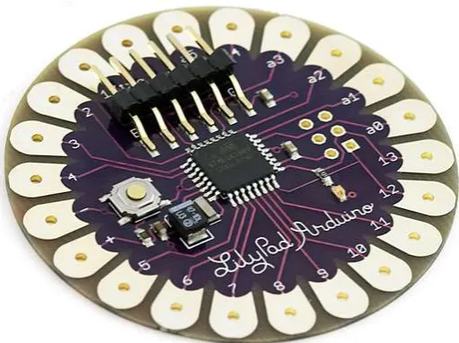
The Lilypad Arduino
3
WIDESENSE Project Report, V. 01/10/2015
example to control LEDs and have them react to the wearer’s movements. As a result it is small and light and has sufficient analogue and digital i/o for the proof-of-concept of WIDESENSE.
Interfacing and Communication with the Lilypad Arduino
In order to program the Lilypad Arduino, a separate TTL – UART interface module was needed. This
was obtained from eBay China and is known as an FTDI board after the original manufacturer. How-ever since its original design, many low-cost copies have been produced with design flaws. When the FTDI board was initially obtained, it was found that both the Lilypad and the FTDI board had male jumper headers and so they could not be connected together. They were joined by a female-female jumper lead but it was found that programming the Lilypad still was not possible. Eventually it was found that the FTDI board had a reversed pinout and having realised this, programming could begin in earnest.
The next problem that was encountered with the Lilypad was that the baud rate that was set in the Lilypad’s code needed to be monitored at double the rate on the serial monitor of the Arduino IDE. If the code contained the line:
Figure 1: The Lilypad Arduino (Cool Components, 2015)
4
WIDESENSE Project Report, V. 01/10/2015
Serial.begin(9600);
Then the serial monitor needed to be set to 19200 bps to read messages from the Lilypad.
Resolving problems with the Lilypad Arduino took about two weeks and it is recommended for un-dergraduate work that a Lilypad is not used. Instead, an Arduino MEGA or UNO should be used for the sensor module microcontroller board.
Sensor Interfacing
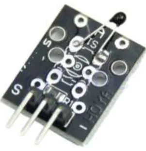
The sensors that were chosen for WIDESENSE proof-of-concept project were a light sensor and a temperature sensor. These data are commonly monitored remotely and as they are each found as discrete modules in the “37-in-1 Arduino Sensor Kit”, they were deemed to be the ideal starting point for data monitoring via the sensor module.
Figure 4: Temperature sensor module KY 013 (Arduino forums, 2015)
5
WIDESENSE Project Report, V. 01/10/2015
It was found that no documentation came with the 37-in-1 kit, and so information about the sensors and how to connect them was found onlineiii.
Both the light sensor and the temperature sensor contain analogue passive sensing components; the light sensor uses a photoresistor and the temperature sensor uses a thermistor. The values from these components are read by the Arduino as a digitised analogue value using the Arduino function analogRead().
The temperature sensor (module KY013) uses a Negative Temperature Coefficient thermistor (NTC), meaning that resistance of the thermistor decreases as temperature increases. Readings from the module were originally found to be erroneous until it was found that swapping the ground and posi-tive power supply leads gave accurate data. The sensor measured the temperature in RM711 as ap-proximately 27°C which was correct to within 0.5°C.
The light sensor (module KY018) outputs a value proportional to the light level incident on the pho-toresistor. In order for this value to be meaningful, some calibration tests would be needed to relate the value obtained to a known brightness.
Transmission of Sensor Data
Wireless Hardware
The next stage of the WIDESENSE project was to convert the sensing module into a transmitter of sensor data, and to create a receiver that could interpret and store the sensor data that had been transmitted. It was decided that the receiver microcontroller board would be an Arduino Mega, to ensure compatibility with the transmission side and also to be accessible to students.
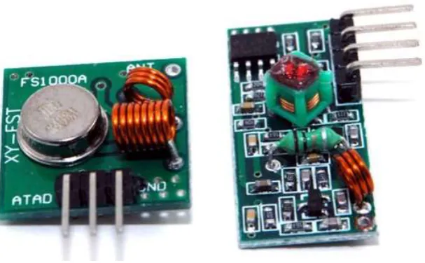
The smallest, lowest cost and most convenient transmitter and receiver option found was the 433MHz module seen below.
Figure 5: 433MHz transmitter (left) and receiver (right) (Squirrel Labs, 2015)
6
WIDESENSE Project Report, V. 01/10/2015
fobsiii. It was found during the course of this project that the transmitter effectively blocks the Toyota Verso wireless key fob at a distance of about ten metres.
It was found that there were no prewritten libraries for use with this module, and the user-written open source libraries, including VirtualWire.hiv, were not suitable for use with the Lilypad Arduino. As a result, the transmitter was used as a simple output, with the data pin set to high when trans-mission was required and low when it was not required.
It was then discovered by using a high frequency oscilloscope that when the transmit pin was set high, the module would transmit for approximately 168ms and would then go into an undefined state, switching quickly on and off repeatedly, before turning itself off after approximately 300ms. It is not currently known if this behaviour is intentional, and if so, the reason behind it. It is possibly there in order to provide a unique identifier for the receiver to tune to. In the timescale of this pro-ject however it was not feasible to investigate the purpose of this behaviour; it was necessary to work with the available components.
As a result, a modulation scheme was designed and written as a unipolar RZ code. A ‘1’ was sent as 20ms high followed by 10ms low, and a ‘0’ was sent as 10ms high followed by 20ms low. This en-sured that long periods of continuous transmission were avoided so that the transmitter would not “time out” as described above. The receiving end used the Arduino function pulseIn(), which returns an int equal to the length of time in milliseconds of the high pulse, to determine whether a ‘1’ or a ‘0’ was received.
Message Structure
It was determined that the message should have a structure that was scalable depending on the number of sensors whose data was to be transmitted. The message needed therefore to contain the following component parts:
1 message start,
2 a number to state how many sensors’ data were to be transmitted in the message
3 for each sensor:
a. a character to state what type of sensor’s data is about to be trans-mitted
b. the sensor’s data
4 message end once all the sensors’ data had been sent.
This structure was adopted because it enabled multiple sensors’ data to be sent in one message with fewer overheads.
Message Start
7
WIDESENSE Project Report, V. 01/10/2015
Number of Sensors
This was sent as an unsigned int, 16 bits long, so the maximum number of sensors’ data that can be sent in one message is 65535. This is overkill somewhat for the WIDESENSE project, so the Num-ber_Of_Sensors field could be encoded in a smaller type such as a char in future.
Sensor Type
This was sent as a char. As there were only two sensors attached to our transmitter, detecting tem-perature and light, the sensor type was encoded as ‘l’ for light or ‘t’ for temtem-perature. As above, this field could be sent more compactly as a char because it is envisaged that the maximum number of sensors on one module would be no greater than five.
Sensor Data
For both of the chosen sensors, the data value was requested from the sensor by using the Arduino function analogRead(). This function returns an int (16 bits); therefore, the value is transmitted in this form.
Message End
The message_end sequence is the reverse of the original message_start i.e. 1111111100000000b or 65280d.
Figure 6 below shows the message decoded in the Serial Monitor of the receiving Mega. Note that the letter ‘S’ is being used to monitor when a message_start is successfully decoded.
Figure 6: A received message shown on the receiving Mega's Serial Monitor
8
WIDESENSE Project Report, V. 01/10/2015
Storing of sensor data
The next stage of the WIDESENSE project was to actively collect data from the environment. In or-der to do so over an extended time period, a way of storing sensor data messages was needed. The best solution for this was to save messages to an SD (Secure Digital) card. This method of storage was chosen because it can hold many days’ worth of sensor data, it does not take up much space, it is inexpensive and there already exists hardware and software support to store data from an Ar-duino microcontroller onto an SD card.
The SD Card Shield
Many of the recent generation of affordable open-source microcontroller boards, such as the Rasp-berry Pi, BeagleBone and Arduino, have add-ons designed and made by enthusiasts worldwide. When the add-on contains hardware that is physically large, it is often contained in what is known as a “shield”. This is a specially designed circuit board containing the hardware, that fits onto the mi-crocontroller board, connecting into several of the i/o sockets on the board, usually more of them than the hardware needs to operate. The extra i/o pins then simply feed through onto the shield so that connections can be made into the shield and straight through onto the microcontroller board. The SD Card shield that was procured was also capable of providing a timestamp to the received sen-sor data by means of a real-time clock (RTC) integral to the circuit boardv. The RTC is provided by the Maxim DS1307 IC, which requires a coin battery to run and retain its settings when there is no power to the shield. It is vital, once the RTC has been initialised, to keep the coin battery connected, even if it runs flat.
Once the shield was installed, it was necessary to initialise the clock and start using it to timestamp data. The instructions found in reference (v) were followed and the SD.h library was included in the code to create a datafile to write values to. Unfortunately the instructions found in reference (v) did not work for the real-time clock and a different ds1307.h library was needed.
Data Collected
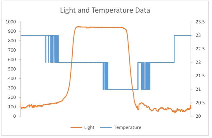
Data collected overnight in RM711 is shown below in graphical form:
Figure 7: Light and Temperature data from RM711 overnight on July 21st 2015
20 20.5 21 21.5 22 22.5 23 23.5
0 100 200 300 400 500 600 700 800 900 1000
Light and Temperature Data
9
WIDESENSE Project Report, V. 01/10/2015
It can be seen from Figure 7, which was taken from approximately 2:30pm on 21st July 2015 to ap-proximately 1:00pm on 22nd July 2015, that temperature drops overnight and returns to the same level at about the same time the next day; the temperature scale in °C is shown on the right. The uncalibrated light values rise overnight, which implies that the sensor + and – leads are swapped. However this setting has been kept for all data collection in order to provide a comparative view. Other data collected from different rooms in the author’s house during the month of August 2015 can be found in the appendix.
Suitability as a student project
It is considered that the work done in the WIDESENSE project would make an excellent basis for lab work in the level 6 module Radio Systems, starting in the academic year 2015-16. However some changes would have to be made to the setup described in this report as follows:
1) Do not use the LilyPad Arduino. Using this space saving microcontroller board caused sev-eral problems that are irrelevant to the learning outcomes of the Radio Systems module, such as the need to use the FTDI board, the confusing baud rate doubling between the code and the serial monitor. It is recommended that a Mega or Uno is used for the sensor inter-face and data transmission.
2) Use a computer to store data rather than the SD Card shield. If possible, write an app to write to a file on the computer via the serial link, or write to a file on the Mega, rather than trying to use the SD Card shield. This saves the expense of buying SD Card shields for every lab group. It is also not directly relevant to the Radio Systems module.
Future Work
A great deal more work is needed to make the system more robust and to take this project forward to becoming a marketable product.
1) Adding more sensing capability, such as noise, electricity and humidity monitoring. Also it would be useful to detect the difference between solar light and artificial light.
2) More investigation needs to be undertaken into the range capability of the 433MHz trans-mitter. It was found while monitoring light levels in the author’s home that in order to col-lect data reliably over a long time period (more than fifteen minutes), that the transmitter and receiver had to be right next to each other or the data dropout rate was so high that messages were decoded wrongly.
3) The receiver software was intolerant to partially received data messages and dropped bits. This is linked to the above issue but the receiver software needs also to be able to adapt when radio reception is less than ideal.
4) It was also found that if the receiving Mega was writing to the SD card, it would miss the start of messages sent from the LilyPad. In that circumstance, the entire message would be discarded and the data contained therein would be lost. This is linked to the Arduino oper-ating structure of looping, and the solution to this problem is unknown.
10
WIDESENSE Project Report, V. 01/10/2015
6) To create a truly wirelessly distributed sensor system, sensor modules must be able to municate reliably with each other in the event of one or more of them being unable to com-municate with a base station. Each module will also need to be able to store messages in the event of it being unable to communicate with the base station.
7) Multiple sensors must be able to communicate with one base station, so all data messages will need to identify themselves as originating from a particular module. The message struc-ture will have to be extended to add a module identifier.
8) Create a fully working system using discrete components rather than Arduino rapid proto-typing modules. Doing so would be a big step towards making a marketable product, and the Arduino-specific problems found during the project would no longer exist.
Appendices
Arduino programs
Data collation and message transmission on the LilyPad
Below is the code used on the LilyPad Arduino exactly as it was at the end of the WIDESENSE project. Debug code used in previous iterations has been left in but commented out.
#include <math.h>
#define rfTransmitPin 4 //RF Transmitter pin = digital pin 4 #define ledPin 13 //Onboard LED = digital pin 13
int thermosensorPin = A4; // select the input pin for the potentiometer int photoPin = A1;
void setup() {
pinMode(rfTransmitPin, OUTPUT); pinMode(ledPin, OUTPUT);
Serial.begin(9600);
pinMode(thermosensorPin, INPUT); pinMode(photoPin, INPUT);
}
void SendHIGH() {
//Serial.print("H");
digitalWrite(rfTransmitPin, HIGH); //Transmit a HIGH signal digitalWrite(ledPin, HIGH); //Turn the LED on
delay(40); //timings are weird because of the FTDI or lilypad or something, so actual value is half
digitalWrite(rfTransmitPin, LOW); //Transmit a LOW signal digitalWrite(ledPin, LOW); //Turn the LED off delay(20);
}
void SendLOW() {
//Serial.print("L");
digitalWrite(rfTransmitPin, HIGH); //Transmit a HIGH signal digitalWrite(ledPin, HIGH); //Turn the LED on
delay(20);
digitalWrite(rfTransmitPin, LOW); //Transmit a LOW signal digitalWrite(ledPin, LOW); //Turn the LED off delay(40);
}
void sendStart() {
11
WIDESENSE Project Report, V. 01/10/2015
digitalWrite(rfTransmitPin, HIGH); //Transmit a HIGH signal digitalWrite(ledPin, HIGH); //Turn the LED on
delay(80); //timings are weird because of the FTDI or lilypad or something, so actual value is half
digitalWrite(rfTransmitPin, LOW); //Transmit a LOW signal digitalWrite(ledPin, LOW); //Turn the LED off delay(20);
/*
for (int i = 0; i < 8; i++) {
SendLOW(); }
for (int i = 0; i < 8; i++) { SendHIGH(); } */ } void sendEnd() {
for (int i = 0; i < 8; i++) {
SendHIGH(); }
for (int i = 0; i < 8; i++) {
SendLOW(); }
}
void sendByte(char c) {
char t = c;
Serial.print("binary being sent: " ); for (int i = 0; i < 8; i++)
{
// send highest bit if (t & 128) { SendHIGH(); Serial.print("1"); } else { SendLOW(); Serial.print("0"); }
// shift right t = t << 1; }
Serial.println(); }
void sendValue(int v) {
Serial.print("VALUE being sent: " ); int a = v;
for (int i = 0; i < 16; i++) {
12
WIDESENSE Project Report, V. 01/10/2015
}
//shift right a = a << 1; }
Serial.println(); }
void sendSensor(char sensorID) {
char ch = sensorID;
for (int i = 0; i < 8; i++) {
if (ch & 128) { SendHIGH(); }
else {
SendLOW(); }
//shift right ch = ch << 1; }
}
int Thermistor(int RawADC) {
//Serial.print("Temp RawADC = "); //Serial.print(RawADC);
//Serial.print(" "); double Temp;
Temp = log(10000.0*((1024.0/RawADC-1)));
Temp = 1 / (0.001129148 + (0.000234125 + (0.0000000876741 * Temp * Temp ))* Temp );
Temp = Temp - 273.15; // Convert Kelvin to Celsius
//Temp = (Temp * 9.0)/ 5.0 + 32.0; // Convert Celsius to Fahrenheit return int(Temp) ;
}
void loop() {
int temp = Thermistor(analogRead(thermosensorPin)); int photo = analogRead(photoPin);
sendStart();
sendValue(2); //number of sensors sendByte('t'); //Sensor type
Serial.print("Temperature value is "); Serial.println(temp);
sendValue(temp); // temperature data sendByte('l'); //Sensor type
Serial.print("Light value is "); Serial.println(photo);
sendValue(photo); // light data sendEnd();
13
WIDESENSE Project Report, V. 01/10/2015
Reception and data storage on the Mega
Below is the code used on the Arduino Mega exactly as it was at the end of the WIDESENSE project. Debug code used in previous iterations has been left in but commented out.
/* Arduino wireless receive for an Arduino MEGA Written and designed by Helena Twigg
160715 */
#include <SPI.h> #include <SD.h> #include <DS1307.h>
#define rfReceivePin A0 //RF Receiver pin = A0
#define ledPin 13 //Onboard LED = digital pin 13
//variables to store received data
unsigned long HIGHDuration = 0; // length of received pulse
unsigned int receiveArray = 0; //Array in which to store received bits char sensorType;
unsigned int numberOfSensors = 0; unsigned int sensorsRemaining = 0; int sensorData;
static int receivedBits = 0; //counter of received bits File dataFile;
// make a string for assembling the data to log: String dataString = "";
//state flags
boolean messageStarted = false; boolean messageEnded = false; boolean sensorChosen = false; boolean dataReceived = false; boolean knowHowManySensors = false;
// RTC settings
// Init the DS1307 with:
// DS1307: SDA pin -> Arduino port 4 // SCL pin -> Arduino port 5 DS1307 rtc(4, 5);
void setup() {
pinMode(ledPin, OUTPUT); pinMode(rfReceivePin, INPUT); Serial.begin(19200);
if (!SD.begin(10, 11, 12, 13)) {
Serial.println("No SD Card, help..."); }
// Set up real time clock - RTC // Set the clock to run-mode rtc.halt(false);
// The following lines can be commented out to use the values already stored in the DS1307
//rtc.setDOW(FRIDAY); // Set Day-of-Week to SUNDAY
//rtc.setTime(14,42,00); // Set the time to 12:00:00 (24hr format) //rtc.setDate(17, 07, 2015); // Set the date to October 3th, 2010
// Open up the file we're going to log to and name it with a date dataFile = SD.open("sensors.csv", FILE_WRITE);
if (!dataFile) {
14
WIDESENSE Project Report, V. 01/10/2015
// Wait forever since we cant write data while (1) ;
}
//Start the data string that will eventually be our .csv file dataFile.println("Time, Temperature, Light");
}
void loop() {
HIGHDuration = pulseIn(rfReceivePin, HIGH); //returns length (in time) of pulse in microseconds, or 0 if it waits more than a second
boolean received = decodePulse(); //find out if it is a 1 or a 0 if (received)
{
checkState(); }
}
boolean decodePulse() {
if ((HIGHDuration > 5000) && (HIGHDuration < 15000)) //short pulse is a 0 {
receiveArray = receiveArray << 1; //shift array along one bit
bitWrite(receiveArray, 0 , 0); //wite a low bit to the lowest bit of the re-ceiveArray
receivedBits++; //increment receivedBits counter Serial.print("0");
return true; }
else if ((HIGHDuration > 15000) && (HIGHDuration < 25000)) //long pulse is a 1 {
receiveArray = receiveArray << 1; //shift array along one bit
bitWrite(receiveArray, 0, 1); //write a high bit to the lowest bit of the re-ceiveArray
receivedBits++; //increment receivedBits counter Serial.print("1");
return true; }
else if ((HIGHDuration > 25000)&&(HIGHDuration < 45000)) {
messageStarted = true; Serial.println("S");
dataString = String(rtc.getDateStr()) + " " + String(rtc.getTimeStr()) + ","; receivedBits = 0;
return true; }
Serial.print("X"); return false;
}
void checkState() {
if (receivedBits >= 16) {
if (messageStarted == false) {
//checkMessageStart(); return;
} }
15
WIDESENSE Project Report, V. 01/10/2015
{
if (knowHowManySensors == false) {
if (receivedBits == 16) {
//find out how many sensors' data are going to be in this message howManySensors();
Serial.print("Number of sensors in this message is "); Serial.println(numberOfSensors);
//dataString += String(numberOfSensors)+ ","; return; } } } if (sensorsRemaining) { if (!sensorChosen) {
if (receivedBits == 8) {
whichSensor(); return;
}
} else if (sensorChosen) //or just else, but clarity needed for now {
if (receivedBits == 16) {
sensorsRemaining--;
receiveByte(); //which is now two bytes sensorChosen = false; //for the next sensor return; } } } if (dataReceived) {
if (receivedBits == 16) { checkMessageEnd(); } } } /*void checkMessageStart() {
if (receiveArray == 255) //0000000011111111 sent as start of message {
messageStarted = true; //dataString = "";
dataString = String(rtc.getDateStr()) + " " + String(rtc.getTimeStr()) + ","; receivedBits = 0;
Serial.println("Message Started"); }
}*/
void checkMessageEnd() {
if (receiveArray == 65280) //1111111100000000 in binary, sent as end of message {
16
WIDESENSE Project Report, V. 01/10/2015
Serial.println("Message Ended");
dataFile.println(dataString);
// The following line will 'save' the file to the SD card after every // line of data - this will use more power and slow down how much data // you can read but it's safer!
// If you want to speed up the system, remove the call to flush() and it // will save the file only every 512 bytes - every time a sector on the // SD card is filled with data.
dataFile.flush();
Serial.print(dataString); Serial.println();
}
}
void whichSensor() {
// read the lower byte of the receive array sensorType = char(lowByte(receiveArray)); // For now, just print out what letter it is Serial.print("Sensor received is ");
//dataString += String(sensorType) + ","; switch (sensorType) {
case 'l':
Serial.print("light"); Serial.println(); break;
case 't':
Serial.print("temperature"); Serial.println();
break; default:
Serial.print("Sensor Type unknown: "); Serial.println(sensorType);
}
//set the flag for the next state sensorChosen = true;
//reset receivedBits receivedBits = 0; }
void howManySensors() {
// read the lower byte of the receive array numberOfSensors = receiveArray;
sensorsRemaining = numberOfSensors; //set the flag for the next state knowHowManySensors = true;
//reset receivedBits receivedBits = 0; }
void receiveByte() {
sensorData = receiveArray;
// Decide what to do with it based on the sensorType switch (sensorType) {
case 'l':
//do something useful with the light data
Serial.print("and the light data is equal to "); Serial.print(sensorData);
Serial.println();
17
WIDESENSE Project Report, V. 01/10/2015
break; case 't':
//do something meaningful with the temperature data Serial.print("and the temperature data is equal to "); Serial.print(sensorData);
Serial.println();
dataString += String(sensorData) + ","; break;
}
dataReceived = true; if (sensorsRemaining) {
sensorChosen = false; dataReceived = false; }
18
WIDESENSE Project Report, V. 01/10/2015
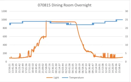
Comparison of data collected in different rooms of the house
Dining RoomFigure 8: Light and Temperature data from dining room on 7th August 2015
Conservatory
The data collected from the conservatory does not quite cover 24 hours. For the previous two days, data collection had been attempted but failed because of the extremes of temperature reached in the conservatory (>41°C to ~8°C). As a result the experiment was stopped early before the SD card failed as had happened on the previous two days.
0 5 10 15 20 25 30
0 200 400 600 800 1000 1200
12:56:21 13:45:28 14:34:35 15:23:42 16:12:49 17:01:56 17:51:03 18:40:10 19:30:45 20:19:55 21:09:02 21:58:09 22:47:16 23:36:23 00:25:30 01:14:37 02:03:44 02:52:51 03:41:58 04:31:05 05:20:12 06:09:19 06:58:26 07:47:33 08:36:40 09:25:47 10:14:54 11:04:01 11:53:08 12:42:15 13:31:22 14:20:29 15:09:36 15:58:43
070815 Dining Room Overnight
19
WIDESENSE Project Report, V. 01/10/2015
Figure 9: Light and Temperature data from conservatory on 9th August 2015
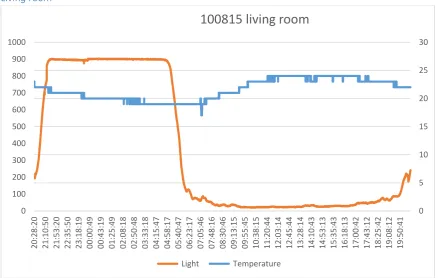
Living room
Figure 10: Light and Temperature data from living room on 10th August 2015
0 5 10 15 20 25 30
0 100 200 300 400 500 600 700 800 900 1000
20:32:27 21:11:02 21:49:36 22:28:11 23:06:45 23:45:20 00:23:54 01:02:28 01:41:03 02:19:37 02:58:12 03:36:46 04:15:21 04:53:55 05:32:29 06:11:04 06:49:38 07:28:13 08:06:47 08:45:21 09:23:56 10:02:30 10:41:04 11:19:39 11:58:13 12:36:48 13:15:22 13:53:56 14:32:31 15:11:05 15:49:40 16:28:14 17:06:48 17:45:23
Conservatory 090815
Light Temperature
0 5 10 15 20 25 30
0 100 200 300 400 500 600 700 800 900 1000
20:28:20 21:10:50 21:53:20 22:35:50 23:18:19 00:00:49 00:43:19 01:25:49 02:08:18 02:50:48 03:33:18 04:15:47 04:58:17 05:40:47 06:23:17 07:05:46 07:48:16 08:30:46 09:13:15 09:55:45 10:38:15 11:20:44 12:03:14 12:45:44 13:28:14 14:10:43 14:53:13 15:35:43 16:18:13 17:00:42 17:43:12 18:25:42 19:08:12 19:50:41
100815 living room
20
WIDESENSE Project Report, V. 01/10/2015
Hall
Figure 11: Light and Temperature data from hall on 13th August 2015
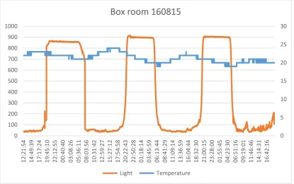
Box room
The data for the box room (small front bedroom) was collected over three nights.
Figure 12 : Light and Temperature data from box room on 16th-19th August 2015
19 19.5 20 20.5 21 21.5
0 100 200 300 400 500 600 700 800 900 1000
11:10:16 11:57:50 12:45:24 13:32:57 14:20:31 15:08:05 15:55:39 16:43:12 17:30:46 18:18:20 19:05:54 19:53:30 20:41:04 21:28:37 22:16:11 23:03:45 23:51:19 00:38:52 01:26:26 02:14:00 03:01:34 03:49:07 04:36:41 05:24:15 06:11:49 06:59:22 07:46:56 08:34:30 09:22:04 10:09:37 10:57:11 11:44:45
130815 Hall
Light Temperature
0 5 10 15 20 25 30
0 100 200 300 400 500 600 700 800 900 1000
12:21:54 14:49:39 17:17:24 19:45:10 22:12:55 00:40:40 03:08:26 05:36:11 08:03:56 10:31:42 12:59:27 15:27:12 17:54:58 20:22:43 22:50:28 01:18:14 03:45:59 06:13:44 08:41:29 11:09:14 13:36:59 16:04:44 18:32:30 21:00:15 23:28:00 01:55:45 04:23:30 06:51:16 09:19:01 11:46:46 14:14:31 16:42:16
Box room 160815
21
WIDESENSE Project Report, V. 01/10/2015
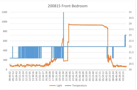
Front Bedroom
There is a discontinuity in the data between the times of 20:02:08 and 21:43:43 which can be seen in the graph.
Figure 13: Light and Temperature data from front bedroom on 20th August 2015
The collected data can also be found on the OneDrive at Solent at
https://ssu-my.share- point.com/personal/helena_twigg_solent_ac_uk/Documents/Research/WIDESENSE/Data%20col-lected
ihttps://tkkrlab.nl/wiki/Arduino_KY-013_Temperature_sensor_module, badly translated from Dutch, checked
6th August 2015
iihttp://forum.arduino.cc/index.php?topic=209133.0, checked 6th August 2015 iiihttps://en.wikipedia.org/wiki/LPD433, checked 20th August 2015
ivhttp://www.pjrc.com/teensy/td_libs_VirtualWire.html, checked 10th August 2015 vhttps://learn.adafruit.com/adafruit-data-logger-shield, checked 10th August 2015
20 20.5 21 21.5 22 22.5 23 23.5 24 24.5 25
0 200 400 600 800 1000 1200
08:46:02 09:27:53 10:09:43 10:51:34 11:33:24 12:15:15 12:57:05 13:38:56 14:20:46 15:02:37 15:44:27 16:26:18 17:08:08 17:49:59 18:31:49 19:13:40 19:55:30 22:18:56 23:00:46 23:42:37 00:24:28 01:06:18 01:48:09 02:29:59 03:11:50 03:53:40 04:35:31 05:17:21 05:59:12 06:41:03 07:22:53 08:04:44 08:46:34 09:28:25 10:10:15