Volume 4, Issue 2, 2017
53 Available online at www.ijiere.com
International Journal of Innovative and Emerging
Research in Engineering
e-ISSN: 2394 - 3343 p-ISSN: 2394 - 5494
Virtual Telepresence Robot
Shamin P Shaji, Sharon Mariam George, Rahul Shaji, Steffy Don, Ms P Careena
Amal Jyothi College of Engineering, Kanjirappally, Kottayam, Kerala, India
ABSTRACT:
A telepresence robot is a remote-controlled, wheeled device with a display to enable video streaming which enable the participants to view remote locations, as if they were there. The project consist of a VR headset, with a smartphone in dual screen to experience virtual reality and 4 wheeled robotic vehicle. The movement of the Robot is controlled using a remote controller. The motion of the camera of the robot is controlled by the accelerometer and magnetometer data processed by Arduino and Raspberry Pi. Video streamed is received by the smartphone using the IP address specified by the Raspberry Pi.
Keywords: Remote-controlled, Video streaming, VR headset, Raspberry Pi, Arduino
I. INTRODUCTION
From time immemorial, people faced a lot of limitations without technology. But now as time has passed, people are unable to live without technology. The evolution of mechanical computers to portable tablets and mobile phone has advanced the human race to a next higher level. The world we live in now is one that provides the required entity at just one click. It is also to be noted that the development in science and technology has introduced the concept of virtual reality and robotics. The term virtual means near and reality is what we experience as human beings. Hence ‘virtual reality’ means ‘near reality’. Robots have increased widely in today’s world. In almost all the industries the concept of robotics is used. Robots are also user friendly. Like all real world applications robots has its own disadvantages. Robot needs a supply of power. The robot used in this project uses rechargeable battery. Telepresence
is the use of virtual reality technology, especially for remote control of machinery or for apparent participation in
distant events. Virtual telepresence robot allows the user to experience virtual reality even when the robot is in a remote location.
The idea behind this project is taken from ref. paper [1]. This paper explains the working of the robot and capturing of the visuals. Ref. paper [2] talks about Raspberry Pi and its architecture including both hardware and software. The ref. paper [3] gives us a highlight of connecting and controlling motors to the Raspberry Pi. Ref paper [4] talks about Automatic Photography and the communication between the camera module and Raspberry Pi. Ref. paper [5] tells about robotic arm controlled by Raspberry Pi and android application software using Wi-Fi protocol. It also tells about how to configure Wi-Fi and interfacing servo motors with Raspberry Pi. It explains about how to send data from android application to Raspberry Pi.
In the case of Ref. paper [1] the mini rover camera is stationary. As the rover moves the camera moves along. Here the visual received is the one that is directly in front of it. In the proposed system we have the facility to rotate the camera according to our head movement. The mini rover gives a normal display. Whereas in the proposed system we get a virtual reality effect.
II. PROPOSED SYSTEM
Volume 4, Issue 2, 2017
54 Figure 1. Block Diagram
B. Description
The project is framed as shown in the block diagram. The Raspberry Pi is the brain of the system. It receives input from the smartphone via Wi-Fi and sent the output to be viewed in the same way. The Raspberry Pi gives input to the servo motors to turn it. The Raspberry Pi gives input to the Arduino Mega for the purpose of navigation. The motor driver and geared motors are connected at the end of the navigation circuit. ASK demodulation takes place at the RF module. The data is decoded. The commands to run the robot is given via Bluetooth or the RF module. C. Hardware
The hardware used in the project are affordable and easy to find both online and in the local market. Every part of the project was made from scratch. Given below is the short description and list of the various hardware used in the project:
Raspberry Pi 3 model B
The choice of Raspberry pi is because it allows easy video transmission over Wi-Fi. The Raspberry pi is considered as the CPU of the robot. The Raspberry Pi 3 Model B is the third generation Raspberry Pi. This powerful credit-card sized single board computer can be used for many applications.
Figure 2. Raspberry Pi 3
The Reason for selecting Raspberry pi as the main processing board is due to the facts that are mentioned below:
o The Raspberry pi requires very less power. It can be powered up by simply connecting to a 5V power bank. o The cost is low compared to other processing boards(USD 35)
o The OS that runs the Raspberry pi is the Raspbian OS which is open source. It has a Micro SD slot for storing information and loading the operating systems.
o It has a 40pin extended GPIO to enhance your “real world” projects.
L239D Motor Driver IC
The L293D allows the DC motor to drive in either direction. L293D is a 16-pin IC which can control two DC motors simultaneously. The gear motors are turned in the direction specified by the Arduino. It is seen that the power from the Arduino is insufficient to Drive the gears hence we use the motor driver IC.
H12 Encoder and Decoder IC
The HT 12E Encoder ICs are capable of Encoding 12 bit of information which consists of N address bits and 12-N data bits. Each address/data input is externally trinary programmable if bonded out. The HT 12D Decoder ICs are used in remote control system applications. These ICs are paired with each other. For perfect operation a pair of encoder/decoder with the same number of address and data format should be selected.
Camera
To capture video footage we use a camera. It's able to capture clear 5MP resolution image, or 1080p HD video recording at 30fps. A fisheye lens is kept in front of the camera in order to provide a 3D visual of the area.
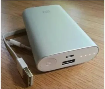
Power Bank
Volume 4, Issue 2, 2017
55 Figure 3. Power bank
VR Headset
A VR headset allows the user to experience virtual reality through visuals.
Figure 4. VR headset
Arduino Mega
The Arduino board acts as the directional processor of the robot. The commands to drive the robot in the specified direction is processed and given by the Arduino to a driver IC which in turn causes the motors to run.
Figure 5. Arduino Mega
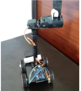
Casing of the robot
To build up the structure of the robot a metallic casing was welded with a pole onto which another casing was attached to hold the camera and Raspberry Pi. The wheels were fixed at the edges. The power supply board, the navigation circuit is placed beneath the casing. The Arduino is place above the casing. In the second casing at the top the Raspberry Pi is placed above which the camera module is stuck using a glue-gun.
D. Software
The main programming languages and software used are listed:
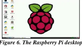
Raspbian OS
The Raspbian OS is flashed on to a memory card of 32GB. This is then inserted in the memory card slot of the Raspberry Pi board. The power bank is connected to the board to supply power to turn it on. The Raspberry Pi kernel can be accessed by typing in the username and password in the remote desktop.
Figure 6. The Raspberry Pi desktop
Python
In this project, Python is the best programming language that can be used in Raspberry Pi to interact with user.
PHP
This hypertext pre-processor is used in the setting up the website where in the video captured is displayed.
Arduino IDE
The C/C++ language is used to program the Arduino.
III. FEATURES The features of the project are:
The robot should be able to move forward, backward, left and right on its four wheels with the components on board by receiving commands from the remote controller.
The camera is a 5MP image resolution module to capture clear, real time visuals of the area in front. The camera moves in the same direction as the VR headset.
Video stream data from the camera should be sent to the Raspberry Pi over the Wi-Fi for being displayed to the user’s screen.
IV. PROJECT SETUP
The 1st stage of project hardware is the power supply. Rechargeable batteries are used in the power supply in
Volume 4, Issue 2, 2017
56 Arduino and then provided to the driver IC which drives the gear motor in the required direction. This operation can be controlled by transfer of data through Wi-Fi or Bluetooth or RF modules as transmitter and receiver. The casing to hold the gear motors, servo motors, camera and Raspberry Pi was made intact.
The next main procedure is the setting up of the Raspberry Pi. The initial configurations are done. The board is connected to the Wi-Fi. An IP address is programmed and setup which links to the Raspberry Pi. The video that is captured by the camera is sent over to the Wi-Fi modem. The modem creates a LAN where in both the smartphone and the Raspberry Pi are connected. It is through this LAN that the data (head movement and video) is shared. This transmitted output can be viewed by connecting the smartphone or the laptop to the same Wi-Fi connection and IP address. This transmitted output is viewed in a smartphone placed in the VR headset. The smartphone is switched to dual screen mode for this purpose.
The project also has the feature of letting the user experience virtual reality by swinging the VR headset. The smartphone reads the accelerometer and magnetometer data of the direction in which the user had turned. This data is sent to the modem over Wi-Fi and to the Raspberry Pi board which in turn provides these values as input to the servo motor. There are two servo motors which are used to move the camera. One for the vertical and other for the horizontal movement.
V. RESULT AND DISCUSSION
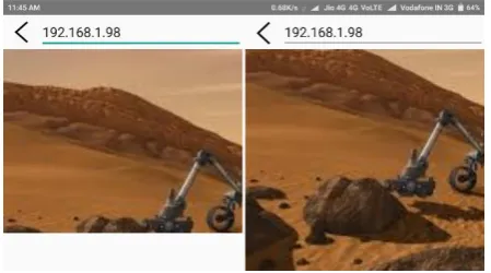
After assembling the hardware properly and installing & running the software, we successfully demonstrated that the telepresence robot can provide us with a 1080p color video of the area in the direction of our requirement.
Figure 7. IMU wireless app screenshot
Volume 4, Issue 2, 2017
57 Figure 9. Dual screen mode screenshot
VI. CONCLUSION AND FUTURE SCOPES
A. Limitations and solutions:
In order for video transmission to happen a Wi-Fi connection is required. Over a LAN the transmission is almost instantaneous but it keeps varying over slower Wi-Fi. High speed internet connectivity can solve this problem.
The directional data are transferred as the head moves. In the case when the head moves very fast the data transfer rate is high. This in turn requires the Raspberry Pi to process the data very quickly. The app should be programmed in such a way that the Raspberry Pi board gets enough time to process the data and prove it as input to the servos.
The currently designed robot is suitable to run over smooth surfaces. Stronger body of the robot allows it to run over rougher terrains.
B. Application
This robot can be used as a surveillance robot. In situations where the house owner needs to keep an eye of what the servant is up to at home. Other applications include:
In the case of military, instead of sending a soldier to a sight for monitoring the robot can be sent. In this way, even if there is an unexpected attack no life is lost only the robot is under damage.
In the Medical case, at times when the doctor is not able to go on rounds, the robot can be used to check the state of the patient.
If the robot is made fire proof, then the robot can be used in fire and rescue operations.
On further expansion of the robot and increasing its connectivity, the robot can be used in space research.
REFERENCES
[1] Nazmul Hossain, Mohammad Tanzir Kabir, “A Real-time Surveillance Mini-rover Based on OpenCV-Python-JAVA Using Raspberry Pi 2”, 2015 IEEE International Conference on Control System, Computing and Engineering, 27 - 29 November 2015, Penang, Malaysia.
[2] P. Jamieson, “Arduino for teaching embedded systems. are computer scientists and engineering educators missing the boat?” in Proc. FECS, pp. 289–294, 2010.
[3] Ana Marie. D Celebre, Ian Benedict A. Medina, “Home Automation Using Raspberry Pi through SiriEnabled Mobile Devices”, 8th IEEE International Conference Humanoid, Nanotechnology, Information Technology Communication and Control, Environment and Management 9-12 December 2015, Waterfront Hotel, Cebu City, Philippines.
[4] Zsolt Szécsi, Károly Simon, “Argus: Hardware and Software System for Automatic or Semi-automatic Photo Taking”, SISY 2015 IEEE 13th International Symposium on Intelligent Systems and Informatics September 17– 19, 2015, Subotica, Serbia.