http://www.sciencepublishinggroup.com/j/ajece doi: 10.11648/j.ajece.20170102.13
Impact of Various Signal Detection Schemes in
Performance Assessment of 5G Compatible LDPC Encoded
GPQSM Wireless Communication System
Md Tahin Hossain
1, Indraneel Misra
2, Joarder Jafor Sadique
3, Shaikh Enayet Ullah
41
Department of Electrical and Electronic Engineering (EEE), Prime University, Dhaka, Bangladesh
2
Department of Computer Science and Engineering, Khwaja Yunus Ali University, Sirajgong, Bangladesh
3
Department of Electronics and Telecommunication Engineering (ETE) Begum Rokeya University, Rangpur, Bangladesh
4
Department of Applied Physics and Electronic Engineering (APEE), University of Rajshahi, Rajshahi, Bangladesh
Email address:
To cite this article:
Md. Tahin Hossain, Indraneel Misra, Joarder Jafor Sadique, Shaikh Enayet Ullah. Impact of Various Signal Detection Schemes in
Performance Assessment of 5G Compatible LDPC Encoded GPQSM Wireless Communication System. American Journal of Electrical and Computer Engineering. Vol. 1, No. 2, 2017, pp. 72-80. doi: 10.11648/j.ajece.20170102.13
Received: April 9, 2017; Accepted: April 18, 2017; Published: June 8, 2017
Abstract:
In this paper, an effort has been made to assess critically the performance of 5G Compatible LDPC encoded generalized pre-coding aided quadrature spatial modulation (GPQSM) scheme based wireless communication system. With adaptation of ZF pre-coding at the transmitter side under the utilization of 4-QAM digital modulation, data transmission is made through 4 ×6 multi antenna supported MIMO GPQSM system. The system incorporates Minimum mean square error (MMSE), Zero-Forcing (ZF), Zero-Forcing-Successive interference cancellation (ZF-SIC) and optimal Maximum-Likelihood (ML) signal detection schemes. Various LDPC iterative channel decoding algorithms such as Log Domain Sum-Product, Simplified Log-Domain Sum Product and Probability-Domain Sum Product have been used. It is observable from MATLAB based simulations that the LDPC encoded GPQSM system shows quite satisfactory performance under scenario of MMSE signal detection scheme.Keywords: Index Modulation, GPQSM, LDPC Channel Coding, ZF, MMSE. ZF-SIC Signal Detectors, Bit Error Rate
1. Introduction
In our modern society, a general trend of increasing video based data traffic in cellular networks is being observed due to explosive demand for high quality video through sharing with social media such as YouTube and ultra HD (UHD) and 3D video from mobile devices (e.g., android tablets, smart-phones etc). The global data traffic will increase by more than 200 times from 2010 to 2020andabout 20,000 times from 2010 to 2030. The fifth-generation (5G) mobile communications system will emerge to meet up new and unprecedented demands beyond the capability of previous generations of systems. The peak data rate in 5G will be 20 Gbps with energy efficiency100 times and spectrum efficiency 3–5 times as compared to IMT-Advanced [1]. With unprecedented levels of spectrum and energy efficiency,
energy-efficient 5G wireless communications systems In 2017, Beixiong Zheng and et.al., proposed two types of low-complexity detectors based on the sequential Monte Carlo (SMC) theory for the detection of MIMO-OFDM-IM signals[3].Index modulation is an emerging signal modulation concept. Such scheme modulates signals through the indices of some medium, which can be either practical, such as antenna, frequency carrier, and subcarrier, or virtual, such as timeslot, space-time matrix, and antenna activation order. The indices are embedded into the transmitted or received signals, usually consuming little or even no power but carrying additional information. Recently, spatial modulation (SM) [4], which activates a single transmit antenna for transmission, has been proposed. Inspired by SM, many follow-up works have been proposed. Spatial modulation (SM) is widely acknowledged to be the pioneer that realizes the concept of index modulation. The generalized pre-coding aided quadrature spatial modulation (GPQSM) scheme extends SM to the receiver side. In GPQSM Index modulation works on both the in-phase and quadrature parts of the received signals [5]. The present study is giving emphasis on the effectiveness of various signal detection schemes in performance assessment of 5G compatible GPQSM system.
2. LDPC Channel Coding and Decoding
In this section, a brief overview of the LDPC (Low density parity-check) channel coding and decoding schemes has been given. LDPC codes were invented by Robert Gallager [6] in his PhD thesis. In LDPC channel coding, an Irregular Gallagher (IG) parity-check sparse matrix [H] of dimension of 64×128 is used with a transmitted binary valued code word u=[u1, u2, u3,…………. u128]. The message bits, s=[s1,
s2, s3,…………. s64] are located at the end of this code word
u and the parity check bits, c=[ c1, c2, c3,…………. c64]
occupy the beginning of the code word, viz. u=[c|s] The parity-check matrix [H] is formed from a concatenation of two matrices [A] and [ B] ([H]=[A]|[B]), each has a dimension of 64×64. The matrix [A] is an identity matrix.
The 1 × 128 sized code word vector u is consideredin such a way that
[u][H]T=0 (1)
The parity check bits vector c is computed using the following relation [7]
[c]=[A]-1[B][s] (2)
In LDPC channel decoding, various iterative approaches are adopted based on Tanner graph. The graph has two types of nodes: bit nodes and parity nodes. Each bit node represents a code symbol and each parity node represents a parity equation. The decoder operates alternatively on the bit nodes and the check (parity) nodes to find the most likely code word. In this paper, three iterative LDPC decoding algorithms such as Log Domain Sum-Product, Simplified log-domain sum product and Probability-domain sum product have been implemented with available MATLAB source codes at [8]
3. Signal and System Models
Prior to give a brief description of our 5G Compatible LDPC encoded GPQSM wireless communication system, a conceptual structural feature of GPQSM transceiver has been presented in Figure 1.
Figure 1. Structural feature of GPQSM transceiver [5].
In such transceiver, 4-QAM digital modulation (M=4) is used with the number of transmitting antennas (Nt) and the
number of receiving antennas ((Nr) are of six and four
transmitted. The first four consecutive bits are treated as signal bits to produce Np(=2) number of digitally modulated
symbols. The next two bits are treated as spatial bits used to select an antenna combination for transmitting in-phase (real) parts (xI) of the digitally modulated symbols. The last two bits are also treated as spatial bits used to select an antenna combination for transmitting quadrature (imaginary) parts (xQ) of the digitally modulated symbols. The GPQSM signal vector x is ZF precoded with P and further multiplied with a diagonal matrix estimated from P to produce transmitted signal vector X as:
X = PDx = PD(xI + jxQ) (3)
Where, P C∈ 6 4× =HH(HHH) ,−1 H∈C4 6× is the complex channel matrix and its each element is normalized in such a way that power gain of its each element is unity and the Frobenius norm of the matrix H,
D is the 4×4 diagonal matrix whose η-th diagonal elements
2
( ) 1 /
dη = Pη with Pη denoting η-th column of P.
The received signal vector y∈ CNr×1 can be expressed as
y = HPDx + w (4)
where, w ∈ CNr×1 is an AWGN vector with zero mean and noise variance ơn
2
. The GPQSM signal vector
xˆ
is detected using optimal ML detector as:min
min , (5)
Where, xref is the 4×1 sized GPQSM reference signal. It
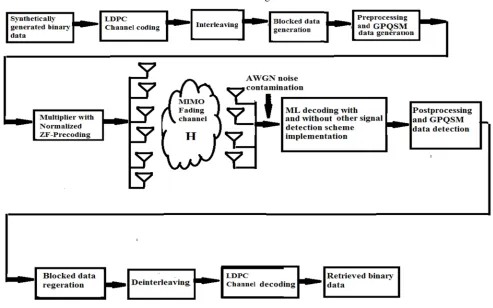
has 256 combinations as the number of binary (0/1) bits in one processing block is 8. The reasonably accepted GPQSM reference signal is further processed with the adaptation of index modulation scheme for detection of a block containing desired eight binary information bits. Our developed MATLAB source code presented in the Appendix provides a conceptual idea for processing a single blocked information data presented in Figure 1 and their retrieval under implementation of index modulation scheme. Our presently considered simulated 5G Compatible LDPC encoded GPQSM wireless communication system is depicted in Figure 2.
Figure 2. Block diagram of 5G Compatible LDPC encoded GPQSM Wireless Communication System.
In such simulated system, performance will be keenly observed merely for synthetically generated binary data. The binary signal vector S∈
( )
0,1 of dimension 1× 8192 is channel encoded using LDPC and subsequently interleaved to produce a signal vector sɶ . The 1 × 16384 sized transformed signal vectorsSɶ is rearranged into 2048 blockstransmitted signal vector (PDx) is of 6× 2048 sized. On transmission through MIMO fading channel H, the received signal y(=HPDx) is in dimension of 2× 2048. On noise contamination, it takes the form shown in Equation 2. Equation 3 makes its suitability for merely ML detection algorithm implementation.
For additional signal detection scheme are implemented, Equation (4) can be written as:
y=Hxɶ +w (6)
where, Hɶ
(
=HPD)
is the equivalent channel. In Zero-Forcing (ZF) based QPQSM signal detection scheme, the ZF weight matrix is given by1
( H ) H
ZF
W = H Hɶ ɶ − Hɶ (7)
and the detected desired QPQSM signal from the transmitting antenna is given by
ZF ZF
xɶ =W y (8)
In Minimum Mean Square Error (MMSE) based GPQSM signal detection scheme. The MMSE weighted matrix is given below
2 1
( H ) H
MMSE n
W = H Hɶ ɶ +σ I − Hɶ
and the detected desired GPQSM signal from the transmitting antenna is given by [9]
MMSE MMSE
Xɶ =W y (9)
In ZF-SIC based GPQSM signal detection scheme, the transmitted GPQSM signal x is detected from the received signal y. The equivalent channel matrix Hɶ undergoes QR factorization as
1,1 1,2 1,3 1,4
2,2 2,3 2,4
3,3 3,4
4,4 0
0 0
0 0 0
R R R R
R R R
H QR Q
R R R = = ɶ
Equation (3) is multiplied with QT to provide a modified form of received signal as [10]:
(
)
( )
T T T T
yɶ=Q y=Q Hxɶ +w =Q QRx+w =Rx+Q w (10)
In Equation (8), QTw is denoted by w as the statistical properties of both components are identical. Neglecting noise component and assuming a single time slot, the transmitted four
Components, x x x and xɶ ɶ ɶ1, 2, 3 ɶ4 of GPQSM signal vector can be estimated from solving the following equation
1,1 1,2 1,3 1,4
1 1
2,2 2,3 2,4
2 2
3 3,3 3,4 3
4 4,4 4
0
0 0
0 0 0
R R R R
y x
R R R
y x
y
y R R x
y R x
= = ɶ ɶ ɶ ɶ ɶ ɶ ɶ ɶ ɶ (11) 1 , 1 4 4 , 1 3 3 , 1 2 2 , 1 1 1 2 , 2 4 4 , 2 3 3 , 2 2 2 3 , 3 4 4 , 3 3 3 4 , 4 4 4 R ) x ~ R x ~ R x ~ R y ~ ( x ~ and R ) x ~ R x ~ R y ~ ( x ~ ; R ) x ~ R y ~ ( x ~ ; R y ~ x ~ − − − = − − = − = = (12)
The detected GPQSM signal is further processed for detection of block wise information bits, rearrangement of binary data in 1× 16384 form, LDPC channel decoded and retrieval of transmitted binary data in 1× 8192 form.
4. Results and Discussion
We have conducted computer simulation study using MATLAB R2014ato evaluate the performance of 5G
Compatible LDPC encoded GPQSM Wireless
Communication System based on the parameters presented in Table 1 It is assumed that the channel state information (CSI) of the MIMO fading channel is available at the receiver and the fading process is approximately constant during the whole period of signal transmission.
Table1. Summary of simulation model parameters.
Parameters Types
Data type: synthetically generated binary data 8192
Antenna configuration 6(Transmitting) × 4(Receiving)
Digital modulation 4-QAM
Channel coding LDPC
LDPC decoding Algorithm Log Domain Sum-Product, Simplified log-domain sum product and Probability-domain sum product
No of iterations in LDPC decoding 10
SNR 0-10 dB
Signal detection techniques used Optimal ML, Zero Forcing(ZF), MMSE and MMSE-SIC
On critical observation of graphical illustrations presented in Figure 3 through Figure 6, it is found that the performance of the LDPC encoded simulated system is very much well defined under the considered simulation parameters.
Figure 3. BER performance comparison of 5G Compatible LDPC channel encoded GPQSM Wireless Communication System with implementation of various LDPC decoding algorithms, linear Zero-forcing (ZF) pre-coding and optimal ML signal detection schemes.
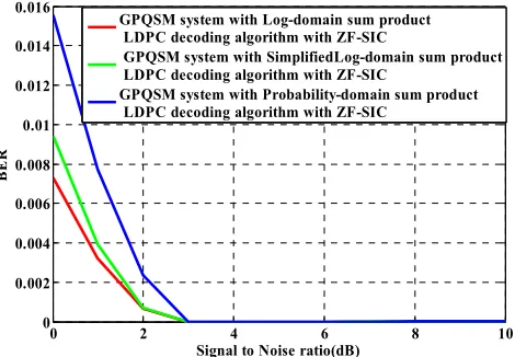
Figure 4. BER performance comparison of 5G Compatible LDPC channel encoded GPQSM Wireless Communication System with the implementation of various LDPC decoding algorithms, linear Zero-forcing (ZF) pre-coding and ZF-SIC signal detection schemes.
In Figure 3, it is quite observable that the LDPC encoded simulated system under utilization of various LDPC decoding algorithms, linear Zero-forcing (ZF) pre-coding and optimal ML signal detection schemes shows comparatively better performance with implementation of Probability-domain sum product decoding algorithm as compared to Log Domain Sum-Product and Simplified log-domain sum product decoding algorithms over a comparatively low SNR value region(0dB-5dB). For a typically assumed SNR value of 1dB, the estimated BER values are 0.2792, 0.2950 and 0.2993 in case of Probability-domain sum product, Log Domain Sum-Product and Simplified log-domain sum
product which is indicative a system performance improvement of 0.301913dB and 0.239066dB in Probability-domain sum product as compared to Simplified log-Probability-domain sum product and Log Domain Sum-Product. It is quite obvious from Figure 4, the impact of ZF-SIC signal detection scheme in performance assessment of LDPC encoded GPQSM wireless communication is quite mentionable. Under the scenario of identical signal and noise power at 0dB SNR value.
The estimated BER values are 0.0073, 0.0094 and 0.0156 in case of Log Domain Sum-Product, Simplified log-domain sum product and Probability-domain sum product which is indicative a system performance improvement of 3.298017 dB and 2.199967 dB respectively in Log Domain Sum-Product as compared to Simplified log-domain sum product and Probability-domain sum product. At 4% BER, SNR improvement of 1.0dB and 0.3dB in Log Domain Sum-Product as compared to Probability-domain sum product and Simplified log-domain sum product. The BER values approach zero at merely 3dB SNR values for every cases of LDPC decoding algorithm implementation.
Figure 5. BER performance comparison of 5G Compatible LDPC channel encoded GPQSM Wireless Communication System with implementation of various LDPC decoding algorithms, linear Zero-forcing (ZF) pre-coding and MMSE signal detection schemes.
In Figure 5, it is quite noticeable that the presently considered LDPC encoded simulated system under utilization of various LDPC decoding algorithms and implementation of MMSE signal detection scheme shows comparatively better performance in implementation of Log Domain Sum-Product as compared to Probability-domain sum product and Simplified log-domain sum product. The estimated BER values are 0.0006, 0.0017 and 0.0029 in case of Log Domain
Sum-Product, Probability-domain sum product and
Simplified log-domain sum product which is indicative a system performance improvement of 6.842467 dB and 4.522977 dB in Log Domain Sum-Product as compared to Simplified log-domain sum product and Probability-domain sum product respectively.
0 2 4 6 8 10
0 0.05 0.1 0.15 0.2 0.25 0.3 0.35
Signal to Noise ratio(dB)
B
E
R
GPQSM system with Log-domain sum product LDPC decoding algorithm GPQSM system with SimplifiedLog-domain sum product LDPC decoding algorithm GPQSM system with Probability-domain sum product LDPC decoding algorithm
0 2 4 6 8 10
0 0.002 0.004 0.006 0.008 0.01 0.012 0.014 0.016
Signal to Noise ratio(dB)
B
E
R
GPQSM system with Log-domain sum product LDPC decoding algorithm with ZF-SIC
GPQSM system with SimplifiedLog-domain sum product LDPC decoding algorithm with ZF-SIC
GPQSM system with Probability-domain sum product LDPC decoding algorithm with ZF-SIC
0 2 4 6 8 10
0 0.001 0.002 0.003 0.004 0.005 0.006
Signal to Noise ratio(dB)
B
E
R
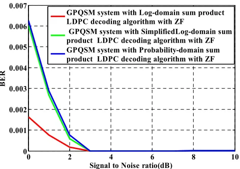
Figure 6. BER performance comparison of 5G Compatible LDPC channel encoded GPQSM Wireless Communication System with implementation Of various LDPC decoding algorithms, linear Zero-forcing (ZF) pre-coding and ZF signal detection schemes.
In Figure 6, with ZF signal detection scheme, the system performance under the implementation of Probability-domain sum product and Simplified log-domain sum product is not well discriminable from each other. The simulated system shows comparative better performance in Log Domain Sum-Product as compared to others two. For a typically assumed SNR value of 1dB, the estimated BER values are 0.0008, 0.0027 and 0.0029 in case of Log Domain Sum-Product, Simplified log-domain sum product and Probability-domain sum product which is indicative a system performance improvement of 5.59308 dB and 5.282738 dB in Log Domain Sum-Product as compared to Simplified log-domain sum product and Probability-domain sum product LDPC decoding algorithm.
5.
Conclusions
In this present paper, we have made a comprehensive study on performance evaluation of 5G Compatible LDPC encoded generalized pre-coding aided quadrature spatial modulation (GPQSM) scheme based wireless communication system. In addition to ML based signal detection, impact of additional signal detection schemes has changed the scenario of abrupt system performance enhancement in terms of Bit error rate. However, based on the simulation results for synthetic data transmission, it can be concluded that the presently considered ZF pre-coding adopted with LDPC channel encoded GPQSM wireless communication system is undoubtedly a robust system in perspective of signal transmission in hostile fading channel under the utilization of LDPC channel coding with the implemented log-domain sum product decoding algorithm and MMSE signal detection schemes.
Appendix
clear all; close all;
%reference_signal generation FFFFF = de2bi(0:255,'left-msb'); ncol=8;
nrow=256; for mmm=1:nrow
information_bits=FFFFF(mmm,:) ; %Separate information bits into three parts part1=information_bits(1,1:4);
part2=information_bits(1,5:6); part3=information_bits(1,7:8); %Symbol mapping
if(part1(1:2) ==[ 0 0 ]) symbol(1)=-1-sqrt(-1);
elseif(part1(1:2)==[ 0 1 ] symbol(1)=-1+sqrt(-1); elseif(part1(1:2)==[ 1 0 ])
symbol(1)=1- sqrt(-1); elseif(part1(1:2)==[ 1 1 ]) symbol(1)=1+sqrt(-1); end
if(part1(3:4) ==[ 0 0 ]) symbol(2)=-1-sqrt(-1); elseif(part1(3:4)==[ 0 1 ]) symbol(2)=-1+sqrt(-1); elseif(part1(3:4)==[ 1 0 ]) symbol(2)=1- sqrt(-1); elseif(part1(3:4)==[ 1 1 ]) symbol(2)=1+sqrt(-1); end
s=[symbol(1) symbol(2)]; %Indices mapping if(part2(1:2) ==[ 0 0 ]) I3I(1:2)=[ 1 3 ] ;
GPQSM_mapped_dataR(1,1)=real(s(1)); GPQSM_mapped_dataR(3,1)=real(s(2)); GPQSM_mapped_dataR(2,1)=0; GPQSM_mapped_dataR(4,1)=0; elseif(part2(1:2)==[ 0 1 ]) I3I(1:2)=[ 2 4 ] ;
GPQSM_mapped_dataR(2,1)=real(s(1)); GPQSM_mapped_dataR(4,1)=real(s(2)); GPQSM_mapped_dataR(1,1)=0; GPQSM_mapped_dataR(3,1)=0; elseif(part2(1:2)==[ 1 0 ]) I3I(1:2)=[ 1 4 ] ;
GPQSM_mapped_dataR(1,1)=real(s(1)); GPQSM_mapped_dataR(4,1)=real(s(2)); GPQSM_mapped_dataR(2,1)=0; GPQSM_mapped_dataR(3,1)=0; elseif(part2(1:2)==[ 1 1 ]) I3I(1:2)=[2 3 ] ;
GPQSM_mapped_dataR(2,1)=real(s(1)); GPQSM_mapped_dataR(3,1)=real(s(2)); GPQSM_mapped_dataR(1,1)=0; GPQSM_mapped_dataR(4,1)=0; end
%%%%%%%%%%%%%%%%%%%%%%% if(part3(1:2) ==[ 0 0 ])
0 2 4 6 8 10
0 0.001 0.002 0.003 0.004 0.005 0.006 0.007
Signal to Noise ratio(dB)
B
E
R
GPQSM system with Log-domain sum product LDPC decoding algorithm with ZF
I4Q(1:2)=[ 1 3 ] ;
GPQSM_mapped_dataI(1,1)=imag(s(1)); GPQSM_mapped_dataI(3,1)=imag(s(2)); GPQSM_mapped_dataI(2,1)=0;
GPQSM_mapped_dataI(4,1)=0; elseif(part3(1:2)==[ 0 1 ]) I4Q(1:2)=[ 2 4 ] ;
GPQSM_mapped_dataI(2,1)=imag(s(1)); GPQSM_mapped_dataI(4,1)=imag(s(2)); GPQSM_mapped_dataI(1,1)=0;
GPQSM_mapped_dataI(3,1)=0; elseif(part3(1:2)==[ 1 0 ]) I4Q(1:2)=[ 1 4 ] ;
GPQSM_mapped_dataI(1,1)=imag(s(1)); GPQSM_mapped_dataI(4,1)=imag(s(2)); GPQSM_mapped_dataI(2,1)=0;
GPQSM_mapped_dataI(3,1)=0; elseif(part3(1:2)==[ 1 1 ]) I4Q(1:2)=[2 3 ] ;
GPQSM_mapped_dataI(2,1)=imag(s(1)); GPQSM_mapped_dataI(3,1)=imag(s(2)); GPQSM_mapped_dataI(1,1)=0;
GPQSM_mapped_dataI(4,1)=0; end
GPQSM_mapped_data=GPQSM_mapped_dataR+sqrt(-1)*GPQSM_mapped_dataI;
reference_signal(:,mmm)=GPQSM_mapped_data; end
information_bits=[ 0 1 1 0 1 0 1 1 ]; part1=information_bits(1,1:4); part2=information_bits(1,5:6); part3=information_bits(1,7:8); %Symbol mapping
if(part1(1:2) ==[ 0 0 ]) symbol(1)=-1-sqrt(-1); elseif(part1(1:2)==[ 0 1 ]) symbol(1)=-1+sqrt(-1); elseif(part1(1:2)==[ 1 0 ]) symbol(1)=1- sqrt(-1); elseif(part1(1:2)==[ 1 1 ]) symbol(1)=1+sqrt(-1); end
if(part1(3:4) ==[ 0 0 ]) symbol(2)=-1-sqrt(-1); elseif(part1(3:4)==[ 0 1 ]) symbol(2)=-1+sqrt(-1); elseif(part1(3:4)==[ 1 0 ]) symbol(2)=1- sqrt(-1); elseif(part1(3:4)==[ 1 1 ]) symbol(2)=1+sqrt(-1); end
s=[symbol(1) symbol(2)]; %Indices mapping if(part2(1:2) ==[ 0 0 ]) I3I(1:2)=[ 1 3 ] ;
GPQSM_mapped_dataR(1,1)=real(s(1)); GPQSM_mapped_dataR(3,1)=real(s(2));
GPQSM_mapped_dataR(2,1)=0; GPQSM_mapped_dataR(4,1)=0; elseif(part2(1:2)==[ 0 1 ]) I3I(1:2)=[ 2 4 ] ;
GPQSM_mapped_dataR(2,1)=real(s(1)); GPQSM_mapped_dataR(4,1)=real(s(2)); GPQSM_mapped_dataR(1,1)=0; GPQSM_mapped_dataR(3,1)=0; elseif(part2(1:2)==[ 1 0 ]) I3I(1:2)=[ 1 4 ] ;
GPQSM_mapped_dataR(1,1)=real(s(1)); GPQSM_mapped_dataR(4,1)=real(s(2)); GPQSM_mapped_dataR(2,1)=0; GPQSM_mapped_dataR(3,1)=0; elseif(part2(1:2)==[ 1 1 ]) I3I(1:2)=[2 3 ] ;
GPQSM_mapped_dataR(2,1)=real(s(1)); GPQSM_mapped_dataR(3,1)=real(s(2)); GPQSM_mapped_dataR(1,1)=0; GPQSM_mapped_dataR(4,1)=0; end
%%%%%%%%%%%%%%%%%%% if(part3(1:2) ==[ 0 0 ])
I4Q(1:2)=[ 1 3 ] ;
GPQSM_mapped_dataI(1,1)=imag(s(1)); GPQSM_mapped_dataI(3,1)=imag(s(2)); GPQSM_mapped_dataI(2,1)=0;
GPQSM_mapped_dataI(4,1)=0; elseif(part3(1:2)==[ 0 1 ]) I4Q(1:2)=[ 2 4 ] ;
GPQSM_mapped_dataI(2,1)=imag(s(1)); GPQSM_mapped_dataI(4,1)=imag(s(2)); GPQSM_mapped_dataI(1,1)=0;
GPQSM_mapped_dataI(3,1)=0; elseif(part3(1:2)==[ 1 0 ]) I4Q(1:2)=[ 1 4 ] ;
GPQSM_mapped_dataI(1,1)=imag(s(1)); GPQSM_mapped_dataI(4,1)=imag(s(2)); GPQSM_mapped_dataI(2,1)=0;
GPQSM_mapped_dataI(3,1)=0; elseif(part3(1:2)==[ 1 1 ]) I4Q(1:2)=[2 3 ] ;
GPQSM_mapped_dataI(2,1)=imag(s(1)); GPQSM_mapped_dataI(3,1)=imag(s(2)); GPQSM_mapped_dataI(1,1)=0;
GPQSM_mapped_dataI(4,1)=0; end
GPQSM_mapped_data=GPQSM_mapped_dataR+sqrt(-1)*GPQSM_mapped_dataI;
x=GPQSM_mapped_data;
% 4X 6 MIMO channel generation, 6 transmitting and 4 receiving antenna
H=sqrt(1/2)*(randn(4,6)+sqrt(-1)*randn(4,6)); % MIMO channel : 4 x 6
% Normalization of channel matrix for kk=1:6
H(kkk,kk)=H(kkk,kk)/ (abs(H(kkk,kk))); end
end
channel_normalization=(norm( H,'fro')).^2 ; % its value would be 4 x 6=24
%ZF based precoding P=H'*inv(H*H'); D=sum(abs(P).^2); D=diag([D]);
D=sqrt(inv(D)); % 4 x 4
HP=H*P; % Identity matrix,verified Y=H*P*D*x;
%HP=H*P; % Identity matrix, %%%%%%%%%%%%%%%%%% %AWGN noise addition, SNR=10dB; SNR=10;
power_linear=db2pow(SNR) ; % signal power/ noise power
for kk=1:4
signal_power(kk,1)=sum(abs(Y(kk,1).^2));
noise_power(kk,1)=signal_power(kk,1)/power_linear; noise_amplitude(kk,1)=sqrt(noise_power(kk,1)/2); Noisy_term(kk,1)=noise_amplitude(kk,1)*[randn(1,1)+sqr t(-1)*randn(1,1) ] ;
end
w=Noisy_term; Y=Y+w; % Equ 2.17 %ML decoding
for k=1:length(reference_signal)
compare(1,k)= (norm( (Y-D*reference_signal(:,k)), 'fro')).^2 ;
end
%%%%%%%%%%%%%%%%%%%%%%% [minimum_value,integer_value] = min(compare); GPQSM_mapped_data
xhat=reference_signal(:,integer_value); GPQSM_mapped_dataRR=real(xhat); GPQSM_mapped_dataII=imag(xhat);
%%%%%%%%%%%%%%%%%%%%%%% if( (GPQSM_mapped_dataRR(2,1)==0) && (GPQSM_mapped_dataRR(4,1)==0) )
sR(1)=GPQSM_mapped_dataRR(1,1); sR(2)=GPQSM_mapped_dataRR(3,1); part22(1:2) =[ 0 0 ]
elseif( (GPQSM_mapped_dataRR(1,1)==0) && (GPQSM_mapped_dataRR(3,1)==0) )
sR(1)=GPQSM_mapped_dataRR(2,1); sR(2)=GPQSM_mapped_dataRR(4,1); part22(1:2) =[ 0 1 ]
elseif( (GPQSM_mapped_dataRR(2,1)==0) && (GPQSM_mapped_dataRR(3,1)==0) )
sR(1)=GPQSM_mapped_dataRR(1,1); sR(2)=GPQSM_mapped_dataRR(4,1); part22(1:2) =[ 1 0 ]
elseif( (GPQSM_mapped_dataRR(1,1)==0) && (GPQSM_mapped_dataRR(4,1)==0) )
sR(1)=GPQSM_mapped_dataRR(2,1);
sR(2)=GPQSM_mapped_dataRR(3,1); part22(1:2) =[ 1 1 ]
end
if( (GPQSM_mapped_dataII(2,1)==0) && (GPQSM_mapped_dataII(4,1)==0) )
sI(1)=GPQSM_mapped_dataII(1,1); sI(2)=GPQSM_mapped_dataII(3,1); part33(1:2) =[ 0 0 ]
elseif( (GPQSM_mapped_dataII(1,1)==0) && (GPQSM_mapped_dataII(3,1)==0) )
sI(1)=GPQSM_mapped_dataII(2,1); sI(2)=GPQSM_mapped_dataII(4,1); part33(1:2) =[ 0 1 ]
elseif( (GPQSM_mapped_dataII(2,1)==0) && (GPQSM_mapped_dataII(3,1)==0) )
sI(1)=GPQSM_mapped_dataII(1,1); sI(2)=GPQSM_mapped_dataII(4,1); part33(1:2) =[ 1 0 ]
elseif( (GPQSM_mapped_dataII(1,1)==0) && (GPQSM_mapped_dataII(4,1)==0) )
sI(1)=GPQSM_mapped_dataII(2,1); sI(2)=GPQSM_mapped_dataII(3,1); part33(1:2) =[ 1 1 ]
end
s11=sR(1)+sqrt(-1)*sI(1) s22=sR(2)+sqrt(-1)*sI(2) if( s11==(-1-j))
first_bits=[ 0 0 ] elseif( s11==(-1+j)) first_bits=[ 0 1 ] elseif( s11==(1-j)) first_bits=[ 1 0 ] elseif( s11==(1+j)) first_bits=[ 1 1 ] end
if( s22==(-1-j)) second_bits=[ 0 0 ] elseif( s22==(-1+j)) second_bits=[ 0 1 ] elseif( s22==(1-j)) second_bits=[ 1 0 ] elseif( s22==(1+j)) second_bits=[ 1 1 ] end
retrieved_bits=[first_bits second_bits part22 part33]; [number,bit_errorr_rate]=biterr(retrieved_bits,information _bits)
References
[1] Wei Xiang, Kan Zheng and Xuemin (Sherman) Shen, 2017: 5G Mobile Communications, Springer International Publishing, Switzerland
[3] Beixiong Zheng; Miaowen Wen; Ertugrul Basar; Fangjiong Chen, 2017: Multiple-Input Multiple-Output OFDM With IndexModulation: Low-Complexity Detector Design, EEE Transactions on Signal Processing, vol. 65, no. 11, pp. 2758 – 2772
[4] R. Mesleh, et al., “Spatial modulation,” IEEE Trans. Veh. Technol., vol. 57, no. 4, pp. 2228-2241, July 2008.
[5] Miaowen Wen, Xiang Cheng and Liuqing Yang, 2017: Index Modulation for 5G Wireless Communications, Springer International Publishing, Switzerland
[6] R. G. Gallager, Low Density Parity-Check Codes. MIT Press, Cambridge, MA, 1963
[7] Arun Avudaunayagam, http://arun10.tripod.com/ldpc/ldpc.htm [8] Bagawan Sewu Nugroho,
https://sites.google.com/site/bsnugroho/ldpc
[9] Yong Soo Cho, Jackson Kim, Won Young Yang, Chung G. Kang, 2010: MIMO-OFDM Wireless Communications with [10] Lin Baiand Jinho Choi, Low Complexity MIMO Detection,
Springer Science and Business Media, LLC, New York, USA, 2012.
Biography
Md. Tahin Hossain is working as a lecturer in the Department of Electrical and Electronic Engineering, Prime University, Dhaka Bangladesh. He received his B. Sc. (Hons.) and M. Sc. degree both from the Department of Applied Physics and Electronic Engineering, University of Rajshahi, Bangladesh in 2012 and 2013 respectively. During his post graduate study, he completed a 4G compatible cellular standard based research work. His research interest is oriented with applicability of various 5G based radio interface technologies( Index Modulation, OFDM-IM, FBMC, NOMA, Pattern division multiple access(PDMA), Video signal transmission in mmWave massive MIMO system and 3D MIMO beam forming techniques.
Indraneel Misra is working as an Assistant Professor and Head in the Department of Computer Science and Engineering, School of Science and Engineering, Khwaja Yunus Ali University, Bangladesh. He received his B. Sc. (Hons.) and M. Sc. degree both from the Department of Information and Communication Engineering, University of Rajshahi, Bangladesh in 2011 and 2012 respectively. During his graduate study, he completed a research work on performance study of OFDM system. His research interest is concerned with applicability of useful techniques used in 3D MIMO beam forming, detection in massive MIMO, Index Modulation, FBMC and NOMA on audio and video signal transmission.
Joarder Jafor Sadique is working as a lecturer in the Department of Electronics and Telecommunication Engineering, Begum Rokeya University, Bangladesh. He also served as a lecturer in the Department of Electrical and Electronic Engineering of a private university of Bangladesh. He received his B. Sc. (Hons.) and M. Sc. degree both from the Department of Applied Physics and Electronic Engineering of University of Rajshahi, in 2010 and 2011 respectively. During his post graduate study, he completed a research work on MIMO SC-FDMA system. His research interest includes Cooperative communications, Precoding for mmWave massive MIMO, filtered OFDM, NOMA, FBMC, FSO and Channel Equalization
![Figure 1. Structural feature of GPQSM transceiver [5].](https://thumb-us.123doks.com/thumbv2/123dok_us/9897750.1977245/2.595.56.542.490.709/figure-structural-feature-gpqsm-transceiver.webp)