INTRODUCTION
Analysis of str uctures under base excitation is extremely important, and it is usually performed, in the aerospace industry. The aim of the analysis is to verify the structural integrity of the space hardware, i.e., spacecraft, spacecraft antenna, electronic boxes, etc. when exposed to a sinusoidal or random base-excitation environment. To identify the effective modes, the effective-mass concept was introduced and developed in the early seventies1,2, and used intensely, in particular, in the aerospace industry3-7. Since that time, extensive use of this concept has been made in various fields of structural dynamics.
The effective-mass concept is directly related to modal reaction forces and can be
Material Science Research India Vol. 5(2), 209-218 (2008)
Influence of modal effective mass distribution
on the static and dynamic behavior of a satellite
structure under base excitations
HAMID EMAMI, FOAD FARHANI
1and MAJID SAFARABADI
Mechanical Engineering Department, Iranian Research
Organization for Science and Technology (IROST), P.O. Box 15815 - 3538 (Iran). (Received: October 10, 2008; Accepted: November 25, 2008)
ABSTRACT
Effective mass is a dynamic property of a structure associated with the modal characteristics; natural frequencies and mode shapes. It is a measure used to classify the importance of a mode when a structure is accelerated via its base. Additionally, a structure under acceleration loads can be affected by the distribution of modal effective masses in different frequencies. Hence, cumulating the effective mass in one frequency may cause a considerable reaction force in the structure. In this paper, effect of structural stiffening in a small satellite structure has been studied. Results show that both the dynamic response and equivalent static loads can be affected by characteristic of stiffening, which is a direct consequence of spreading of modal effective masses among more frequencies. Results of analyses performed on access doors of different geometries, with reinforcement frames having different stiffness, show that for the case of constant satellite structure total mass, the equivalent loads due to random vibrations and shock phenomenon change by 33% and 91%, respectively.
Key words: Modal effective mass, Random vibration, Shock phenomenon, Normal frequency, Reinforcement frames.
interpreted as a measure of the modal reaction forces to the unit-driven base acceleration. It is a very useful tool for many purposes such as: a better understanding of the dynamic behavior of a structure in base-excitation dynamics, the predicting of the force limit in force-limited vibration testing, detection and selection of important modes for a given response, and evaluation of truncation effects using the residual mass8.
provides suitable accommodation in the upper module for thermally sensitive components such as batteries. In the lower module, in contact with the base plate, vibration sensitive components such as electrical boards can be accommodated for minimizing transmission of vibration from the launcher. In addition, provision of access doors on the satellite lateral sides in the upper and low modules results in the flexibility of this structure with respect to component layout and access to different satellite components during various stages of assembly and integration. Therefore, this structure can be used for missions with different requirements, as it needs minimum change in configuration, has the lowest cost, and takes minimum time for assembly and integration.
In view of the basic requirement of the satellite structure, namely protecting other subsystems form loads transmitted by the satellite launcher, the effect of access doors geometry, and specifications of their reinforcement frame sections on the amount of transmitted loads have been studied.
The study shows that geometry of the access doors and specifications of frame section influences the distribution of effective masses related to the vibration modes in normal coordinates and in the specific location related to various modes of the lateral plates. This affects the dynamic behavior of structure and magnitude of analytical random vibrations and shock loads, appreciably. These analyses help in the selection of most suitable frames geometry and moment of inertia for the section reinforcement, aiming at minimizing loads acting on the satellite structure. Additionally, sensitivity of analyses to modeling of reinforcement section has been studied. In this research work, NASTRAN-PATRAN software has been used for normal modes, and NASA Codes have been used for determination of equivalent loads [9].
Applied forces on the satellite structure A satellite structure provides the necessary mechanical support for all satellite subsystems including attitude control, batteries, thermal control, on board computer, etc. The structure must withstand the static and dynamic loads from the launcher during the satellite launch and injection in to its final orbit.
The satellite base plate is attached to the launcher through an interface. In about ten minutes during which the launcher transfers the satellite to its final orbit, the satellite structure is acted upon by static and dynamic loads. These loads are considered in the design of the satellite structure. The propulsive thrust of the launcher produces an almost constant propulsive force along the launcher axis. Acceleration increases slightly with the decrease in the launcher fuel mass, and ceases completely on complete consumption of the fuel. Satellite launchers are usually of multistage type. Therefore, the above process may induce nearly constant acceleration to the satellite, many times with different intensities. Satellite manufacturers usually present the acceleration values as multiples of gravitational acceleration in three main directions (one along the launch direction, and two in direction perpendicular to the launch direction). These acceleration values basically demonstrate the inertial phenomenon, which is applied to all the satellite components in the form of inertial forces10. In addition to this effect, gravitational acceleration graphs based on frequency show the transient effect of this phenomenon at low frequencies (between 20 to 200 Hz).
Another source of applied load on the satellite structure during the launch period is the random vibrations due to launcher engine and its related parts and components. During lift off, the main cause of these random vibrations is the acoustic loads due to engine noise. Beside this factor, the random vibrations caused by aerodynamic forces due to supersonic speed achieved by the launcher. The combination of these vibrations is transmitted to the satellite through the rocket structure. At the same time, satellite structural elements, with large area to mass ratios (e.g. solar panels) are directly and severely affected by the acoustic phenomenon. Loads resulting from random phenomenon can not be expressed as multiple of gravitational acceleration. The three variables which help describe the random vibrations are: type of distribution, frequency content, and magnitude of these vibrations.
is defined (determined). For expression of frequency content, the power spectral density unit is used (for this specific application, the term acceleration is a better choice). In order to obtain a quantity independent of the width, this quantity is divided over the frequency band width over which integration is carried out. Therefore, the required variable will have the g2/Hz unit. To show the PSD, use is made of logarithmic axes, and for expressing its value, the unit g2/Hz is used against the frequency variation. These vibrations lie in 20 to 2000 Hz frequency range.
The third source of applied load to the structure is due to the shock phenomenon, resulting from separation of satellite from its launcher. To produce the suitable initial velocity in the satellite, it is necessary to apply a big acceleration in a very short period (time span). This may be achieved using explosive mechanisms. Other phenomena such as separation of antenna and deployment of solar panels can also cause shock. However, normally 90% of the shock phenomenon is caused by separation of satellite from its launcher.
The main loads due to launch conditions are placed in the 3 groupings given above. The satellite structure due to the above conditions will bear reactive inertial forces due to the transmitted accelerations from the satellite base plate. The design of the satellite structure is based on the application of equivalent accelerations as multiples of gravitational acceleration for various loading conditions, considering the load factors from the launcher manual¹¹. The calculated stresses during the worst loading conditions are compared with the yield point and tensile strength to determine the safety factors.
Calculation of equivalent static loads due to random vibrations
Based on research by Miles¹², in the case of base excitation phenomenon of a system with one degree of freedom, consisting of spring and mass, with random vibration of constant amplitude of white noise type with constant frequency range of 0 to infinity, the loads due to random vibrations can be expressed on basis of gravitational acceleration.
In recent years, a method has been developed for extension of this relation (equation) to include systems of n degrees of freedom. It can be shown that using decoupled equations in a particular coordinate system, for base excitation phenomenon of a system with n degrees of freedom, the dynamic characteristics of the system can be expressed on basis of normal modals and effective masses¹³.
The normal modes and effective masses define specific directions in which the acceleration is independent related to the frequency and mode shape of that frequency. On the other hand the absorbed energy for movement in that specific direction is linearly related to effective mass, defined for that particular mode. (The total effective masses are equivalent to the total mass of structure, and therefore, amount of effective mass for each mode expresses the specific share of that mode in the total vibrations of the system¹³).
Under such conditions, the Miles equation for systems with n degrees of freedom can be expressed as following:
...(1)
...(2)
...(3)
The equivalent load factor as a multiple of gravitational acceleration is calculated using Eq. (1). In the above equations, fi and Wi are natural frequency and PSD value at ith mode, respectively. Q is the amplification factor. Value of Pi for each of the selected modes is determined using Eq. (2). In this equation, meff,i is the effective mass obtained at ith mode and gravitational acceleration g.
Table 1: Combination of loadings due to impulse force from the launcher random vibration
Load Case LAT X LAT Y AXIAL (Z)
1-8
9-16
17-24
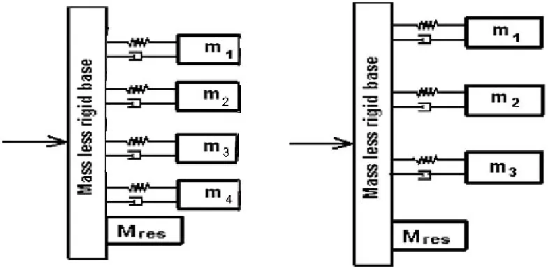
of smaller terms, and therefore, the numerator in the fraction decreases, consequently decreasing the resultant equivalent loads. The physical interpretation of the effective masses and effect of modes break-down are shown in Fig. 1. Overall, the base excitation for the structure with distributed effective masses produces weaker reactions in the base.
The residual-mass matr ix is the summation of the effective-mass matrix above the excitation frequency, which reflects the effect of truncation. Assuming the natural frequencies of the excluded modes to be significantly higher than the
excitation frequency, the residual mass may be interpreted as the fraction of the total structural mass, which moves with the input acceleration without any amplification factor.
Of the three groups of loads acting on the structure, the third group, the forces resulting from the shock, act on the structure when different modules in the launcher propulsion system have completed their functions. The first two groups can exist in combination. The resultant loads due to the shock phenomenon are act on the structure, independently. Table 1 presents the combination load values resulting from first and second phenomenon.
Fig. 2: The satellite structure finite element model
Fig. 3: Satellite model with elliptical access doors
Fig. 4: Distribution of effective masses on basis of second moment of inertia of the
elliptical reinforcement sections and corresponding frequencies
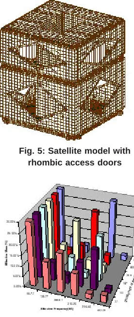
Fig. 5: Satellite model with rhombic access doors
Figure 6: Distribution of effective masses on basis of second moment of inertia of the
rhombic reinforcement sections and corresponding frequencies
Fig. 7: Satellite model with rectangular access doors
Table 2: Type and number of elements used in the finite element model Number Element Type Element Name
946 CBAR Beam element
3080 CHEXA Solid element
34 CPENTA Solid element
27 CONM2 Concentrated mass
19268 CQUAD4 Shell elements 594 CTRIA3 Shell elements 31 RBE2 Multi-Point Constraint
Table 3: Distribution of effective masses for the satellite model with elliptical access doors Frequency Range (HZ)
280-288 288-289 289-290 290-292 292-295 295-305
2nd Moment Effective Effective Effective Effective Effective Effective
Mass (%) Mass (%) Mass (%) Mass (%) Mass (%) Mass (%)
27 0.00% 0.00% 0.00% 30.09% 1.07% 1.71%
100 0.00% 1.14% 2.87% 9.36% 17.17% 1.53%
147 3.18% 0.00% 21.26% 0.00% 2.40% 5.57%
265 0.00% 0.00% 14.94% 15.09% 1.37% 1.10%
400 0.00% 1.96% 12.82% 16.06% 1.20% 0.00%
600 0.00% 0.00% 27.22% 1.05% 2.23% 1.90%
Table 4: Resultant accelerations for the satellite model with elliptical access doors 2nd Moment Shock Random Vibration of Area (mm^4) Load (g) Load factor (g)
27 35.4 22.57
100 20.3 16.95
147 24.9 18.38
265 17.8 17.18
400 18.9 16.97
300 32 21.88
In the above equations, RVL is the equivalent load due to random vibrations and QSL is the equivalent quasi static load due to of the first type phenomena. Considering the positive and negative signs, the above equations define 24 loading conditions. Calculation of loads due to shock phenomenon
After specification of components of normal modes in coordinate directions, the shock response curve (graph) is used to calculate loads equivalent to shock loads, Si, for each mode on basis of corresponding frequency for that mode. Multiplication of the quantities, so obtained, with the
corresponding effective mass for each mode, gives the shock force at that mode.
Intensity of the equivalent shock force on the structure in any direction equals the maximum force obtained for different modes in that particular direction, and is obtained using the following relation:
...(4)
In the above relation, is the effective mass obtained at the ith mode, and is the total mass of the satellite structure. The finite element model used
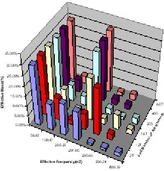
Fig. 8: Effective masses distribution on basis of second moment of inertia of the
rectangular reinforcement sections and corresponding frequencies
Fig. 9: Shock acceleration value on basis of second moment of inertia for reinforcement sections in structure of different geometries
Fig. 10: Equivalent acceleration determined on basis of second moment of inertia for
reinforcement sections in structures of different geometries
location, the electronic boards withstand the minimum vibrations transmitted from the launcher. In addition, due to the access doors placed on the upper and lower module, the structure has the required flexibility for optimum component lay-out and easy access to the components in various stages of assembly, integration and test.
In order to study the effect of access doors geometr y, doors of elliptical, rhombic and rectangular geometries have been modeled. Additionally, to study the effect of stiffness of door frames for each model, moment of inertia of frame sections have been also modeled. In all the constructed models, for purpose of analysis, mass has been kept constant. The satellite structure dimensions are: 500* 500* 500 mm, and the total structure mass including all the internal components is 76 kg.
Modeling of plates has been done using Shell elements. To study the stress behavior in the thickness direction, and imposing the relevant boundary conditions, Solid elements have been used for modeling of thick sections of the satellite structure. Modeling of joints has been done using Beam elements coupled with the central element. With this arrangement, areas containing the central beam element and its surrounding elements, experience similar displacements due to the acting forces. Small non-structural elements (such as magnetometers, etc) have been modeled using Concentrated mass element. For modeling of bolts, rivets, thermal control hardware, and electrical harness, non-structural mass elements have been used. Figure 2 shows the finite element model of one of the analyzed structures. Type and number of elements used in this FEM model are presented in Table 2. Access doors of rectangular, rhombic and elliptical shapes have been modeled considering reinforcement frames with variable second moment of inertia for cross section. The analysis results
In order to compare behavior of different structures, Cosmos launcher Interface Compatibility Document (ICD) [11] has been used.
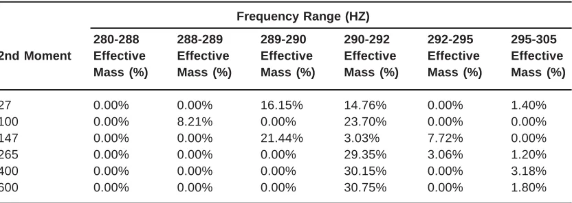
Table 7: Distribution of effective masses for the satellite model with elliptical access doors Frequency Range (HZ)
280-288 288-289 289-290 290-292 292-295 295-305
2nd Moment Effective Effective Effective Effective Effective Effective
Mass (%) Mass (%) Mass (%) Mass (%) Mass (%) Mass (%)
27 0.00% 0.00% 16.15% 14.76% 0.00% 1.40%
100 0.00% 8.21% 0.00% 23.70% 0.00% 0.00%
147 0.00% 0.00% 21.44% 3.03% 7.72% 0.00%
265 0.00% 0.00% 0.00% 29.35% 3.06% 1.20%
400 0.00% 0.00% 0.00% 30.15% 0.00% 3.18%
600 0.00% 0.00% 0.00% 30.75% 0.00% 1.80%
Table 5: Distribution of effective masses for the satellite model with rhombic access doors Frequency Range (HZ)
280-288 288-289 289-290 290-292 292-295 295-305
2nd Moment Effective Effective Effective Effective Effective Effective
Mass (%) Mass (%) Mass (%) Mass (%) Mass (%) Mass (%)
27 0.00% 0.00% 18.44% 10.26% 2.39% 1.74%
100 0.00% 11.71% 0.00% 18.94% 0.00% 2.03%
147 0.00% 0.00% 2.76% 21.51% 6.09% 1.14%
265 0.00% 0.00% 22.78% 5.01% 3.84% 0.00%
400 1.05% 0.00% 25.14% 4.94% 0.00% 1.06%
600 2.14% 1.66% 0.00% 28.16 0.00% 0.00%
Table 6: Resultant accelerations for the satellite model with rhombic access doors 2nd Moment Shock Random Vibration of Area (mm^4) Load (g) Load factor (g)
27 21.7 17.43
100 22.3 17.66
147 25.3 18.49
265 26.7 18.95
400 29.6 21.38
300 33.2 22.82
do not change appreciably with change in configuration of lateral plates in direction perpendicular to these plates. Therefore, change in equivalent structural loads and the modal behavior of the structure in the launch direction (Z direction) have been considered.
Effect of geometr y of access doors and specifications of their frame sections, has been studied by constructing different models. In all the constructed models, mass of satellite structure has been considered to be constant. Behavior of different structures has been studied by changing the overall shape of lateral access doors and the specifications of rectangular reinforcement frames. These reinforcement frames are sued to facilitate bolting of the thick plates of 1.6 mm thickness.
It has been observed that although sum of effective masses does not change appreciably in vibration modes range related to the lateral plates, in practice the distribution (the modal break-down) in the desired frequency range, is function of specifications of the reinforcement frames.
Distribution of effective masses for different lateral reinforcement frame sections in the launch direction is shown in Fig. 4. As shown, in the frequency range considered, the distributed effective mass is a function of moment of inertia of the reinforcement frame sections.
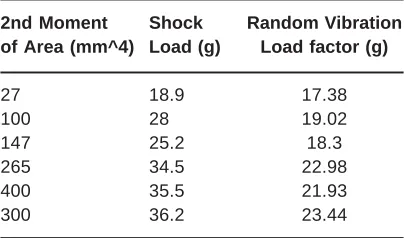
The impor tance and effect of each vibration mode depends on effective mass of the corresponding mode. Therefore, a large number of local modes with low effective masses can be ignored. Practical considerations show that effective modes with effective masses less than 10% can be omitted without any appreciable effect on the response. Table 3 shows the distribution of modes in a specific range. Table 4 presents the equivalent forces (accelerations) due to the random vibrations and shock phenomenon for few frame sections.
The structure model with rhombic access doors is shown in Fig. 5. Distribution of effective masses for different frame sections is shown in Fig. 6. Distribution of effective masses higher than 10% is shown in Table 5. Equivalent loads due to random vibrations and shock phenomenon are given for rhombic reinforcement frames in Table 6.
The structural model with rectangular access doors is shown in Fig. 7. Distribution of modes in a particular range is shown in Fig. 8. The corresponding effective masses and equivalent loads are shown in Tables 7 and 8, respectively.
RESULTS AND DISCUSSIONS
In this paper, effect of geometry and specifications of reinforcement frames sections in a double module cubical satellite structure on the dynamic behavior of the structure has been studied. As indicated, for a model of constant mass, access doors with var ying moment of iner tia of the reinforcements, the moment of iner tia of the
reinforcements has profound effect on the distribution of the effective masses due to the modes of the lateral plates (modes in the range of 280-305 Hz). At the same time, the summation of the effective masses within the range of vibration modes related to the lateral plates does not show appreciable variation. Therefore, specifications of the reinforcement sections affect the distribution of effective masses related to the vibration modes in normal coordinates and in a specific location related to different modes of lateral plates, greatly influencing the dynamic behavior of the structure and the magnitude of analytical loads due to the random vibrations and shock phenomenon. The observed effects are 33% for loads resulting from random vibrations and 91% for equivalent loads resulting from the shock phenomenon. In addition, these analyses demonstrate the sensitivity of accurate modeling of reinforcement frames in the satellite structure. For example, a 12*3 structural reinforcement section with elliptical access doors having 6.5*5.5 sections produces about 30% change in the equivalent loads due to random vibrations, and a change in the equivalent loads due to shock phenomenon of about 67%.
Figures 9 and 10 present graphs of acceleration due to shock phenomenon and random vibrations, on basis of the second moment of inertia of reinforcement frame sections in satellite models with different lateral plate geometries. As shown, in case of models with rectangular and rhombic access doors, the resultant accelerations in most points (locations) are relatively high, while for models with elliptical access doors, the average acceleration values obtained lie in a wide range.
Table 8: Resultant accelerations for the satellite model with rectangular access doors 2nd Moment Shock Random Vibration of Area (mm^4) Load (g) Load factor (g)
27 18.9 17.38
100 28 19.02
147 25.2 18.3
265 34.5 22.98
400 35.5 21.93
300 36.2 23.44
1. Bamford, R.M., Wada, B.K., Garba, J.A.,"Equivalent Spring-Mass System for Normal Modes", Tech. Memo. 33-380, Jet Propulsion Laboratory, (1971).
2. Wada, B.K., Bamford, R.M., Gayman, W.H., "Equivalent Spr ing-Mass– A Physical Interpretation", Shock Vib. Bull. No. 42: 215- 225 (1972).
3. Imbert, J.F., "A Survey of Current Capability for Dynamic Analysis of Complex Structures", World Congress on Finite Element Methods, Bornemouth, (1978).
4. Girard, A., Imbert, J.F., "Modal Effective Mass Models in Structural Dynamics", Proceedings of the 9th International Modal Analysis Conference, Florence, Italy, (1991). 5. Fullekrug, U. "Determination of Effective-masses and Modal Masses from Base-Driven Tests", Proceedings of the 14th International Modal Analysis Conference, Dearborn, Michigan, USA (1996).
6. Girard, A., Dupuis, P.E., Bugeat, L.P., “Evaluation of the Dynamic Mass of a Specimen on a Shaker”, Conference on Spacecraft Structures, Materials & Mechanical Testing, Braunschweig,
REFERENCES
Germany, (1998).
7. Draisey, S., "International Space Station, a Deployment and Modal Test Facility", 53rd International Astronautical Congress: World Space Congress-2002, Houston, Texas, (2002).
8. Sedaghati, R., Soucy, Y., Etiene, N., "Efficient Estimation of Effective Mass for Complex Structures under Base excitations," CASI, 49(3), September (2003).
9. "Payload Flight Equipment Requirements and Guidelines for Safety–Cr itical Str uctures", SSP 52005 Revision C, December 18 (2002).
10. Larson, W., Wer tz, J., "Space mission analysis and design", 3rd edition, Microcosm Inc, (1999).
11. "Cosmos Launch System", Payload User’s Manual 2.1 (1999).
12. Miles, G.W., "On Structural Fatigue Under Random Loading", J. Aeronautical Sciences, pp. 753, November (1954).