Abstract— Transmission networks of modern power systems
are becoming increasingly stressed because of growing demand and restrictions on building new lines. One of the consequences of such a stressed system is the threat of losing stability following a disturbance. Flexible ac transmission system (FACTS) devices are found to be very effective in a transmission network for better utilization of its existing facilities without sacrificing the desired stability margin. Flexible AC Transmission System (FACTS) such as Static Synchronous Compensator (STATCOM) employ the latest technology of power electronic switching devices in electric power transmission systems to control voltage and power flow. A static synchronous compensator (STATCOM) is a shunt device of the flexible AC transmission systems (FACTS) family. The STATCOM regulates voltage at its terminal by controlling the amount of reactive power injected into or absorbed from power system. When system voltage is low, STATCOM generates reactive power and when system voltage is high it absorbs reactive power. In this paper, the effect of STATCOM for improving the stability of the multi machine power system with three phase fault and without three phase fault condition is investigated. The performance and behavior of this shunt controller is tested in MATLAB/Simulink.
Index Terms— STATCOM, FACTS, Stability,Multi Machine.
I. INTRODUCTION
We are facing the problem of below marked availability of electrical energy. The root causes lie scare city of generation and supply along with rapidly increasing demand for power because of developmental activities. Simultaneously there is increasing the tendency of over exploitation of existing facilities of generation and supply. This over exploitative trends have created in stability in power system. So facts are that power generation rate is lower than power consumption rate. Transmission network and facilities are also trailing. To keep maintain the production and development in agriculture and industrial production there is pressure for making available more and more power. In such a situation, how can we coop the existing problems. We try to find help for the solution to these problems from technology.
As a help, in such a situation, there is idea of quality of flexibility in power system. The important and basic rule in power system is that at all the times the value of load and the amount of power generated must match with in a limit. There becomes a quality of self-regulation in power system. In case the amount of generation is less than load demand there occurs drop in frequency and voltage of the power. Its effects becomes that the load reduces down and equalize itself to the generated minus power as losses. But there are only a
few percent margins for such a self-regulation. Hence there is chance of system collapse. Generator excitation controller with only excitation control can improve transient stability for minor faults but it is not sufficient to maintain stability of system for large faults occur near to generator terminals. Thus, this requires a review of traditional methods and the creation of new concepts that emphasize a more efficient use of already existing power system resources without reduction in system stability and security. In the late 1980s, the Electric Power Research Institute (EPRI) introduced a new approach to solve the problem of designing and operating power systems; the proposed concept is known as Flexible AC Transmission Systems (FACTS). The two main objectives of FACTS are to increase the transmission capacity and control power flow over designated transmission routes. FACTS are defined by the IEEEas "a power electronic based system and other static equipment that provide control of one or more AC transmission system parameters to enhance controllability and increase power transfer capability.
Basically, FACTS controllers can be divided into four categories:
1) Series Controller 2) Shunt Controller
3) Combined series-series Controller 4) Combined series-shunt Controller
Name Type Purpose
STATCOM Shunt Voltage Control
SVC Shunt Voltage Control
SSSC Series Power Flow Control
TCSC Series Power Flow Control
UPFC Shunt & Series Voltage & Power Flow Control
TCPAR Shunt & Series Power Flow Control
Table 1.1: Comparison among FACTS Controllers. Typical applications of FACTS in power system are: 1) Effective voltage regulation and control.
2) Reduction of temporary overvoltage.
3) Improvement of steady-state power transfer capacity 4) Damping of power system oscillations.
5) Power quality improvement.
II. STATIC SYNCHRONOUS COMPENSATOR
The concept of the STATCOM was proposed by Gyugyi in 1976. According to IEEE a STATCOM can be defined as a static synchronous generator operated as a shunt-connected static var compensator whose capacitive or inductive output current can be controlled independent of the AC system voltage.
Modelling & Performance Analysis of Multigrid
Transmission Network Using Statcom
A STATCOM is a static compensator that it is connected to the grid in parallel for the compensation of reactive power. It is able to inject or absorb reactive power in a controlled way regardless of the grid voltage [1, 2]. The basic element is the Voltage Source Converter (VSC) which converts an input DC voltage to an AC voltage at the fundamental frequency with a given magnitude and a controllable phase. The AC output voltage is dynamically controlled in order to provide the required reactive power to the network.
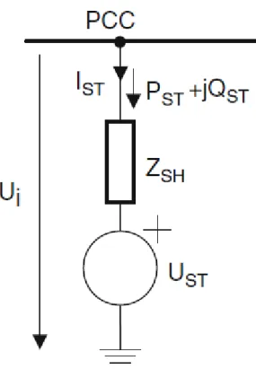
Fig. 3.34 Equivalent circuit of the Statcom
3.3.1 Mode of Operation
The VSC generates a voltage at the fundamental frequency Ust = Ust st with controllable voltage amplitude and phase. The VSC is connected to the grid Ui = Ui st through an inductive impedance, Zsh, that represents the coupling transformer and the connection filters, the equivalent circuit is as shown in Fig. 3.34.
The interchange of active and reactive power with the grid can be expressed as follows
Pst = U2i .gsh – Ui Ust [gsh. Cos(δi – δst) + bsh.sin(δi – δst)] (1) Qst = -U2i .bsh – Ui Ust [gsh. sin(δi – δst) - bsh.sin(δi – δst)] (2) Where Ysh = 1/Zsh = gsh + jbsh.
The capacity for injecting reactive power into the grid is limited by the maximum voltage and the maximum current allowed by the semiconductors, as shown in Fig. 3.35. The principle of operation of the VSC-based STATCOM depends on the control strategy for regulating the interchange of power between the converter and the grid and it depends also on the output AC voltage of the converter. If the magnitude of the voltage of the converter is equal to the voltage of the grid, Ust = Ui , the interchange of reactive power between the STATCOM and the grid is equal to zero.
In contrast, if the voltage of the converter is less that the grid voltage at the PCC, Ust < Ui, the STATCOM absorbs reactive power (draws lagging current).
However, if the STATCOM is controlled in such a way that the output voltage of the converter is higher than the PCC voltage, reactive power is injected into the grid [3].
In practice, it is also necessary to control the active power exchange of the STATCOM by regulating the phase angle δi st =δi - δst between the voltage at the VSC Ust = Ust st and the voltage at the PCC Ui = Ui st so that the VSC absorbs active power from the grid to maintain a constant voltage for the DC-link.
Fig. 3.35 Voltage–current characteristics of the STATCOM
3.3.2 Control Techniques
There are various control techniques, as detailed in [4] where the two listed below are the most typical:
• Voltage local control at the PCC voltage: In this control strategy, the purpose is to regulate the PCC voltage, Ui, so that it is maintained constant at its reference value Uiref. Mathematically, this condition is expressed as a restriction of operation:
Ui – Ui ref
= 0 (3) Reactive Power control at the PCC: In many situations, the STATCOM is required to inject reactive power into the grid according to the specifications of the TSO. This form of control can be applied, for example, when a coordinated control is required for FACTS devices and wind farms performing reactive power delivery to the entire grid. When this mode of operation is desired, it must be expressed as a restriction of operation as follows:
Qi – Qi ref
= 0 (4) 3.3.3 Restrictions of Operation
In a STATCOM the maximum reactive power that can be supplied to the grid depends on the maximum voltages and currents permitted by the power semi-conductors, so it is necessary to include the following internal restrictions: • The VSC output voltage must fall within the allowed limits of operation:
Ust;min Ust Ust;max (5) where Ust;min and Ust;max are the limiting values of the
minimum and maximum voltages allowed by the semiconductors, respectively.
• The current injected by the STATCOM, Ist , must be less than the maximum current allowed by the semiconductors, Ist;max:
I
stI
st;max(6)
Where:
I
st= | U
i– U
st| / Z
st(7)
• In contrast, it is necessary to include external restrictions of the grid voltage at the PCC. According to the specific regulations of the grid operator the grid voltage at the PCC must be maintained within certain allowed limits:
Ui;min Ui Ui;max (8)
III. STABILITY &CONTROL OF POWER SYSTEM
Power system stability is described as “the property of a power system that enables it to remain in a state of operating equilibrium under normal operating conditions and to regain an acceptable state of equilibrium after being subjected to a disturbance”. Instability occurs depending on the operation mode and the system configuration. Since power system is based on synchronous machines for generation of electrical power, the aspect of stability is influenced by the dynamics of generator rotor angles and power-angle relationships. Instability occurs also when a generator is disconnected due to a line fault, then the system becomes unstable due to voltage drop. The stability is not only an issue for the
generator synchronism but also on the control of voltage. Concerning the evaluation of stability of a power system is what happens when a transient disturbance occurs. The disturbance can be small or large. Small disturbance can be in form of load changes and the system must adjust itself to the changing conditions. The system must also be able to manage short-circuit on the transmission line, loss of a generator or load. In this chapter an understanding will be given of the different definitions and explanation to its occurrence. 3.4.1 The Stability Phenomena
Stability is a condition of equilibrium between opposing forces. During steady-state conditions there is equilibrium between the input mechanical torque and the output electrical torque for each machine. If the systems equilibrium is changed then this will result in acceleration or deceleration of the rotors of the machines according to the laws of motion of a rotating body. If one generator temporarily runs faster, the angular positions of its rotor relative to that of the slower will accelerate. The angular difference transfers part of the load from the slow machine to the fast machine. An increase in the angular separation is followed by decrease in the power transfer, this increases the angular separation further and that leads to instability in the system if some limits (generators) have been reached.
In the analysis the stability phenomena is separated in two categories, small-signal (small disturbance) and transient stability.
3.4.2 Small-signal
The ability of the power system to maintain synchronism under small disturbances, these disturbances can be small variations in loads and generation. The instability that may occur can be of two forms:
• Steady increase in rotor angle due to lack of sufficient synchronizing torque.
• Rotor oscillations of increasing amplitude due to lack of sufficient damping torque.
The disturbances depends on different factors such transmission strength and generators excitations control used. Small-signal stability is largely a problem of insufficient damping of the oscillations.
3.4.3 Transient stability
The ability of the power system to maintain synchronism under different transient disturbances. The instability can be one phase-to-ground, phase-to-phase-to-ground or three phase to ground and those can occur in transmission lines, transformers or bus.
3.4.4 Voltage Stability
The definition of the stability is: “The ability of a power system to maintain steady acceptable voltages at all buses in the system under normal operating conditions and after being subjected to a disturbance” [7]
The power system enters a state of voltage instability when a disturbance, increase in load demand or also changes in the system which can cause a voltage drop. The main factor for instability is that the power system cannot meet the demand for reactive power. The criterion for voltage stability is if the bus voltage magnitude increase the reactive power injection in the same bus is also increased. A system is unstable if one bus in the system voltage magnitude (V) decrease as the
reactive power injection (Q) (the same time) is increased. In shorter term the voltage is stable if V and Q are positive and unstable if V and Q are negative for at least in one bus. Voltage instability is essentially a local phenomenon but the consequence is that it can have a wide effect and suddenly a whole part can be involved.
Many factors can contribute to voltage instability: Strength of transmission system
Power transfer level Load characteristics
Generator reactive power capability limits
Characteristics of reactive power compensating devices 3.4.6 Models which interact on the voltage stability Loads: Loads characteristics can be critical in voltage stability analysis, it is important to check the voltage and frequency decency of the loads
Generators: It is necessary to take into account to the droop characteristics rather than to assume the zero droop. If line compensation is used it must be represented.
Static Var Systems: When a SVS is operating within the range the bus voltage can be seen as a slight of droop characteristics. It is more important to simulate when the SVS is operating at the reactive power limits.
3.4.7 The difference between voltage stability, transient stability
The terms voltage stability and transient stability are often used for the same aspect of power system stability phenomena. The definition for voltage stability was mentioned above (chapter 1.4), the definition for transient stability is “the ability of the power system to maintain synchronism when subjected to a severe disturbance” [7]. These two definitions should not be confused with actual electromagnetic “transient phenomena” [12]. The focus on the master thesis will be on voltage stability.
IV. SIMULATION &RESULT
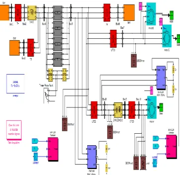
The system consists of a ten bus system as shown in Fig.4.1. The test system consists of three generators and five load bus. System consists of the ten buses which is connected to each other by three phase Pi section transmission line L1, L2, L3, L4 and L5 . Where L1 = 200 km, L2 = 200 km , L3 = 200km, L4 = 180km and L5 = 20km . There are three area in the system in which round rotor generators of different rated are used. The G1 = 5000 MVA/13.8 kV,G2 = 2200 MVA/13.8 kV,G3 = 1600 MVA/13.8 kV. In this power system different capacitive and resistive load are connected at different bus bars. The 868 Mvar & 300 Mvar capacitive load is connected near the bus 8 and 1500 Mvar is connected in bus 7 as well as the resistive and capacitive load are also connected with bus 10 of 300 Mvar.
Figure 4.1: Simulink Model Of Multi Grid Power System with Statcom
Figure 5.2: Voltage waveform of bus 1 to bus 5 with three phase fault in power system.
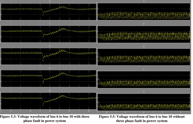
Figure 5.3: Voltage waveform of bus 6 to bus 10 with three phase fault in power system
Figure 5.4: Voltage waveform of bus 1 to bus 5 without three phase fault in power system
Figure 5.5: Voltage waveform of bus 6 to bus 10 without three phase fault in power system
Figure 5.6: Waveform at three phase fault in power system (i) voltage and current of line (ii) Reactive power (iii) Measure and reference voltage (iv)dc voltage of shunt controller.
Figure 5.7: Waveform at without three phase fault in power system (i) voltage and current of line (ii) Reactive power (iii) Measure and reference voltage (iv) DC voltage of shunt controller.
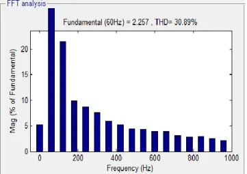
The given results shows that power system under the three phase fault condtion beconm partially unstable but after 3.5 sec the system comes in stable condition using statcom.the THD of the system 30.89 %.
Figure 5.8: Waveform of voltage at Statcom
Figure 5.9: THD graph of Power System
Figure 5.10: Current Waveform of Statcom V. CONCLUSION
The stability improvement of the multi-machine power system at three phase fault and without fault condition is investigated in this paper. When a three-phase fault is between bus 4 and bus 5 with STATCOM. Due to the fault, the system goes to in partially instability. But when three-phase fault not occurring between bus 4 and bus 5 with STATCOM, then the system shows the stability. i.e. the Statcom in power system at three phase fault condition get stable very fast compare without Statcom. The simulation of multi-machine (3-machine 10-bus) system with STATCOM FACTS controller has been done using MATLAB/Simulink software. This simulation can also be extended for multiple faults system and Complex multi-machine systems
REFERENCES
[1]. Anaya-Lara, E. Acha, "Modeling and analysis of custom power systems by PSCAD/EMTDC," IEEE Trans. Power Delivery, vol. 17, no . I, pp. 266-272, January 2002
[2]. Chun Li Ohrang Jiang, Z.Wang,“Design of rule based controller for STATCOM.” IEEE Industrial electronics society conference, Vol 1, Aachen, pp: 407-472, 1998. [3]. D.Bhanumurthy and Prashanth, “Power quality
improvement at distribution
level”,Proc.IJERA,vol.2,Issue.3,pp.970-975,Jun.2012 [4]. Dr.S.R.Paranjothi and A.Selvaraj “Voltage Sag
Mitigation on ASD”,
[5]. G. Radomski, “Modelling and modulation of voltage source converter”,13th Int. Power Electronics and Motion Control Conf. 1, 504–511 (2008).
[6]. J. J. Gutierrez, J. Ruiz, L. Leturiondo, and A. Lazkano, ―Flicker measurement system for wind turbine certification,” IEEE Trans. Instrum. Meas., vol. 58, no. 2, pp. 375–382, Feb. 2009.
[7]. K.R. Padiyar, ―FACTS Controllers in Power Transmission and Distribution”, New Age International (P) Limited, Publishers, 2002
[8]. Kolli Nageswar Rao, C. Hari Krishna, Kiran Kumar Kuthadi “ Implementation of D-STACTOM for Improvement of Power Quality in Radial Distribution System”, International Journal of Modern Engineering Research (IJMER), Vol. 2, Issue. 5, Sep.-Oct. 2012. [9]. M.Moadders, A.M.Gole,“Neural Network controlled
optimal PWM STATCOM.” IEEE Transaction on power delivery, Vol 14, No 2, pp: 481-488, April 1999. [10]. M. Tsili and S. Papathanassiou, ―A review of grid code
technology requirements for wind turbine,” Proc. IET Renew.power gen., vol. 3,pp. 308–332, 2009.
[11]. M.Madrigal, E.Acha., “Modelling OF Custom Power
Equipment Using Harmonics Domain
Twchniques”,IEEE 2009
[12]. Nicolas Lechevin and V.Rajagopalan, “Nonlinear control for STATCOM based on differential algebra,” IEEE power electronics specialist conference, Vol 1, Fukuoka, pp: 323-334, 1998.
[13]. Noramin Ismail, Wan Norainin Wan Abdullah “ Enhancement of Power Quality in Distribution System Using D-STATCOM” The 4th International Power Engineering and Optimization Conference (PEOCO2010), Shah Alam, Selangor, MALAYSIA. 23-24 June 2010,pp:418-224
[14]. R Chiumeo and C Gandolfi, “Simulations of a possible configuration of Premium Power Park”, International Conference on Renewable Energies and Power Quality (ICREPQ’10) Granada (Spain), 23-25th March, 2010. [15]. Ricardo Davalos Marin “Detailed Analysis of
Multi-pulse STATCOM”.
[16]. R.Meinski, R.Pawelek and I.Wasiak, “Shunt Compensation For Power Quality Improvement Using a STATCOM controller Modelling and Simulation”, IEEE Proce, Volume 151, No. 2, March 2008.
[17]. S. Heier, Grid Integration of Wind Energy Conversions. Hoboken, NJ: Wiley, 2007, pp. 256–259.
[18]. S.V. Ravi Kumar, S. Sivanagaraju, "Simualgion of D-Statcom and DVR in power system," ARPN jornal of engineering and applied science, vol. 2, no. 3, pp. 7-13, June 2007.
[19]. V.Malathi, “Power quality improvement of grid
interconnected distribution system FSS-LMS algorithm”, VOL.02, Issue.06, ISSN: 2319- 1163, Jun.2013.
BIOGRAPHY
Vineet Kumar Tripathi Belongs to UP received
his Bachelor of Technology degree from UPTU, Lucknow in 2010. He is pursuing his M.Tech in Electrical Engg. (Power Electronics) from SHIATS, Allahabad, UP-India. His field of interest includes
power electronics,
embedded system, programmable logic controller and electric drives.
Er. Vinay kumar Tripathi belongs to district
Allahabad of uttar pradesh. He received his bachelor of technology degree from UCER, allahabad in 2003. He obtained his M. Tech. in electrical eng. (control & instrumentation) from MNNIT, allahabad, Uttar pradesh in 2006 and pusuing Phd. from sam higginbottom institute of agriculture technology and sciences university (SHIATS), allahabad, up, india. He is having 10 years’ experience in teaching and presently working as asst. prof. in electrical engineering department, SSET, SHIATS, allahabad. His field of interest includes control and instrumentation, multiphase system, power quality and electric drive