R E S E A R C H
Open Access
Experimental analysis of bonded single lap joint
with flexible adhesive
Debora C Moreira and Luiz CS Nunes
** Correspondence:[email protected]
Laboratory of Opto-Mechanics (LOM/LMTA), Department of Mechanical Engineering/PGMEC, Universidade Federal Fluminense, UFF, Rua Passo da Patria 156, 24210-240 Niterói, RJ, Brazil
Abstract
Flexible adhesives play an important role in various applications. The possibility of bonding dissimilar substrates has generated wide interest in flexible adhesives. However, most of the theoretical and experimental investigations have focused on rigid epoxy adhesives. The purpose of this work is to investigate the mechanical behavior of a flexible adhesive joint in the overlap region. Aluminum adherends were used for single lap joint made with an adhesive characterized by high flexibility and large strains. The specimen was tested in tension. Full-field displacements of the overlap region were measured by the Digital Image Correlation method. A large shear strain of the order of 48% was observed. Small transverse deflections of the adherends were estimated. Also, it was observed that the shear strain distribution in the adhesive layer decreases at the overlap ends, which is different from previously reported results in the literature.
Keywords:Flexible adhesive; Single lap joint; Digital image correlation
Background
Knowledge of adhesion has a great importance for many bonded structures, mainly in automotive, aircraft and marine structures. A better understanding of the mechanical behavior of adhesively bonded joints necessitates a detailed investigation of the ad-herend and adhesive, as well as of the adad-herend-adhesive interface. The majority of stiff adhesives are employed in structural applications, while flexible adhesives are indicated for some particular cases. The use of flexible adhesives in engineering structures allows displacement between joints and can avoid structural failure. For instance, they may be used for bonding dissimilar substrates that present different coefficients of thermal expansion.
Several investigations have been concerned with mechanical behavior of bonded joints. Analytical models of adhesively bonded joints were established through the ef-forts of Volkersen [1], Goland and Reissner [2] and Hart-Smith [3]. An improvement to classical models of bonded lap joints has been proposed by Tsaiet al. [4]. Luo and Tong [5] presented a nonlinear analysis of single lap joints. A good literature review on theoretical models for bonded joints is summarized in the literature [6,7]. Recent publications show that bonded joints remain being extensively studied [8-10]. Full-field optical methods such as Moiré and Digital Image Correlation have been employed to determine strain fields of adhesively bonded joints [11-15].
lap joint (SLJ) made with an adhesive characterized by high flexibility and large strains. The specimen was tested under monotonic tensile load in quasi-static condition. For each load, an image of the overlap region of the specimen was captured. All images were processed using a homemade program based on the Digital Image Correlation. Thus, horizontal and vertical displacement fields were obtained.
Methods
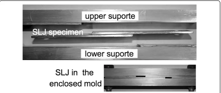
A single lap joint (SLJ) configuration was considered in the present study. The aluminum substrate surfaces received a treatment that consisted of abrading the over-lap region using a sandblasting machine and cleaning it with acetone before appli-cation of the adhesive. A flexible adhesive based on silane modified polymer, Cascola Flextec®FT 101, from Henkel (São Paulo, Brazil) was used. The mold illustrated in Figure 1 was used to make up the SLJ specimen. Using this mold, the final geometry of the SLJ specimen had an overlap joint of 33.5 mm, a joint width of 25.3 mm, and adhesive and adherends thicknesses of 0.15 mm and 2 mm, respectively. The elastic modulus of aluminum alloy plates was 68 GPa and the shear modulus of the adhesive was 0.52 MPa. It is important to remark that the adhesive is characterized by high flexibility and large strains [21,22].
The single lap joint was loaded in tension on an apparatus developed to ensure that one of the adherends moved parallel towards the applied load. The SLJ specimen was tested under monotonic tensile load in quasi-static condition and at room temperature, i.e., approximately 25°C. Figure 2 shows a close-up of the experimental arrangement
that was composed by the SLJ specimen fixed to the apparatus and a high resolution CCD camera with 1376x1024 pixels in the sensor array and a 10xZoom C-Mount lens.
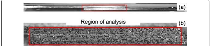
In the experimental procedure, the lateral surface of SLJ specimen was sprayed with black paint for obtaining a random speckle pattern. This process is essential to obtain the displacement fields using the optical method described below. The surface of over-lap region covered with random speckle pattern is illustrated in Figure 3. In this pic-ture, the rectangle drawn on the surface was chosen as the region of analysis. All specimen images in undeformed and deformed states associated with applied loads were captured with the CCD camera.
The displacement fields were measured using an optical method, which is known as Digital Image Correlation (DIC). This powerful optical-numerical method measures full-field surface displacements. DIC method is noncontact and relatively noninvasive. In the correlation procedure, small subsets from the undeformed image are compared to subsets from each of the deformed images in order to match maximum correlation between them and hence the displacements are determined. If the initial position of each subset is known, and its final position can be estimated, it is possible to compute the in-plane displacement fields designated by u(x,y) and v(x,y) associated with x- and y-coordinates. More information about this method can be found in the literature [23,24].
In the current work, a homemade DIC code based on a normalized cross-correlation function was used to obtain displacement fields with accuracy of the order of ±0.01 pixels. All acquired images were selected at 1314x199 pixel resolution. In order to per-form the matching process, reference and target subsets of 51x51 and 31x31 were
Figure 2Experimental setup.
homemade DIC code.
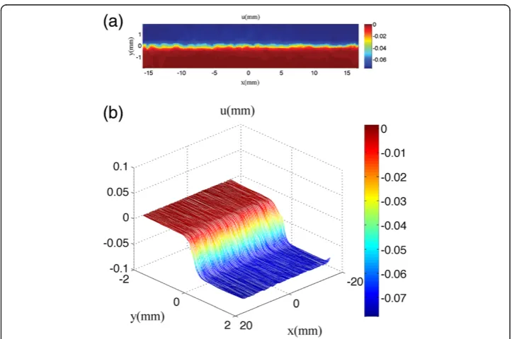
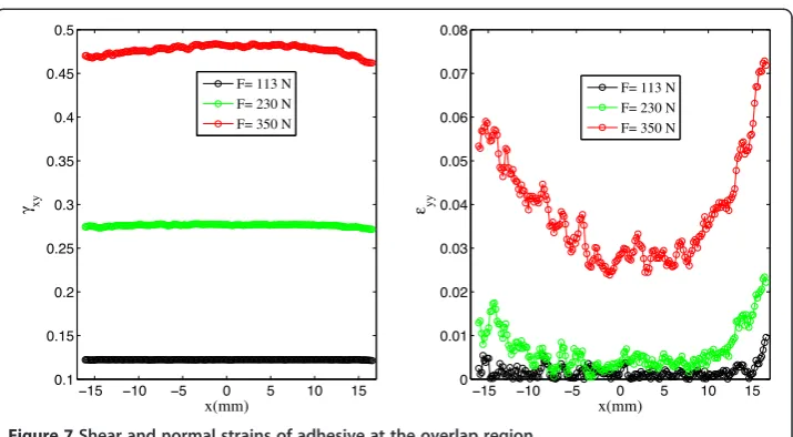
As previously described in Section 2, one end of the lower adherend was kept fixed to the apparatus while the other end was bonded to the upper adherend, in which the load was applied. It is important to remark that no type of failures was observed, considering the applied loads. As can be seen in Figure 4, there is no horizontal placement of the lower adherend, while the upper adherend presents an uniform dis-placement on the order of 0.07 mm and no significant deformation of the adherend is observed. Accordingly, the adhesive deforms in shear. Moreover, it should be noted that both lower and upper adherends present a rotation in the x-y plane, as shown in Figure 5. Neglecting rotations and considering only the initial thickness of the adhesive layer (0.15 mm), an angular distortion equal to 0.47 is achieved.
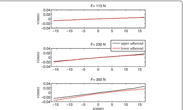
Besides the observed rotation in the joint, vertical displacements of lower and upper adherends at the edge of the overlap are different. This effect is related to the eccentric loading path of the SLJ that generates bending moments of the adherends. Due to the geometry and mechanical properties of adherends/adhesive, the effect of peel stress is more pronounced. To illustrate lower and upper adherends deflections, mean values of
the vertical displacement of each adherend along y-direction were taken. Figure 6 shows these mean values for lower and upper adherends, considering applied loads equal to 113, 230 and 350 N. It should be noted that, as the applied load increases, adherends deflections and the adhesive thickness at the edge of overlap increase as well. Nevertheless, this effect was not observed in cases with adherend stiffness much larger than the adhesive stiffness [25].
To analyze the effects in the joint for the current case, i.e. aluminum adherends and high flexible adhesive, values of shear and normal strain were investigated. Shear and
Figure 5Vertical displacement field of SLJ specimen at the overlap region: (a) color map and (b) surface plot.
−15 −10 −5 0 5 10 15
−0.04 −0.02 0 0.02 0.04
F= 113 N
v(mm)
−15 −10 −5 0 5 10 15
−0.04 −0.02 0 0.02 0.04
F= 230 N
v(mm)
−15 −10 −5 0 5 10 15
−0.04 −0.02 0 0.02 0.04
F= 350 N
x(mm)
v(mm)
upper adherend lower adherend
normal strains of the adhesive were obtained substituting the data illustrated in Figure 6 into the following definitions:
γxy¼uupper−ulower
h xð Þ and εyy¼
vupperð Þx −vlowerð Þx
hexp ð1Þ
with the adhesive thickness defined by h(x) =hexp+ [vupper(x)−vlower(x)]. Where uupper
and ulower,vupper and vlower denote the horizontal and vertical displacements of upper
and lower adherends, respectively. The initial adhesive thickness is denoted as hexp.
Figure7presents shear and normal strains in the adhesive layer along thex-coordinate for different applied loads. It can be clearly seen that shear strain decreases at the edge of the overlap, while there is an increase of normal strain.
It is well known that the eccentric load applied to a SLJ specimen generates a combined effect of bending moment and transverse force. The magnitude of each effect depends on adherend and adhesive stiffnesses, specimen geometry and loading condi-tions. In fact, shear is often associated with peeling forces. Works found in the litera-ture indicate that the shear strain in the adhesive layer increases at the edge of the
−15 −10 −5 0 5 10 15
0.1 0.15
x(mm) −15 −10 −5 0 5 10 15
0 0.01
x(mm)
Figure 7Shear and normal strains of adhesive at the overlap region.
overlap. In the present case, however, a different result was observed. It is important to emphasize that the adhesive stiffness used in this work is low in comparison to the adherends stiffness. Also, the adhesive is an elastomer, such that it is characterized by high flexibility and large deformation. Adams et al.[26] investigated two types of joint configuration that remove the stress concentration from the ends of the lap by profiling the adhesive layer. They used different rubbers to represent the adherends and adhe-sives and concluded that an adhesive joint could display a lower shear stress at the ends of the lap than in the middle, due to joint configuration. For that reason, the obtained results in the current work are suitable.
In order to facilitate the comprehension of this phenomenon, a schematic representa-tion of a single lap joint in a deformed configurarepresenta-tion is depicted in Figure 8. The dashed line denotes an adhesive deformation (angular distortion of γ2) that would be generated only by transverse load, while the other configuration is obtained if the bend-ing moment and peel effect are taken into account, which is placed with an angular dis-tortion ofγ1. In this case,γ2>γ1at the edges of the overlap, but they tend to the same value in the middle of the overlap.
Conclusions
The behavior of a single lap joint made with a flexible adhesive and aluminum adher-ends was experimentally investigated. The Digital Image Correlation method was employed for estimating the horizontal and vertical displacement fields at the overlap region of the single lap joint specimen. Vertical displacements associated to small adherend deflections were observed. Results indicate that the adhesive thickness was not equal along the horizontal coordinate. In fact, adhesive thickness was larger at the edge of the overlap due to eccentric loads and adhesive stiffness. Using the measured displacements, values of shear and normal strains in the adhesive layer were deter-mined. Contrary to results from previous works found in the literature, shear strain de-creased at the edge of the overlap. It is important to remark that a similar effect was observed by Adams et al. It should be noted that this study has examined only dis-placements and deformation. As a closing remark, one should mention that the current work might be used to support recent investigation based on finite element method. Moreover, analytical models of adhesively bonded joints may be developed assuming that the adhesive is a hyperelastic material.
Competing interests
The authors declare that they have no competing interests.
Authors' contributions
DCM carried out the manufacture the joints. DCM and LCSN tested the adhesive joints. LCSN drafted the manuscript. Both authors read and approved the final manuscript.
Acknowledgements
The financial support of Rio de Janeiro State Funding, FAPERJ, and Research and Teaching National Council, CNPq, are gratefully acknowledged.
Received: 27 August 2013 Accepted: 25 September 2013 Published: 29 January 2014
Reference
1. Volkersen O (1938) Die Nietkraftverleitung in zugbeanspruchten Nietverbindungen mit konstanten Laschenquerschnitten. Luftfahrtforschung 15:41–47
20:183–194
12. Moutrille MP, Derrien K, Baptiste D, Balandraud X, Grédiac M (2009) Through-thickness strain field measurement in a composite/aluminum adhesive joint. Compos Part A 40(8):985–996
13. Colavito KW, Das M, Hahs D, Gorman J, Madenci E, Smeltzer SS, III (2008) Digital Image Correlation for adhesive strains in Bonded Composite Lap Joints, 49th AIAA/ASME/ASCE/AHS/ASC Structures. Structural Dynamics, and Materials Conference, Schaumburg, IL. Paper No. 2008-1844
14. Colavito KW, Gorman J, Madenci E (2009) Refinements in Digital Image Correlation Technique to extract Adhesive Strains in Lap joints”. 50th AIAA/ASME/ASCE/AHS/ASC Structures, Structural Dynamics, and Materials Conference 4–7 May 2009, Palm Springs, California
15. Comer AJ, Katnam KB, Stanley WF, Young TM (2013) Characterising the behaviour of composite single lap bonded joints using digital image correlation. Int J Adhes Adhes 40:215–223
16. Banea M, da Silva LFM (2009) Mechanical characterization of flexible adhesives. J Adhes 85:261–285 17. Hoang-Ngoc CT, Paroissien E (2010) Simulation of single-lap bonded and hybrid (bolted/bonded) joints with
flexible adhesive. Int J Adhes Adhes 30:117–129
18. Lubowiecka I, Rodrí́guez M, Rodrí́guez E, Martí́nez D (2012) Experimentation, material modelling and simulation of bonded joints with a flexible adhesive. Int J Adhes Adhes 37:56–64
19. Banea MD, da Silva LFM (2010) Static and fatigue behaviour of room temperature vulcanizing silicone adhesives for high temperature aerospace applications. Mat.-wiss. u. Werkstofftech 41(5):325–335
20. Banea MD, da Silva LFM (2010) The effect of temperature on the mechanical properties of adhesives for the automotive industry. Proceedings of the Institution of Mechanical Engineers, Part L. J Mater Des Appl 224(2):51–62 21. Nunes LCS, Moreira DC (2013) Simple shear under large deformation: experimental and theoretical analyses.
Eur J Mech A Solids 42:315–322
22. Moreira DC, Nunes LCS (2013) Comparison of simple and pure shear for an incompressible isotropic hyperelastic material under large deformation. Polymer Test 32:240–248
23. Dally JW, Riley WF (2005) Experimental Stress Analysis, 4th edition. McGraw Hill. New York.
24. Sutton MA, Orteu JJ, Schreier HW (2009) Image Correlation for Shape. Motion and Deformation Measurements. Springer Science and Business Media LCC. New York.
25. Nunes LCS (2010) Shear modulus estimation of the polymer polydimethylsiloxane (PDMS) using digital image correlation. Mater Des 31:583–588
26. Adams RD, Chambers SH, Del Strother PJA, Peppiatt NA (1973) Rubber model for adhesive lap joints. J Strain Anal Eng Des 8:52–57
doi:10.1186/2196-4351-2-1
Cite this article as:Moreira and Nunes:Experimental analysis of bonded single lap joint with flexible adhesive.
Applied Adhesion Science20142:1.
Submit your manuscript to a
journal and benefi t from:
7Convenient online submission 7Rigorous peer review
7Immediate publication on acceptance 7Open access: articles freely available online 7High visibility within the fi eld
7Retaining the copyright to your article