Design and Development of a Brushless Direct
Current Motor
Chandan Das
1, Md. Barkat Ullah
2, M. Asaduzzaman
2, Syeed Ashraf
3, Humayun Kabir
1,
Md. Abdul Mannan Chwdhury
11
Department of Physics, Jahangirnagar University, Savar, Dhaka-1342, Bangladesh.
2
Dept. of Physics, Bangladesh Army University of Engineering & Technology , Qadirabad Cantonment, Natore, Bangladesh.
3
Bangladesh School Sohar, Sohar, Oman.
Abstract:The objective of the present work is to design and develop a brushless dc motor (BLDC).With the knowledge acquired from various magnetic designs and its power a motor has been built. The primary goal and focus is to be able to make a fully functioning motor. Once it is determined what type of material is to make the stator and other portions of the motor out of a reasonable size and power output is estimated. Using a general radial flux motor concept, the design is refined through calculations while keeping in mind the limitations of machining. This proved to be very difficult given the type of material that should to be machined. After many checks and calculations the final design was approved and parts was ordered. Using this radial flux motor design, all parts are manufactured using various machines; lathes, end mails, band saws, CNC mills, etc. from one single piece of bar stock steel. To power the designs stellaries, Texas Instrument, one phase BLDC motor controller is used. The motor has been modified to accommodate the Hall Effect sensors necessary to operate the controller. As will be shown throughout the research, many difficulties and frustrations are encountered during design and machining of the motor. It will be thoroughly explained through this research that the theories and practices in both magnetic design and electrical circuit theory can be manipulated into a device that changes electrical energy into mechanical energy.
Keywords:BLDC motor, Stator, Rotor, Hall sensor, Low Voltage Power Supply.
I. Introduction
The concept behind converting electrical energy into mechanical energy has been known since the late 1820’s when the first electric motor was successfully tested. These concepts over the years have been improved upon, but for the most part have remained the same. This applies to design of electric motors. Over the years there have been many upon many design changes to improve efficiency and output power, however the theories motor used today these basic and fundamental magnetic and electrical properties hold constant and are demonstrated through this research.
Electric motors are everywhere in world today. The world as we know it exists because of the electric motor. From the Hoover dam to our laptop computer there is an electric motor serving a purpose. From the beginning, motors have been used to improve the everyday life of the people on the Earth. They generate thousands upon thousands of kilowatts of electricity of power homes, factories, televisions, computers, microwaves, etc. They allow for one man to move thousands of pounds of material from one place to another replacing the need for twenty men to do the same job, just by using a simple hydraulic system with a motor. In today’s world electric motors power cars that can go from zero to sixty miles/hour in no more than a few seconds. Motors are essential to today’s way of life and make life easier as we know it.
As of today there are over 15 types of various DC and AC motors that all serve the purpose of converting electrical energy into mechanical energy or vice versa[1]. Of these many different one design in particular was chosen for this research. It displays the basic magnetic and electrical principles as mentioned earlier and is composed of a design that fits the overall goal this research.
The brushless direct current (BLDC) permanent magnet motor was chosen to demonstrate the theories and practices behinds electric motors. These particular types of motors are known for their high durability due to simplicity in design, and high RPM capabilities. BLDC motors have both small and large applications. For example, in every computer there is a hard drive. A hard drive consists of spinning disk that is powered by a small BLDC motor to rotate the hard drive disks at very fast speeds [2]. On the other hand with the newly developed hybrid cars coming out along with a small fuel efficient engine there are typically two or even four BLDC motors located on either the axel or each individual wheel [3]. Both of these motors are similar to this design in that they both run off of permanent magnets. This particular design is in between these two extreme (small, large) types of motors. The design although simple has been made extremely difficult when all aspects of a motor were to be taken into account and designed from scratch. The goal is a twelve volt, quarter horsepower design.
International Journal of Scientific Research and Engineering Development-– Volume 2 Issue 4, July – Aug 2019
Available at www.ijsred.com
ISSN : 2581-7175 ©IJSRED: All Rights are Reserved
Page 723
II. Design and Circuit Description
A. Specifications
Table: 1
The following table shows the Specifications of Designed Brushless DC Motor:
Serial
No Features Specifications 1 Main voltage 220 V, 50 Hz
2 Low voltage
power supply 12V DC
3 Temperature
range Up to 50 0
C
4 Output range 12V – 48V DC
5 Power 240 watt
6 Back up time Battery dependent
B. List of the Components
• Voltage Regulator: L7812
• Capacitors:
1. C1 = 1000 µF, 25V.
2. C2 = 0.10 µF, 25V.
3. C3 = 0.10 µF, 25V.
4. C4 = 0.10 µF, 25V.
5. C5 = 0.10 µF, 25V.
6. C6 = 0.47 µF, 25V. • Resistors:
1. R1 = 1.2KΩ, 0.25W.
2. R2 = 1.2KΩ, 0.25W.
3. R3 = 1Ω, 2W.
4. R4 = 1.2KΩ, 0.25W.
5. R5 = 1.2KΩ, 0.25W.
6. R6 = 1.2KΩ, 0.25W. • Diodes:
1. D1 = IN 4005, 5amp, 200V.
2. D2 = IN 4005, 5amp, 200V.
3. D3 = IN 4005, 5amp, 200V.
4. D4 = IN 4005, 5amp, 200V.
5. D5 = IN 4005, 5amp, 200V.
6. D6 = IN 4005, 5amp, 200V.
7. D7 = IN 4005, 5amp, 200V.
8. D8 = IN 4005, 5amp, 200V.
9. Z1 = 18V. • Transistors:
1. Q1 = C828, 0.50amp. • Transformer:
1. T1 = Step down. • Integrated circuit:
1. U1 = L6202.
2. U2 = H4007/400
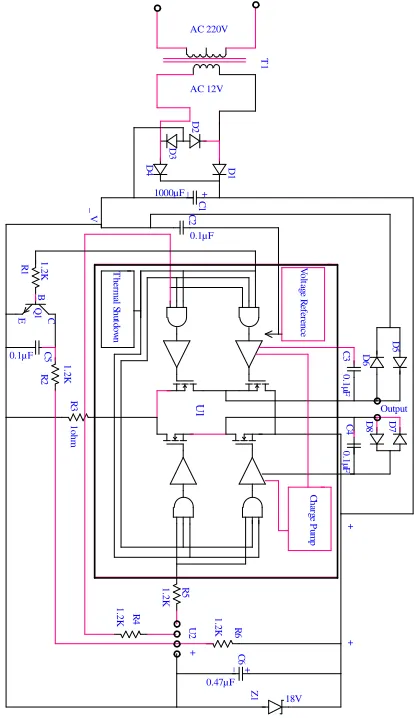
The complete circuit diagram of the designed BLDC motor is shown in Fig. 1. The descriptions of each part are furnished below:
C. Brushless DC (BLDC) Motor
A Brushless DC Motor (also known as a BLDC Motor), is a synchronous electric motor powered by a direct current. As the name implies, the Brushless DC Motor does not operate using brushes; rather it operates with a controller via electronic commutation [4].
Electrical equipment often has at least one motor used to rotate or displace an object from its initial position. There are a variety of motor types available in the market, including induction motors, servomotors, DC motors (brushed and
Fig. 1: Circuit diagram of Designed Brushless DC Motor.
V o lt ag e R ef er en ce D 1 D 2 D 3 D 4 + _ C 1 1000µF C 2 0.1µF C 3 0 .1 µF D 6 D 5 D 7 D 8 C 4 0 .1 µF T h er m al S h ut do w n R
1 1.2K
B
E Q1 C
brushless),etc. Depending upon the applicationrequirements, a particular motor can be selected. However, a current trend is that most new designs are moving towards Brushless DC motors, popularly known as BLDC motors [5].
D. Construction of Brushless DC Motor
A Brushless DC Motor (BLDC) motors have many similarities to AC induction motors and brushed DCmotors in terms of construction and working principles respectively. Like all other motors, BLDC motors also have a rotor and a stator [5].
E. Stator
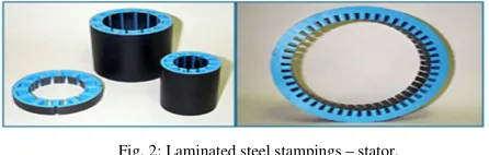
Similar to an Induction AC motor, the BLDC motor stator is made out of laminated steel stacked up to carry the windings[6]. Windings in a stator can be arranged in two patterns; i.e. a star pattern (Y) or delta pattern (∆). The major difference between the two patterns is that the Y pattern gives high torque at low RPM and the ∆ pattern gives low torque at low RPM. This is because in the ∆ configuration, half of the voltage is applied across the winding that is not driven, thus increasing losses and, in turn, efficiency and torque [5].
Fig. 2: Laminated steel stampings – stator.
Steel laminations in the stator can be slotted or slotless as shown in Fig.3. A slotless core has lower inductance, thus it can run at very high speeds. Because of the absence of teeth in the lamination stack, requirements for the cogging torque also go down, thus making them an ideal fit for low speeds too (when permanent magnets on rotor and tooth on the stator align with each other then, because of the interaction between the two, an undesirable cogging torque develops and causes ripples in speed [7]). The main disadvantage of a slotless core is higher cost because it requires more winding to compensate for the larger air gap.
Fig. 3: Slotted and Slotless motor.
Proper selection of the laminated steel and windings for the construction of stator are crucial to motor performance. An improper selection may lead to multiple problems during production, resulting in market delays and increased design costs [5].
F. Rotor
The rotor of a typical BLDC motor is made out of permanent magnets. Depending upon the application requirements, the number of poles in the rotor may vary [8].
Fig. 4: 4-pole and 8-pole permanent magnet rotor.
Another rotor parameter that impacts the maximum torque is the material used for the construction of permanent magnet; the higher the flux density of the material, the higher the torque [5].
G. Working Principles and Operation
The underlying principles for the working of a BLDC motor are the same as for a brushed DC motor; i.e., internal shaft position feedback. In case of a brushed DC motor, feedback is implemented using a mechanical commutator and brushes. With a in BLDC motor, it is achieved using multiple feedback sensors. The most commonly used sensors are hall sensors and optical encoders.
Hall sensors work on the hall-effect principle that a current-carrying conductor is exposed to the magnetic field, charge carriers experience a force based on the voltage developed across the two sides of the conductor [9]. If the direction of the magnetic field is reversed, the voltage developed will reverse as well. For Hall-effect sensors used in BLDC motors, whenever rotor magnetic poles (N or S) pass near the hall sensor, they generate a HIGH or LOW level signal, which can be used to determine the position of the shaft [5].
International Journal of Scientific Research and Engineering Development-– Volume 2 Issue 4, July – Aug 2019
Available at www.ijsred.com
ISSN : 2581-7175 ©IJSRED: All Rights are Reserved
Page 725
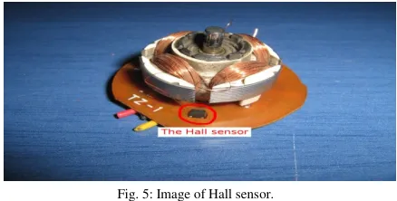
Fig. 5: Image of Hall sensor.The Hall sensor is this little component under the right electromagnet. When it senses the South Pole, it keeps the coils turned off. When the sensor senses no magnetic field (or could be also the South Pole), then it turns on the coils. The coils have both the same magnetic polarity which is north. So they pull the opposite pole and torque is then created [10].
If you put a probe to the Hall sensor and watch the signal, then you will discover that during a full rotation of the rotor, the Hall sensor is two times HIGH and two times LOW. The waveform on oscilloscope would be like this one:
Fig. 6: The waveform on oscilloscope.
Yet another great advantage for the brushless motors. This very signal that is used to control the coils can be used as is for measuring the speed of the motor! It can also be used to see if the motor is functional or not! Actually, this signal is exactly the one that comes out from the third wire from the PC fans that have 3 (or 4 wires)! These fans do not have any extra circuitry to measure the speed of the motor. They use the signal from the Hall sensor. Each revolution will generate 2 pulses. With a simple frequency measuring circuitry, someone can measure precisely the rpm of the motor [10].
H. Control of Brushless DC Motor
An electronic Brushless DC Controller (also known as a Driver, or Electronic Speed Controller), replaces the mechanical commutation system utilized by a Brush DC Motor, and is required by most Brushless DC Motors to operate. In a Brushless DC Motor controller, either a Hall Effect Sensor or Back EMF (Electromotive Force) is used to identify the position of the rotor. Understanding the orientation of the rotor is crucial to operating the Brushless DC Motor [5].
The Hall Effect uses three hall sensors within the Brushless DC Motor to help detect the position of the rotor.
This method is primarily used in speed detection, positioning, current sensing, and proximity switching. The magnetic field changes in response to the transducer that varies its output voltage. Feedback is created by directly returning a voltage, because the sensor operates as an analogue transducer. The distance between the Hall plate and a known magnetic field can be determined with a group of sensors, and the relative position of the magnet can be deduced. A Hall sensor can act as an on/off switch in a digital mode when combined with circuitry.
Back EMF, also known as the Counter Electromotive Force, is caused by a changing electromagnetic field. In a Brushless DC Motor, back EMF is a voltage that occurs where there is motion between the external magnetic field and the armature of the motor. In other words, the voltage is developed in an inductor by an alternating or pulsating current. The polarity of the voltage is constantly the reverse of the input voltage. This method is commonly used to measure the position and speed of the Brushless DC Motor indirectly, and due to the lack of Hall Sensors within the controller, these are often referred to as sensor less controllers [11].
I. Lifetime of a Brushless DC Motor
The Brushless DC Motor is often considered superior over the Brush DC Motor for its substantially longer lifespan. If run within the given specifications, the Brushless DC Motor can last over 20,000 operating hours based on bearing life. Running a Brushless DC Motor outside of its specifications shortens this lifespan [11].
J. Low Voltage Power Supply
In general, electronic circuits using tubes or transistors require a source of dc power. Dry cells and batteries are one form of dc source. They have the advantages of being portable and ripple free. However, their voltage are low; they need frequent replacement and also expensive as compared to conventional dc power supplies. In practice, dc power for electronic circuits can be obtained most conveniently from commercial ac lines (usually Vrms =220V) by using
rectifier-filter system. The process of converting ac voltage into dc voltage is called rectification.
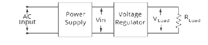
The rectifier circuit does not give pure dc voltage. Some ac ripple voltage rides on the dc voltage. When the load draws more current, the dc terminal voltage becomes less. Since the dc terminal voltage is affected significantly by the amount of load current this type of power supply is termed as unregulated power supply. An unregulated power supply consists of a transformer, a rectifier and filter. The block diagram of an unregulated power supply is shown in Fig.7.
AC line voltage
+
Output
-
Transformer
Fig. 7: Block diagram of an unregulated power supply.
There are three reasons for which such a simple system is not good enough for some applications. The first reasons is its poor regulation, (the output voltage is not constant as the load varies). The second reason is that dc output voltage varies with ac input. The other reason is that the dc output varies with temperature, particularly because semiconductor devices are used.
On the other hand, a dc power supply which maintains output constant irrespective of ac line voltage fluctuations or load variations is known as regulated power supply. An unregulated power supply can be converted in
power supply by adding a voltage regulating circuit to it. The block diagram of a regulated power supply is shown in Fig.8.
Fig. 8: Block diagram of a regulated power supply.
A voltage regulator can be designed with an op zener diode, resistors and few transistors but it is more convenient and quicker to use voltage regulator IC.
III. Results and Discussion The designed brushless DC motor circuit worked properly.
Detail result is as follows:
• Transformer:
Primary Input: 220V, 50Hz. Secondary Output: 12V, 50Hz.
• The Battery:
Input: 13.5V DC. Output: 12V DC.
• L6202 full Bridge driver: Input: 12V DC. Output: 16V DC.
• Current:
Input: 5amp. Output: 4.5amp.
• Inverter Circuit: Input: DC.
Output: AC, 100 KHz.
This research work was planned in a systematic way. The total activities were performed step by step. At first the whole
: Block diagram of an unregulated power supply.
There are three reasons for which such a simple system is applications. The first reasons is its poor regulation, (the output voltage is not constant as the load varies). The second reason is that dc output voltage varies with ac input. The other reason is that the dc output varies because semiconductor devices On the other hand, a dc power supply which maintains output constant irrespective of ac line voltage fluctuations or load variations is known as regulated power supply. An unregulated power supply can be converted into regulated power supply by adding a voltage regulating circuit to it. The block diagram of a regulated power supply is shown in
: Block diagram of a regulated power supply.
A voltage regulator can be designed with an op-amp a diode, resistors and few transistors but it is more convenient and quicker to use voltage regulator IC.
The designed brushless DC motor circuit worked
work was planned in a systematic way. The total activities were performed step by step. At first the whole
system was outlined in a block diagram and then circuits of different sections of the block were designed and tested. Finally all the circuits were arranged and connected properly and then tested.
Firstly, the power supply circuit was designed. A 220V AC supply was given to the circuit by a step down transformer and an output of approximately 12V DC was obtained at the output of voltage regulator L7812. There was a little voltage drop of about 1.5V across the circuit.
battery was connected to the charge circuit.
After that, to test it a 12V DC supply was applied and the output of this circuit approximately 16V DC was obtained by using a L6202 full Bridge driver. It was always difficult to obtain a pure DC output.
IV. Conclusion
Ultimately the complete engineering process of designing and building a permanent magnet BLDC motors has been completed and resulted in a success. Although output of the motor is not what the motor is designed for, the fact that the motor run shows a solid understanding of how an electric motor works. Also just as with many engineering research work the whole design takes twice as long to build at four times the price. Despite these facts the research work is well worth it and helps me to understand what th
engineering process is about and just how difficult it can be. The most disappointing portion of this research work is that the controller not functioning properly. The motor was not driven to its full potential due to the limitations of the controller. Looking back, despite what hardships may have been encountered when using a brushed system it may have been better choice. Using a brushed system
rid all of the “Safety Features” of an electronic controller. In a different kind of way it would have allowed more freedom as far as input power. Despite the issues with the con
as with any research there were plenty of difficulties and frustrations. However in the end it worked which was by far the most satisfying part of this research
designed well enough to work to some extent if not to its designed full extent.
To any future persons who would attempt any sort of research like this I would say, plan to spend lots and lots of time both troubleshooting and designing. In addition be prepared to spend a lot more money than anticipated. However the reward for a successful design will far out weight any hardships encountered during the process.
References
[1] Justin Damele (2011). “A Project on Brushless
and Built”. The Faculty of the Electrical Engineering Department California Polytechnic State University.
[2] Bird, John (2010); Electrical and Electronic Principles and
Technology. Routledge. pp. 63–
Retrieved 2013-03-17.
k diagram and then circuits of different sections of the block were designed and tested. Finally all the circuits were arranged and connected properly Firstly, the power supply circuit was designed. A 220V it by a step down transformer and an output of approximately 12V DC was obtained at the output of voltage regulator L7812. There was a little voltage drop of about 1.5V across the circuit. Then a 13.5V DC battery was connected to the charge circuit.
that, to test it a 12V DC supply was applied and the output of this circuit approximately 16V DC was obtained by using a L6202 full Bridge driver. It was always difficult to
Conclusion
Ultimately the complete engineering process of designing and building a permanent magnet BLDC motors has been completed and resulted in a success. Although output of the motor is not what the motor is designed for, the fact that the understanding of how an electric motor works. Also just as with many engineering research work the whole design takes twice as long to build at four times the price. Despite these facts the research work is well worth it and helps me to understand what the entire engineering process is about and just how difficult it can be. The most disappointing portion of this research work is that the controller not functioning properly. The motor was not driven to its full potential due to the limitations of the controller. Looking back, despite what hardships may have when using a brushed system it may have been better choice. Using a brushed systemwould havegotten rid all of the “Safety Features” of an electronic controller. In a d of way it would have allowed more freedom as far as input power. Despite the issues with the controller, just there were plenty of difficulties and frustrations. However in the end it worked which was by far of this research. The motor is at least designed well enough to work to some extent if not to its To any future persons who would attempt any sort of research like this I would say, plan to spend lots and lots of ting and designing. In addition be prepared to spend a lot more money than anticipated. However the reward for a successful design will far out weight any hardships encountered during the process.
A Project on Brushless DC Motor Design t”. The Faculty of the Electrical Engineering Department California Polytechnic State University.
International Journal of Scientific Research and Engineering Development-– Volume 2 Issue 4, July – Aug 2019
Available at www.ijsred.com
ISSN : 2581-7175 ©IJSRED: All Rights are Reserved
Page 727
[3] McLaren, P. G. (1984). Elementary Electric Power and Machines.pp. 68–74. ISBN 0-13-257601-5.
[4] Nailen, Richard (May 2005). "Why We Must Be Concerned With
Transformers". Electrical Apparatus.
[5] http://www.edn.com/design/sensors/4406682/
Brushless-DC-Motors---Part-I--Construction-and-Operating-Principles.
[6] Knowlton, A.E. (Ed.) (1949). Standard Handbook for Electrical Engineers (8th ed.). McGraw-Hill. p. 597.
[7] V. K. Mehta, “Principles of Electronics” S Chand and Company Ltd. Ramnagar, New Delhi 110055, P-141, 142, 364.
[8] Terman, Frederick E. (1955). Electronic and Radio Engineering (4th ed.). New York: McGraw-Hill. p. 15.
[9] Billings, Keith (1999). Switchmode Power Supply Handbook. McGraw-Hill. ISBN 0-07-006719-8.
[10] http://pcbheaven.com/wikipages/How_Brushless_Motors_Work/ [11] http://www.anaheimautomation.com/manuals/forms/