Intelligent Wireless Remote Control System Design for a Biped Robot
Chih-Hsuan Chen
1, Chih-Min Lin
1, 2,*1
Department of Electrical Engineering, Yuan Ze University, Taoyuan, Taiwan, ROC.
2
School of Informatics, Xiamen University, Xiamen, Fujian, China.
Received 30 July 2017; received in revised form 15 August 2017; accepted 26 August 2017
Abstract
This paper presents the design and implementation of an intelligent wireless remote control system for a biped
robot. A recurrent cerebellar model neural network (RCMNN) is introduced, then it is used for the walking control of a
biped robot. Furthermore, the remote communication module is designed for the remote control of a robot. Finally,
experimental results show that the developed system can achieve satisfactory control performance for the walking
control of a high-order nonlinear biped robot.
Keywords: biped robot, wireless remote control, cerebellar model neural network
1.
Introduction
Biped robots are a favorite topic in the field of robotics [1-3]. Many dynamics analysis and system control researches have
been presented for the biped robots [4-5]. In order to achieve adaptive control of a biped robot to face unknown environment, an
intelligent control algorithm will be proposed in this study .
Cerebellar model neural network (CMNN), first proposed by Albus, has been applied to control a robot manipulator [6].
CMNN has been applied for the control of complex dynamic systems due to its good generalizing capability and fast learning
property. In this paper, a recurrent CMNN (RCMNN) is introduced; then, an adaptive RCMNN-based control system is designed
for the walking control of a biped robot.
Remote control has been frequently used in a lot of auto -matic control systems. Recently, the wireless remote control robots
have been developed to dictate a biped robot to move according to the user’s commands . The proposed walking command
system can be applied to the remote medical robot, the exploration robot, the home security robot, and so on [7]. In the deve loped
biped robot, the Zigbee wireless communication has been designed for the remote communication between the monitoring
computer and the robot.
2.
Remote Control of the Biped Robot
In order to achieve remote wireless control, a wireless module is used for the communication between the robot and personal
computer (PC), as shown in Fig. 1. The wireless module is also used to monitor the motion of the robot. The Zigbee-100, which
has 2.4 GHz bandwidth, is designed for robot communication. This peer-to-peer communication module is not easy to be
interfered by other equipment or bands .
Fig. 1 Block diagram of remote communication robot
3.
Adaptive RCMNN-Based Control System
3.1. Cerebellar model neural network
A recurrent CMNN (RCMNN) is introduced as shown in Fig. 2. The basic functions of RCMNN are described as follows.
Input Space
Receptive-Field Space
Weight Memory Space
Association Memory Space Recurrent Unit
k
1
nk
Output Space
ko
w
-
kp
w
a
n p
1
p 1k
k na
k
ik
rrik TT
O n o
1 o s
I
s
A
s
R
s
W
s
O Input Space
Receptive-Field Space
Weight Memory Space
Association Memory Space Recurrent Unit
k
1
nk
Output Space
ko
w
-
kp
w
a
n p
1
p 1k
k na
k
ik
rrikik TT rrik TTT
O n o
1 o s
I
s
A
s
R
s
W
s
O
Fig. 2 Architecture of an RCMNN
(1) Input space Is: For a given a
a n T n p p
p
[ 1, 2,, ]
p , where na is the number of input state variables, each input state
variable pi is assumed to be quantized into ne discrete regions (called “neurons”) according to a given control space. (2) Association memory space As: Several elements, nf , can be accumulated as a “block”. In this space, each block performs
a receptive-field basis function, and the Gaussian function is adopted here as the receptive-field basis function, which can be represented as
2
2
( )
, 1, 2, rik ik
ik d
ik
p c
exp for k n
v
(1)where ik represents the output of the k -th receptive-field basis function for the i-th input with the mean cik and
variance vik .In addition, the input of this block can be represented as
) ( )
( )
(t p t r t T
prik i ikik (2)
where rik is the recurrent weight, and ik(tT)denotes the value of ik through delay time T. It is clear that the input of this block contains the memory term ik(tT), which stores the past information on the network and presents a dynamic mapping.
(3) Receptive-field space Rs: The k -th multidimensional receptive-field function is defined as
2
2
( )
( , , , ) , 1, 2,
a a
n n
rik ik
k k k k ik d
p c
exp for k n
v
p c v r (3)
Computer terminal peripheral circuits
Zigbee Zigbee
RS232
Wireless communicate
where a a
n T k n k k
k [c1 ,c2 ,,c ]
c , a
a
n T k n k k
k [v1 ,v2 ,,v ]
v and a
a
n T k n k k
k [r1,r2 ,,r ]
r . The multi-dimensional
receptive-field functions can be expressed in vector form as
T n k, , d] ,
, [ ) , , ,
(pcv r 1
Φ (4)
where ad
d
n n T T n T k
T
[c1, ,c , ,c ]
c , ad
d
n n T T n T k
T
[v1, ,v , ,v ]
v and ad
d
n n T T n T k
T
[r1 , ,r , ,r ]
r .
(4) Weight memory space Ws: Each location of Rs to a particular adjustable value in the weight memory space can be expressed as
11 1 1
1 1
1
[
,
,
,
,
]
o
d o o
o
d d d o
p n
n n k kp kn
p n
n n p n n
w
w
w
w
w
w
w
w
w
W
w
w
w
(5)where d
d
n T p n kp p
p[w1 ,,w ,w ]
w , and wkp denotes the connecting weight value of the p-th output associated with the k -th receptive-field.
(5) Output space Os: The output of RCMNN is the algebraic sum of the activated weights in the weight memory and is expressed as
nd
k k kp T
p
p w
o
1
Φ
w (6)
The outputs of CMNN can be expressed in a vector notation as
Φ W
o T T
n
p oO
o
o
[ 1,, ,, ] (7)
The architecture of RCMNN is designed to have the advantages of simple structure and dynamic characteristics. The role
of the recurrent loops is to consider the past value of the receptive-field basis function in the association memory space. Thus,
this RCMNN has dynamic characteristics.
3.2. Adaptive RCMNN-based control system
The biped robot system is highly nonlinear. To effectively control a biped robot, an adaptive RCMNN-based control is
introduced in this subsection. The configuration of the proposed adaptive RCMNN control system of the biped robot system is
illustrated in Fig. 3. There are two inputs for the adaptive RCMNN controller: first is the tracking error, wh ich is the difference
between the reference trajectory dm and actual trajectory d derived from accelerometer; and second is the angular velocity
obtained from gyroscope. The output of RCMNN is the control signal UHip, which adjusts the hip joint to achieve a stable posture. The robot needs this on-line adjusting technique to adjust its original trajectories as it encounters unexpected situations.
Another controller is the ZMP compensator, which is also an adaptive RCMNN for auto-tuning the reference trajectories. The
two inputs of the ZMP compensator are: the tracking error between the reference ZMP position PZMPref and the actual ZMP
position PZMP derived from (8); and the change of this ZMP tracking error. The out put of this RCMNN is the ZMP control effort
ZMP
u . By combining the pre-scheduled walking pattern Pwith the output of ZMP compensator uZMP , and after inverse
kinematics, the computed control torque 0 can be obtained for the biped robot. By adding the computed torque 0 with the hip
Fig. 3 Block diagram of the adaptive RCMNN control biped robot system
4.
Experimental Results
0 2 4 6 8 10 12 14 16
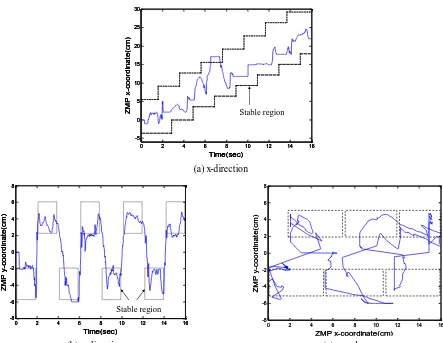
-5 0 5 10 15 20 25 30 Z M P x-co o rd in a te (cm ) Time(sec) Stable region (a)
0 2 4 6 8 10 12 14 16
-5 0 5 10 15 20 25 30 Z M P x-co o rd in a te (cm ) Time(sec) Stable region
0 2 4 6 8 10 12 14 16
-5 0 5 10 15 20 25 30 Z M P x-co o rd in a te (cm ) Time(sec) Stable region (a) (a) x-direction
0 2 4 6 8 10 12 14 16
-8 -6 -4 -2 0 2 4 6 8 Z M P y-co o rd in a te (cm ) Time(sec) Stable region (b)
0 2 4 6 8 10 12 14 16
-8 -6 -4 -2 0 2 4 6 8 Z M P y-co o rd in a te (cm ) Time(sec) Stable region
0 2 4 6 8 10 12 14 16
-8 -6 -4 -2 0 2 4 6 8 Z M P y-co o rd in a te (cm ) Time(sec) Stable region (b)
0 2 4 6 8 10 12 14 16
-8 -6 -4 -2 0 2 4 6 8 ZMP x-coordinate(cm) Z M P y-co o rd in a te (cm ) (c)
0 2 4 6 8 10 12 14 16
-8 -6 -4 -2 0 2 4 6 8 ZMP x-coordinate(cm) Z M P y-co o rd in a te (cm ) (c)
The RCMNN control system is accomplished by the proposed control system, whose structure is depicted in Fig. 2. The
RCMNN used here is characterized as ne 9 , nf 4 . The initial learning-rates are selected as ηzw0.01 and
. 001 . 0 zv zr
zm η η
η The initial values of weights are chosen as wkp0 and rik0. The initial values of parameters of means
and variances are chosen as vik22and [m mi1, i2,mi3,mi4,mi5,mi6,mi7,mi8] [ 49, 35, 21, 7, 7, 21, 35, 49] for all i and k . The
receptive-fields are selected to cover the input space{[35,35][35,35]} along each input dimension, respectively. These
parameters have been chosen through trials to achieve satisfactory con trol performance. The actual zero moment points (ZMPs)
are shown in Fig. 4. The experimental results show that the robot’s ZMP has been maintained within a stable region to achieve
stable walking.
5.
Conclusions
This paper has successfully developed and implemented an intelligent wireless remote control system for a
biped robot. The RCMNN-based control system is developed. This adaptive control system has been
successfully implemented on a biped robot system. The experimental results demonstrate the ability to achieve
satisfactory control performance for stable walking for a high nonlinear biped robot.
Acknowledgement
The support of the Nation Science Council of Republic of China under grant NSC 101-2221-E-155-026-MY3 is gratefully
acknowledged.
References
[1] Y. Sakagami, R. Watanabe, C. Aoyama, S. Matsunaga, N. Higaki, and K. Fujimura, “The intelligent ASIMO: System overview and integration,” IEEE/RSJ International Conf. on Intelligent Robots and Systems, September-October 2002, vol. 3, pp. 2478-2483.
[2] J. H. Kim and J. H. Oh, “Walking control of the humanoid platform KHR-1 based on torque feedback control,” Proc. IEEE
International Conf. on Robotics and Automation, April-May 2004, vol. 1, pp. 623-628, 2004.
[3] Y. D. Hong, Y. H. Kim, J. H. Han, J. K. Yoo, and J. H. Kim, “Evolutionary multiobjective footstep planning for humanoid robots,” IEEE Transactions on Systems, Man, and Cybernetics, Part C (Applications and Reviews), vol. 41, no. 4, pp. 520-532,
July 2011.
[4] K. Hosoda, T. Takuma, A. Nakamoto, and S. Hayashi, “Biped robot design powered by antagonistic pneumatic actuators for
multi-modal locomotion,” Robotics and Autonomous Systems, vol. 56, no. 1, pp. 46-53, January 2008.
[5] Y. S. Cha, , K. G. Kim, J. Y. Lee, J. J. Lee, M. J. Choi, M. H. Jeong, et al., “MAHRU-M: A mobile humanoid robot platform based on a dual-network control system and coordinated task execution,” Robotics and Autonomous Systems, vol. 59, no. 6, pp.
354-366, June 2011.
[6] J. S. Albus, “A new approach to manipulator control: The cerebellar model articulation controller (CMAC),” Journal of
Dynamic Systems, Measurement and Control, vol. 97, no. 3, pp. 220-227, September 1975.