SimuLTE-MEC: Extending SimuLTE for
Multi-Access Edge Computing
Giovanni Nardini, Antonio Virdis, Giovanni Stea and Angelo Buono
1 Dipartimento di Ingegneria dell’Informazione, University of Pisa, Italy[email protected], [email protected], [email protected], [email protected]
Abstract
Multi-access Edge Computing (MEC) is a novel paradigm to enrich current 4G and future 5G cellular networks by placing cloud-computing-based capabilities at the edge of the network. This will allow operators and service providers to endow the cellular network with enriched services. In this paper we describe the modeling and development of a MEC extension for the SimuLTE framework.
1
Introduction
The upcoming 5G era is foreseen to improve the performance of communication networks and to offer a wide range of new services to end users, by allowing different technologies, like Wi-Fi and cellular communications, to cooperate. Multi-access Edge Computing (MEC) represents one of these technologies, which promises to enable context-aware and real-time computing capabilities, by placing computational resources as close as possible to the users. The added value of MEC is the possibility to interact with the network elements to gather context information and to exploit them in order to optimize performance indicators, from both the user and the network operator standpoint. MEC is still in its early days, hence its possible benefits are currently being studied by the research community. Architectural choices, algorithms for optimizing both computational and network resources, solutions for minimizing latency and relocating computational resources are open research challenges [5]. In such context, system-level simulations are an effective solution that can be used for analyzing the performance of the MEC system and for prototyping new types of services.
In this paper, we present the modeling and the implementation of a MEC architecture for the OMNeT++ ecosystem. We integrate the MEC architecture within SimuLTE [3], which provides a complete framework for simulating LTE/LTE-Advanced networks. This way, one can evaluate the performance of MEC services with realistic conditions of the underlying network infrastructure. On one hand, our modeling choices aims at keeping the architecture as compliant as possible to the specifications defined by the European Telecommunications Standards Institute (ETSI) for MEC. On the other hand, we implemented the framework so that one can easily write its own MEC-based
Volume 56, 2018, Pages 35–42
service and plug it seamlessly within the model. The rest of the paper is organized as follows: Section 2 provides a brief overview of the MEC paradigm, including a high-level description of the framework proposed by ETSI. Section 3 describes the components of SimuLTE that comes into play when adding MEC. Section 4 describes the implementation of the MEC architecture within SimuLTE, whereas Section 5 shows the implementation of an exemplary MEC-based application and how to configure a simulation of such service. Section 6 concludes the paper.
2
Multi-access Edge Computing
With MEC, the edge of the communication network is enriched by nodes with large computation capabilities. Such nodes, typically called Mobile Edge (ME) servers or ME hosts, can be placed, for example, close to the radio base stations of the cellular network and can interact tightly with the latter in order to obtain valuable information on the status of the radio network and its users. This information can be exploited to offer new services that are context-aware and can take advantage of the reduced latency between the service and the end user, compared to, e.g., a cloud service. Examples of MEC-based use cases include computational offload for Internet-of-Things applications, smart transportation and dynamic content optimization.
Moreover, MEC is flexible, since ME applications run in a virtualized environment. This means that computational resources can be allocated on demand to users requesting a particular service or task. This allows the supervisor of the ME architecture (e.g., the network operator) to optimize the utilization of computational resources and possibly migrate a user’s application to another ME host.
2.1
ETSI MEC Architecture
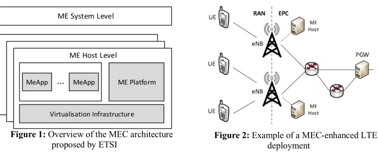
A framework for MEC is being standardized by the European Telecommunications Standards Institute (ETSI) [1]. According to that architecture, shown in Figure 1, functions are organized in two layers, namely the ME System Level and the ME Host Level.
The ME System Level is responsible for keeping a global vision about the status of all the ME Hosts in the system. In particular, it receives ME Application Instantiation requests from applications running at the user side (or from the operator or third-party applications). It first checks the requirements needed by the application, such as maximum communication latency, computational resources and availability of ME services. Then, it takes care of selecting – and instructing accordingly – the most suitable ME Host where the corresponding ME Application has to be instantiated, i.e. the ME Host that can satisfy the above requirements.
Figure 1: Overview of the MEC architecture proposed by ETSI
ME System Level
ME Host Level
ME Platform MeApp MeApp
Virtualisation Infrastructure
...
Within the ME Host, the ME Platform provides services defined in [2] that can be exploited by ME Applications. To cite some: the Smart Relocation Service handles migration of ME applications to other ME Hosts; the Radio Network Information Service (RNIS) is used to gather information from the network elements (e.g. number of users connected to a specific radio base station); the Bandwidth Manager defines the priority of data traffic destined to ME Applications within the ME Host; the Location Service provides information on the users’ position. The Virtualisation Infrastructure is the core of the ME Host, since it is responsible of running ME Applications as instances of virtual machines and allowing them to communicate both inside (e.g., with the services within the ME Platform) and outside the ME Host (e.g., with users’ local application).
2.2
MEC in LTE networks
MEC will be one of the key elements of the upcoming 5G ecosystem. From communication standpoint, the LTE-A technology (or, more likely, its evolution) will also be part of the 5G architecture. For this reason, MEC is foreseen to interact with the LTE-A as its communication counterpart.
LTE and LTE-A includes a Radio Access Network (RAN) part and an Evolved Packet Core (EPC) part. A simplified representation of an LTE-A network is shown in Figure 2. The LTE RAN is composed of eNodeBs (eNBs) and User Equipments (UEs). eNBs are the base stations handling radio cells, whereas the UEs are the cellular users that attach to the eNBs for communicating. The EPC side is an IP-based network, whose exit point is the Packet Data Network Gateway (PGW). The latter receives the packets destined to the UEs and forwards them to the correct eNB. This is accomplished by tunneling the communication using the GPRS Tunneling Protocol (GTP). At the eNB, the packet is de-tunneled and sent to the UE over the radio interface. Given the UEs’ mobility, a handover procedure is carried out when a UE changes its serving eNB due to, e.g., stronger received signal. In this case, the PGW has to redirect incoming traffic towards the new eNB, whereas on-the-fly packets can be steered using the X2 interface that connects neighboring eNBs directly.
In such context, ME hosts can be deployed anywhere in the EPC. However, it is likely that they will be placed close to the eNBs as depicted in Figure 2 so that a single ME host will be limited to the UEs connected to a small number of adjacent eNBs. As a result, service continuity must be maintained when a UE exploiting a MEC application moves far away from its ME host, possibly impairing the communication latency. Besides, it might be difficult to maintain context and radio awareness if the ME host is geographically remote. Thus, service migration should be guaranteed, e.g., when a UE performs a handover and moves into the geographical reach of another ME host.
3
Overview of SimuLTE
In this section, we provide a brief background on the main components of SimuLTE, with particular emphasis on the elements interacting with the MEC architecture.
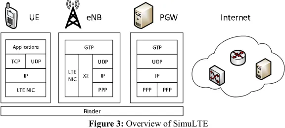
SimuLTE is a framework for system-level simulations of LTE and LTE-A cellular networks [3]. With reference to Figure 3, it provides complete models for both UEs and eNBs. The latter implement LTE radio capabilities thanks to the LTE Network Interface Card (NIC), which in turn includes one submodule for every layer of the LTE protocol stack, namely Packet Data Convergence Protocol (PDCP), Radio Link Control (RLC), MAC and PHY. Upper-layer protocols – from IP to applications – are instead provided by the INET framework. The X2 interface within the eNB allows it to communicate with neighboring eNBs, in order to enable, e.g., handover and interference-coordination algorithms.
point of the LTE network and provides routing between the eNBs and the rest of the Internet. A module, called Binder, is responsible to store network-wise information and all the modules of the LTE network (i.e., UEs, eNBs, PGW) can obtain such information by accessing it via direct method calls. Mobility of UEs can be simulated through the models provided by the INET framework. However, external tools can also be used to simulate the movement of UEs, e.g. simulating LTE-capable vehicles by integrating SimuLTE with Veins framework [4].
4
Modeling MEC within SimuLTE
We modeled a framework that allows a UE to dynamically request the initialization and the termination of one or more applications within a ME Host and to communicate with such applications so that a specific task is accomplished. We implemented the above architecture so as to allow one to develop its own ME Application and plug it seamlessly within SimuLTE. In this section, we first describe how we endowed SimuLTE with MEC capabilities. Then, we show the model of the communication flow between a UE and an application running inside the ME host.
4.1
Modeling the ME host
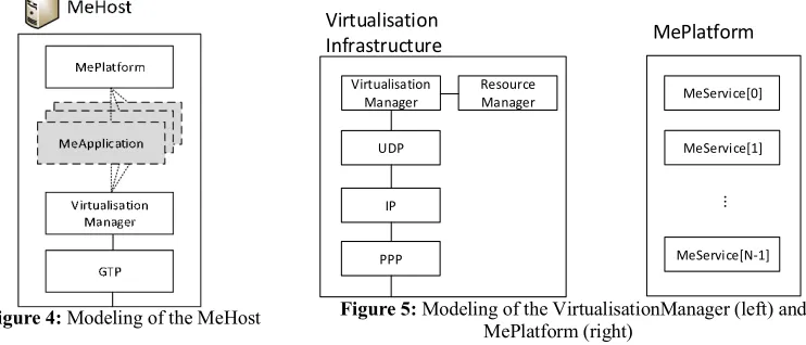
The main building block of our modeling is the MeHost, which is shown in Figure 4. The MeHost is a compound module including VirtualisationInfrastructure and MePlatform submodules, as per ETSI specifications. MeApplications are simple modules created on demand upon the reception of a request from UEs. They extend the IMEApp module interface, which the gates used to connect with the VirtualisationInfrastructure and, possibly, with the services exported by the MePlatform. module interface, which the gates used to connect with the VirtualisationInfrastructure and, possibly, with the services exported by the MePlatform.
Moreover, the MeHost includes a GTP module so that it can be placed anywhere in the EPC of the LTE network. Since every communication within the EPC is tunnelled using the GTP protocol (as described in Section 2.2), the GTP module provides the MEHost with the capabilities for encapsulating/decapsulating data packets within GTP packets.
Packets received from the EPC are decapsulated by the GTP and forwarded to the VirtualisationInfrastructure module. With reference to the left part of Figure 5, the latter includes the complete protocol stack, from the PPP interface to the transport protocol. On top of the latter, the VirtualisationManager is the module responsible for managing the life cycle of MeApplications: it handles UE requests for instantiation/termination of MeApplications and, once the latter are created, forwards data packets to the correct ones. To do this, it keeps a data structure called meAppMap that associates the requesting UE-side application to the gate where the MeApplication module is connected. The VirtualisationManager interacts with the ResourceManager, which keeps track of the
computational resources currently in use within the MEHost. In fact, we assume that each MEHost has a maximum amount of resources (RAM, storage and CPU) that can be allocated to MeApplications. Such amounts are configurable via NED/INI and can be different for each MEHost. When a request for creating a new MeApplication reaches the VirtualisationManager, the latter queries the ResourceManager to check whether the computational requirements of the application can be satisfied given the available resources. In the affirmative case, the ResourceManager marks the requested amount of resources as occupied, otherwise the application is not created. Allocated resources are then released when the MeApplication terminates (RAM, storage and CPU) that can be allocated to MeApplications. Such amounts are configurable via NED/INI and can be different for each MEHost. When a request for creating a new MeApplication reaches the VirtualisationManager, the latter queries the ResourceManager to check whether the computational requirements of the application can be satisfied given the available resources. In the affirmative case, the ResourceManager marks the requested amount of resources as occupied, otherwise the application is not created. Allocated resources are then released when the MeApplication terminates.
The MePlatform module(Figure 5, right)is instead the container of MeServices defined by [2]. In particular, it has an array of IMeService modules. An IMeService defines the module interface that needs to be implemented by every MeService. The number and the type of each MeService can be specified in the INI configuration file. Our implementation comes with a simplified version of the RNIS, used for recovering information from one or more eNBs of the LTE network (like UEs’ channel quality and bandwidth utilization).
4.2
Modeling the communication flow
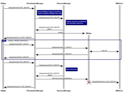
The life cycle of a MeApplication is controlled byMeAppPackets, which are exchanged between UEs and MeHosts and define the evolution of the status of the MeApplication. We model six types of packets, defined as follows. START_MEAPP and STOP_MEAPP are used by the UEs to request, respectively, initialization and termination of a MeApplication. Among the other fields, the MeAppPacket specifies the name of the MeApplication to be created, as well as its computational requirements. ACK_START_MEAPP and ACK_STOP_MEAPP provides the feedback to the UEs about the success of the request. Once the MeApplication is up and running, the UE can send INFO_UEAPP packets, which in turn can be answered by the MeApplication with INFO_MEAPP packets. Clearly, the type of data exchanged between the UE and the MeApplication depends on the type of application. To this aim, one can implement its own packet by inheriting the MeAppPacket structure and adding the required fields.
Figure 4: Modeling of the MeHost Figure 5: Modeling of the VirtualisationManager (left) and MePlatform (right)
PPP IP
Virtualisation Infrastructure
Virtualisation Manager
UDP
Resource
Manager MeService[0]
MePlatform
MeService[1]
MeService[N-1]
For the sake of concreteness, Figure 6 shows an example of the messages exchanged between a UE and the MeHost. First, the UE sends a START_MEAPP packet to the MeHost in order to activate a new MeApplication. The packet is parsed by the VirtualisationManager that, in turn, forwards the request to the ResourceManager. The latter allocates the requested resources and replies to the VirtualisationManager, which performs the instantiation of the MeApplication. In practice, it creates and initializes a new module for the MeApplication within the MeHost, connects its gates to both the VirtualisationInfrastructure and the MEPlatform, and adds an entry to the application map. If the creation is successful, a positive acknowledgement is transmitted to the UE.
Now, data packets flow between the UE and the MeApplication, through the VirtualisationManager. If necessary, the MeApplication can communicate with services within the MePlatform to carry out its operations. For example, it can contact the RNIS to collect information about the radio network.
When the UE has completed its task, it sends a STOP_MEAPP packet. The ResourceManager deallocates the resources, which are again available for other MeApplications, and the VirtualisationManager destroys the module representing the MeApplication. Again, an acknowledgement is transmitted to the UE.
5
Implementing and simulating a MEC-based service
In this section, we describe the implementation of a simple MEC-based application within the architecture described in the previous section. Then, we show how to configure a simulation that exploits such application.
We consider the use case of a vehicular environment, where drivers of vehicles are notified when entering a danger zone (DZ). In particular, a ME service running within a ME host keeps a map of geographical areas with potential dangers, e.g. roadworks, traffic jam, a slippery road etc. Each vehicle runs a local application that periodically reports its position to a ME application, representing the UE-side counterpart. Every time the ME application receives a position update from its corresponding vehicle, it queries the ME service and, if the reported position is within a DZ, sends back an alert to the vehicle. In order to implement such MEC-based service, we need to implement i) the UE-side application sending the vehicle position, ii) the ME application receiving the updates, iii) the ME service that checks when a vehicle has entered a DZ and iv) new types of MeAppPackets including the relevant information for the application. We call the first one UEWarningAlertApp and it has the traditional form of a UdpApp from INET. Its counterpart at the MeHost is the MEWarningAlertApp: it is a simple module extending the IMEApp interface, which receives packets from the UEWarningAlertApp and passes them to the MEWarningAlertService. The latter is implemented by inheriting the structure of the IMEService interface and creates a warning packet to be sent back to the MEWarningAlertService when an alert condition is verified. We also define WarningAlertPackets, which add the relevant fields to the base MeAppPacket for communicating the vehicles’ coordinates and a boolean flag that is set when an alert has to be signaled.
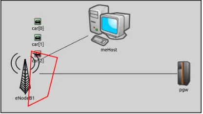
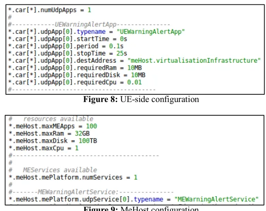
We now show the configuration of the scenario in Figure 7, which simulates three vehicles under the coverage of one eNB, moving along a road having a DZ at a specific point, denoted by the four-sided polygon. Vehicles’ mobility is simulated through Veins. Due to lack of space, details on how to configure network deployment and mobility are omitted and can be found in [4]. For each vehicle, called car[*], we define one UdpApp, whose typename is UEWarningAlertApp. As shown in the code snippet in Figure 8, the application is configured so as to send one packet to the MeHost every 100ms. Note that also the required resources can be specified within the INI file. On the other hand, the meHost module configuration (Figure 9) specifies the total available resources, the number of MeServices (one, in this case) and the type of the implemented service, namely the MEWarningAlertService. The DZ can be specified by setting the coordinates of the four edges within the MEWarningAlertService. The complete scenario configuration can be found on GitHub*.
* https://github.com/inet-framework/simulte
6
Conclusions
In this paper, we proposed a MEC extension for SimuLTE. The design has been carried out with the aim of allowing one user to easily enrich the model with new applications and services, while maintaining the compliance with the ETSI standards. After giving an overview of the MEC environment, we described the modeling of the MEC architecture within SimuLTE, with emphasis on the communication flow between the user and MEC entities. Finally, we presented the use case of a MEC service for assisted driving and described how to implement and configure the main simulation parameters for such scenario.
References
[1] ETSI GS MEC 003, “Mobile Edge Computing (MEC); Framework and reference architecture”, 2016-03
[2] ETSI GS MEC 002, “Mobile Edge Computing (MEC); Technical requirements”, 2016-03 [3] A. Virdis, G. Stea, G. Nardini, “Simulating LTE/LTE-Advanced Networks with SimuLTE”, in
Obaidat M.S., Kacprzyk J., Oren T., Filipe J. (eds) “Simulation and Modeling Methodologies, Technologies and Applications”, Springer, 2016
[4] G. Nardini, A. Virdis, G. Stea, “Simulating Cellular Communications in Vehicular Networks: Making SimuLTE Interoperable with Veins”, OMNeT++ Comm. Summit 2017, Bremen, DE [5] E. Ahmed, M.H. Rehmani, “Mobile Edge Computing: Opportunities, solutions and challenges”,
Elsevier Future Generation Computer Systems, vol.70, pp.59-63, May 2017 Figure 8: UE-side configuration