1.
Introduction
High demand for electricity is one of Iran‟s problems in the summer season. The main reason for this high demand is the utilization of intensive cooling equipment. In many power plants in Iran, gas turbines are used to supply the peak load.
Since gas turbines are complex systems that consume air directly, any factor that changes the conditions of the air surrounding the gas turbines will change the gas turbines‟ operation.
Gas turbines are considered as constant volume machines with a fixed rotational speed, and a constant volumetric flow rate of air passes through them. One of the impacts of an increase in the input temperature (i.e., the ambient air temperature) is a
decrease in air density. Increasing the temperature of the compressor‟s input air will lead to an increase in the compressor‟s work and a decrease in the turbines‟ productive power; as a result, for each Celsius increase in air temperature, a 0.6% to 0.9% decrease in net output power occurs [1, 2].
Both direct air cooling methods (such as an evaporation method) and indirect cooling methods (such as cooling the air by absorption or compression chillers) have been studied in several articles [3–7].
Evaporation cooling is generally carried out by spraying pressurized water (i.e., fog), evaporative cooling media, a spray inside the compressor, or a mixture of these methods. In the first-mentioned method, called the air washer method, by spraying water in the air that then evaporates, the air is cooled.
Thermo-economic analysis of implementing fog-based cooling system in
GE-F5 gas turbines (case study)
Seyed Mehdi Arabi
a, Mohammad aminy
a*, Hossein Ghadamian
a,
Hassan Ali Ozgoli
b, Behzad Ahmadi
aaDepartment of Energy, Materials & Energy Research Center (MERC), Tehran, Iran
bDepartment of Mechanical Engineering, Iranian Research Organization for Science and Technology (IROST), Tehran, Iran
Journal of Heat and Mass Transfer Research
Journal homepage: http://jhmtr.journals.semnan.ac.ir
A B S T R A C T
Presently, nearly 26,000 MW-worth of gas power plants and nearly 16,000 MW-worth of combined-cycle power plants have been installed in Iran. But their power output in the summer, when there is the most demand, reduces to a minimum compared to the winter season. The main reason for this is that gas turbines depend on the ambient air temperature. Since most of Iran has warm and dry climates, cooling down the input air to the compressor by means of water evaporation is the simplest method to solve this problem. This paper investigates the thermodynamic and economic behavior of a fog system on four units of GE-F5 turbines installed in the Shahid Zanbagh power plant. The results show that the application of this method causes an increase in the mass flow rate of the air input and reduces the work consumption of the compressor. It increases power production by 2.64 MW, and the required water for each unit is equal to 0.761 kg.s-1. Also, the payback time for this system was calculated to be less than 3 years.
© 2017 Published by Semnan University Press. All rights reserved. DOI: 10.22075/jhmtr.2017.1503.1100
PAPER INFO
History:
Submitted 2016-09-19
Revised 2017-05-13 Accepted 2017-05-19
Keywords:
Simulation;
Overall efficiency; Net present value; Off-design analysis; Evaporative cooling
Corresponding Author : Department of Energy, Materials & Energy Research Center (MERC), Tehran, Iran
In this method, if the water particles are oversized, the evaporation won‟t occur completely and some water drops will enter the compressor. In a fog-cooling system, filtered water is converted to fog-like particles by being passed through high-pressure nozzles (under 7–21 Pascals of pressure). The evaporation of these particles causes the air to cool in the gas turbine‟s entrance [8, 9].
In the second method, known as media, the air passes through wet surfaces. By the evaporation of a certain amount of water from these surfaces, the air cools. The cooling water‟s quality in this system can be lower than required in a fog-cooling system, but in this method, maximum evaporation cannot be achieved. The fog system has been under consideration since 1950 when Willcookes and Trutes [10] suggested that the injection of water into a compressor‟s input air would cause a decrease in the temperature of the compressor‟s output air and also reduce the work consumption of the compressor. In 1960, John and Howkins [11] analyzed the effects of spraying water into the air during the compression process on the compressor (i.e., wet compression).
In wet compression conditions which is the results of the wet compression cooling method, the goal is to get close to isothermal compression instead of adiabatic compression. This is done by spraying water drops into the compressor. The increase in cycle‟s net output power, reduction in the compressor‟s consumption work, and the decrease in pollution (NOx) are the results of air cooling with the humid compression method.
The efficiency of evaporative cooling highly depends on the environment‟s temperature and relative humidity. As the weather warms up and the relative humidity decreases, the efficiency of this method increases [2, 6, 12].
Bagnoli et al. [13] examined the effects of wet compression on the operation of a 7EA gas turbine. They found out that in comparison to standard conditions, gas turbines lose about 15% of their output power because of the increase of the air temperature.
Evaporative cooling systems require low capital and current cost, and they have an average repair cost compared to other cooling methods. They can also decrease NOx in the exhaust gasses of the gas unit [14]. Low operational efficiency and high water consumption are the main disadvantages of evaporative cooling systems. In addition, if the sprayed water drops don‟t evaporate before entering the compressor, they will harm the compressor‟s blades [15]. If we replace a fog system with wet
compression, the danger of the blades being damaged will be reduced [16–20]. The use of compression refrigeration cooling systems (i.e., compression chillers) [12, 21] and absorption refrigeration cooling systems (i.e., absorption chiller) [14] are the two
main methods of indirect cooling of the input air. In a refrigeration cooling system, which is a
no-contact cooler, air gets cold by passing over cold water coils. Chilled water flows in the cold coils, and air passing over these coils noticeably loses its heat. The chillers used in this method can be compression-based or absorption-compression-based. Also, the chiller can be used to produce water during non-peak- hours that can be saved for peak temperature hours. This method reduces the required equipment capacity for supplying needed refrigeration in peak heat conditions.
The ability to cool the air to a temperature lower than the wet-bulb temperature is one of the advantages of refrigeration coolers, and regardless of the humidity of the environment, a considerable amount of cooling can be attained. In order to prevent freezing, the air in the entrance of the compressor usually should not be lower than 5–8 degrees Celsius; so, in humid regions, these systems are preferred to evaporative cooling systems [14, 22]. Using a compression cooling system reduces the total efficiency of the thermodynamic cycle while cooling a compressor can increase the thermal efficiency of the compressor. Although using a compression cooling system causes an increase in net productive power, it also reduces thermal efficiency [23–25].
The results of Yong et al.‟s research [14], in which the economic potential of using a cooling system for combined cycle units was analyzed, the fog system‟s efficiency was considerable in the temperature range of 15 to 20 degrees Celsius cooling duty range, so fog cooling proposals despite of requiring less of an investment than chiller cooling systems, can overcome the cooling duty as it proposed.
In addition to what has already been said, other cooling systems have also been shown to improve the operation of gas units [15–20]. Farzaneh Gard et al. [15] and Zaki et al. [16] suggested using the reserved Brayton cycle to cool the input air and improve gas turbines‟ energy efficiency.
2.Fog-cooling system
As mentioned earlier, the required power to compress the inlet air is highly dependent on the ambient temperature. Based on thermodynamic relations, the power consumption of a compressor in relation to a unit mass of air can be obtained by the following:
Wcom= [CpT1 (P2/P1) (k-1/k)
-1]/ηc. (1)
According to this formula, by increasing T1 (the ambient air temperature), the energy consumed by the compressor will increase, which directly leads to a decrease in the net power at the turbine coupling.
Using evaporative cooling methods is one of the easiest ways to increase gas turbines‟ productive power. By increasing the relative humidity, or in other words, passing the air through a wet environment, the dry temperature of the air will noticeably decrease due to water evaporation.
One other evaporative cooling method is spraying water in the air (i.e., fog). Which is an adiabatic cooling process and occurs linearly with the constant wet-bulb temperature. This method works well, especially in environments with low relative humidity where the difference between wet and dry temperature is high. The working principles of evaporative systems are the absorption of latent heat from the air by water, thereby cooling the air. Accordingly, the evaporative cooling system‟s efficiency is defined based on the Equation (2), considering the amount of temperature difference:
. (2) The W and D indexes refer to wet and dry.
In a fog system, high-quality, demineralized water is passed through stainless steel nozzles with ruby orifices. This process is performed by high-pressure pumps in the range of 70 to 200 bar (mostly about 140 bars) in a high quality. The water is sprayed into the air in the form of little particles in sizes up to 100 microns. The reason why the water is transformed into small particles is to increase the water‟s surface area with the air and, as a result, speed up the water‟s evaporation rate.
Assuming adiabatic mixing, the energy gained by the sprayed water is balanced by the energy lost by the atmospheric air after cooling. Equation (3) identifies how this process occurs:
mw (hv3 – hw2) = ma (ha1 – ha3) + ω1 ma (hv1 – hv3), (3) where mw is the mass flow rate of cooling water,
hw2 is its enthalpy, ma is the mass flow rate of dry air,
ha3 - ha1 is the enthalpy change of dry air, ω1 is the
specific humidity (the humidity ratio) of inlet air (in kg of water per kg of dry air) and hv1 - hv3 is the enthalpy change of airborne water vapor after cooling.
The humidity ratio (ω1) can be specified directly or calculated by the Equation (4):
ω1=
, (4)
where pv1 is the partial pressure of water vapor, and P1 isthe total atmospheric pressure.
2.1. Fog system’s psychrometric analysis
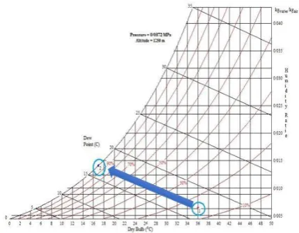
In the figure below, the operation of this system at 36°C (dry-bulb temperature) and 15% relative humidity is given in a psychrometric chart. As mentioned before, in a fog system, the air changes from the input condition to a 100% RH in a linearly continuous manner. According to Equation (1), the efficiency of a fog-cooling system is 100%, and unlike other cooling methods, such as media, the wet-bulb temperature is attainable. However, this system cannot pass the thermodynamic limit of the air‟s wet-bulb temperature, so the cooling potential of this method is limited [22].
According to the assumed input conditions and the application of the PsychroCalc software, the psychrometric conditions and parameters of system‟s output air are based on Table 1.
The advantages, such as its low installation, initiation, and running cost and the possibility of a fast installation, make using a fog system attractive. The high water requirement has caused some problems for using this system in low-water areas.
Since the efficiency of this system is a function of the air humidity, using these systems in humid regions would not be appropriately effective and would not lower the temperature noticeably; hence, the use of these systems in humid conditions does not have much economic justification.
The reason why a fog system‟s efficiency is higher than other evaporative cooling methods is the use of small water particles; therefore, determining the optimal diameter and the analyzing the dynamic behavior of water particles are very important.
Fig. 1. Psychrometric chart of fog in examined conditions Table 1. Output air psychrometric parameters
Parameter Unit Amount Dry-bulb temperature °C 17 Wet-bulb temperature °C 17 Relative humidity % 100 Humidity ratio kg water/kg dry Air 0.0141
Specific volume m3/kg 0.977
2.2. Experimental analysis of the fog system’s effectiveness
The fog spraying method has been used numerous for various power plants, which of them would be the proper case to gather data for the purpose of analysis.
2.2.1. Experiments from the effectiveness of fog system in Iran
In Iran, improving the capacity of gas turbines in the hot season began in 2000 by installing evaporative cooling system devices on Fiat turbines in the Rey gas power plant, and since then, they have been installed on several other power plants [26].
An example of one of the installed fog systems is in Yazd‟s combined-cycle power plant (C.C.P.P). Precise information on the fog system‟s operation in this power plant is provided in Table 2, which shows that the power plant has an ambient temperature of 38.3°C and a relative humidity of 7.4%. At the time of data collection, the capacity of this power plant was 1,000 MW. The fog system is installed on two GEF9 units with nominal capacities of 95 MW. These units are established at the altitude of 1,200 meters above sea level, and the local air pressure is 0.87 bar.
Table 2. The conditions before and after installing a fog system in the Yazd combined-cycle power plant
The experimental results show an increase in the production rate of about 12% and an increase in efficiency of about 0.9%. Other examples of a fog system application are described in Table 3.
Table 3. The effectiveness of example implementations of fog systems in Iran [26: Partly associated]
Location Gas unit type
Unit capacity
Increased power (MW) Shahid Rajaee
C.C.P.P. GE9171E 123.4 10.5 Montazer
ghaem C.C.P.P. GE9161E 123 8.5 Zahedan Power
Plant
Hitachi
5361 25 3.2 Bandar emam
Petrochemical ABB13D 120 8
2.2.2. The experimental case of using the fog system abroad
The fog system has been installed in other countries as well. One of the well-known companies that install and develop fog systems is Mee Fog. Table 4 shows some of the projects by this company and mentions the resulting increases in performance.
Table 4. The effects of some fog systems implemented abroad [27: Partly associated]
Location Gas unit type
Unit capacity
(MW)
Increased power (MW) Taweelah B, Abu
Dhabi GE9E 120 10 Ferrera Erbognone,
2.3. Identified fog systems for the investigated gas units
The investigated units are GEF5 single-shaft gas units. These units have horizontal shaft-driven compressors with 17 stages. The conditions considered for the design of the fog system were a temperature of 36°C and a relative humidity of 15% according to Yazd‟s climate.
The amount of mass flow contributed to the design conditions is 116.27 kg.s-1. Whereas, at off-design conditions, based on a diagram at the manufacturer‟s documentation and according to available environment‟s dry temperature, a correction factor of 85% should be considered for the purpose of mass flow calculations. In the investigated conditions, the input air‟s mass flow was 98.83 kg.s-1
. It should be noted that gas turbines are rotary machines with a constant flow rate at a constant rotation per minute, and their mass flow rate doesn‟t change in various environmental conditions.
2.4. Increase in production rate due to the application of fog system
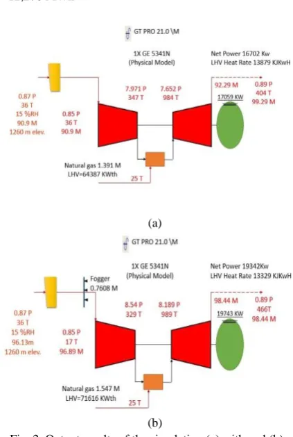
In order to calculate the production increase of the GEF5 units in the investigated conditions, the units‟ behavior was simulated in the Thermoflow software.
The output results of the software before and after implementing the fog system are shown in Figure 2. In this simulation, the type of fog system was selected “under spray fogging” and the particle sizes were also selected “fine”. Also, the effectiveness of the fog system was considered to be 100%. This means that the fog system‟s output temperature was considered equal to the wet-bulb temperature.
Based on the simulation results, the increase in production was 2.64 MW, and the water needed for the fog system was 0.7608 kg.s-1 per unit.
Regarding Yazd‟s climate, the hot season, in which the fog system was applied, lasts about 5 months from mid-May to mid-October and is a relevant factor for 7.5 hours daily, from 10:00 to 17:30. Based on the results, on average, the amount of power increase due to the implementation of a fog system is 2.6 MW.
Accordingly, the total surplus electrical energy that is produced in a period is calculated based on Equation (5), as follows:
Surplus produced power = (No. of units) × (increased power) × (daily working hours) × (days in a month) × (No. of the month)
Surplus produced power = 4 × 2.64 × 7.5 × 31 × 5 (5)
= 12,276 MWh
(a)
(b)
Fig. 2. Output results of the simulation (a) with and (b) without the fog system
Based on simulation results, the amount of increase in fuel consumption because of the fog system is 156 lit.s-1 per unit.
3. Economic analysis of the fog system
In an economic analysis of fog systems, the capital costs, current costs, earnings due to the use of the system, interest rate, etc. should be considered.
3.1. Capital costs
This cost includes designing, purchasing, installing, and initiating the fog system (e.g., implementing a skid pump complex and piping inside the nozzle ducts). Also, because this system uses purified water, it includes the cost of constructing a water purification building and reverse osmosis (RO) facilities.
3.2. Current costs
3.2.1. Extra fuel cost due to the power increase
According to the simulation results, the amount of unit fuel consumption without the fog system at 16.702 MW production is 1.391 kg.s-1 of natural gas with a fuel consumption rate of 299.82 kg.MWh-1.
The results of the simulation with the fog system show that the unit consumes 1.547 kg.s-1 of natural gas for 19.342 MW of production. A comparison of the results shows that the unit‟s fuel consumption with the fog system for the additional productive megawatts is about 49% less than a unit‟s level for producing megawatts in its normal condition. The amount of additional fuel consumed by the fog system is 561.5 kg.h-1, and, considering the consumed gas in a working pressure of 8.45 kg.m-3, a volume of 66.45 m3.h-1 of gas will be consumed.
The price of each cubic meter of consumed gas in a power plant is 720 rials. Therefore, the cost of the consumed gas is 47,844 rials per hour and 556,186,50 rials per period.
3.2.2. The cost of repairs, maintenance, and utilization
The cost of implementing a fog system contains repairs and maintenance of the skid pump complex, water purifier, the nozzles, and filters; fixing any leaks; and possibly replacing any defective parts. The fog system works automatically and does not require a resident technician. In the water purifying unit, considering the requirement for chemical injections and the system‟s sensitivity, a technician is required. Totally, the repairs, maintenance, and utilization costs of a fog system for 4 units equals 2% of the capital cost according to the experimental information supplied by Ali Behdashti et al. [28].
3.2.3. Consumed electricity cost
The fog system‟s electricity consumption is related to the skid pump and RO system pump. Considering the required amount of flow and pressure and the experimental data from similar power plants, the consumed power of a skid pump complex is 15 kW, and the unit‟s electricity consumption is 3 kW for each cubic meter of demineralized water [25]. Therefore, the amount of consumed electricity in a period of 4 units is 107,957/376 kWh, and the consumed electricity cost for a period (calculated as 440 rials.kWh-1) is 47,501,245/44 rials.
3.2.4. Consumed water cost of a fog system
According to the simulation results, a fog system needs 0.7608 kg.s-1 of water. In a utilization period, the total amount of demineralized water needed for 4 units of a fog system is 12,735,792 kg. In the RO purifying unit, considering the input water quality, each cubic meter of demineralized water will require 1.5 m3 of input water. Therefore, the total required water for 4 units is 19,103.63 m3. The fixed price of each cubic meter of water for this power plant is 1,200 rials. Therefore, the cost of consumed raw water during a period of utilization will be 22,924,425.6 rials.
3.2.5. Production halting damage
Installing the fog system equipment on a unit takes less than a week. It should, therefore, be planned in one of the maintenance periods so that there won‟t be any need to stop the production. Hence, no costs were considered in this section.
3.3. Earnings from the increase in production
Excess electricity produced by using the fog system occurs in peak hours, and the selling price of each kWh electricity during peak hours is 440 rials. Therefore, the earnings made from 4 units in a period of utilization are 5,401,440,000 rials.
3.4. Calculating the return on investment
For calculating the return on investment, the net present value method was used, which is one of the standard methods for analyzing economic plans. Based on the occurrence time, the earning or costs will be converted to the current rate, so the time value of cost and income is considered in the cash flow. In the net present value method, costs and revenues are discounted depending on available circumstances with appropriate interest rate according to the Equation (6):
. (6)
In this equation
t
is the time expense or
income occurrence,
I
is the interest rate, and
R
tis
the quantitative value of income or expense
based on cash flow.
rials, and the earnings of each period is
5,401,440,000 rials. If the annual interest rate is
15% (including annual inflation rate, interest
rate, and risk rate), and the lifespan of the
equipment is considered to be 10 years, the
calculation results are presented in Table 5.
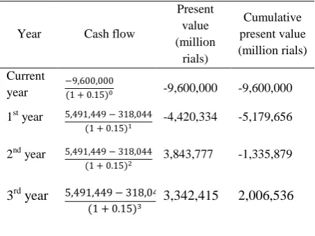
The last row in the last column of Table 5 is
the current net present value (NPV) of the
project. Because it is positive, it shows that
performing the project is affordable and
economic, and the return on investment is less
than 3 years.
Table 5. NPV (net present value) calculation
Year Cash flow
Present value (million
rials)
Cumulative present value (million rials) Current
year
-9,600,000 -9,600,000
1st year
-4,420,334 -5,179,656
2nd year
3,843,777 -1,335,879
3rd year
3,342,415 2,006,536
4. Conclusion
According to Yazd‟s climate, the utilization of a fog system was considered from May to mid-October (5 months) and for 7.5 hours daily. The design conditions of the fog system were considered to be at a temperature of 36°C and a relative humidity of 15%.
Analyzing the results shows that the application of a fog system in order to cool the input air of Shahid Zanbaqh gas power plant‟s GEF5 units in the hot and dry weather of Yazd would cause an increase in the input air mass flow rate and a decrease in the compressor‟s work consumption in the utilization period, such that the amount of increase in the productive MWs of each unit would be 2.64 MW, assuming a relative humidity of 100% of the system‟s output air. The amount of water that the fog system needs for each unit is 0.7608 kg.s-1. Also, the calculated return on investment indicates an investment in a fog system would make returns in less than 3 years.
Acknowledgments
This work was financially supported by the
cooperation of the Materials and Energy Research
Center (MERC) and the Tak-Niroo company for the
purpose of scientific development. We acknowledge
them for their support.
Nomenclature
Cp Specific heat at constant pressure (kJ/kg.K)
h Enthalpy (kJ/kg)
i Interest rate
k Specific heat ratio
NPV Net present value
P Pressure (pa)
Pv Partial pressure of water (pa)
RH Relative Humidity
Rt Quantitative value of income
t Time
TD Dry-bulb temperature (K)
TW Wet-bulb temperature (K)
Wcom Compressor‟s power consumption (kW)
ηc Efficiency of the compressor
ω Specific humidity
References
[1]. H.A. Ozgoli, H. Ghadamian, A.A. Hamidi, „„Modeling SOFC & GT Integrated-Cycle Power System with Energy Consumption Minimizing Target to Improve Comprehensive cycle Performance (Applied in pulp and paper, case studied)‟‟, GSTF Journal of Engineering Technology (JET), 1(1), 1-6, (2014).
[2]. H. Ghadamian, A.A. Hamidi, H. Farzaneh, H.A. Ozgoli, „„Thermo-economic analysis of absorption air cooling system for pressurized solid oxide fuel cell/gas turbine cycle‟‟, Journal of Renewable and Sustainable Energy, 4(4), 043115 1- 043115 13, (2012).
[4]. C.R. Cortes, D.E. Willems, „„Gas turbine inlet air cooling techniques: an overview of current technologies‟‟, POWER-GEN, Las Vegas, Nevada, USA, (2003).
[5]. T. Wang, X. Li, V. Pinninti, „„Simulation of mist transport for gas turbine inlet air cooling‟‟, Numerical Heat Transfer, Part A: Applications, 53(10), 1013-1036, (2008).
[6]. M. Ameri, H. Nabati, A. Keshtgar, „„Gas turbine power augmentation using fog inlet air-cooling system‟‟, ASME 7th Biennial Conference on Engineering Systems Design and Analysis. American Society of Mechanical Engineers, 73-78, (2004).
[7]. M. Ameri, H.R. Shahbazian, M. Nabizadeh, „„Comparison of evaporative inlet air cooling systems to enhance the gas turbine generated power‟‟, International Journal of Energy Research, 31(15), 1483-1503, (2007).
[8]. H.A. Ozgoli, H. Ghadamian, H. Farzaneh, „„Energy efficiency improvement analysis considering environmental aspects in regard to biomass gasification PSOFC/GT Power Generation System‟‟, Procedia Environmental Sciences, 17, 831-841, (2013).
[9]. H.A. Ozgoli, H. Ghadamian, R. Roshandel, M. Moghadasi, „„Alternative Biomass Fuels Consideration Exergy and Power Analysis for Hybrid System Includes PSOFC and GT Integration‟‟, Energy Sources, Part A: Recovery, Utilization, and Environmental Effects, 37(18), 1962-1970, (2015).
[10]. E.C. Wilcox, A.M. Trout, „„Analysis of thrust augmentation of turbojet engines by water injection at compressor inlet including charts for calculating compression processes with water injection‟‟, NASA: National advisory committee for aeronautics, 97-116, (1951).
[11]. S. Sanaye, H. Rezazadeh, M. Aghazeynali, M. Samadi, D. Mehranian, M.K. Ahangaran, „„Effects of inlet fogging and wet compression on gas turbine performance‟‟, ASME Turbo Expo 2006: Power for Land, Sea and Air, American Society of Mechanical Engineers, 769-776, (2006).
[12]. M.M. Alhazmy, R.K. Jassim, G.M. Zaki, „„Performance enhancement of gas turbines by inlet air-cooling in hot and humid climates‟‟, International journal of energy research, 30(10), 777-797, (2006).
[13]. M. Bagnoli, M. Bianchi, F. Melino, A. Peretto, P.R. Spina, S. Ingistov, R.K. Bhargava, „„Application of a Computational Code to Simulate Interstage Injection Effects on GE Frame 7EA Gas Turbine‟‟, Journal of
Engineering for Gas Turbines and Power, 130(1), 012001 1-012001 10, (2008).
[14]. C. Yang, Z. Yang, R. Cai, „„Analytical method for evaluation of gas turbine inlet air cooling in combined cycle power plant‟‟, Applied Energy, 86(6), 848-856, (2009).
[15]. M. Farzaneh-Gord, M. Deymi-Dashtebayaz, „„A new approach for enhancing performance of a gas turbine (case study: Khangiran refinery)‟‟, Applied Energy, 86(12), 2750-2759, (2009).
[16]. G.M. Zaki, R.K. Jassim, M.M. Alhazmy, „„Brayton refrigeration cycle for gas turbine inlet air cooling‟‟, International Journal of Energy Research, 31(13), 1292-1306, (2007).
[17].R.K. Jassim, G.M. Zaki, M.M. Alhazmy, „„Energy and exergy analysis of reverse Brayton refrigerator for Gas Turbine power boosting‟‟, International Journal of Exergy, 6(2), 143-165, (2009).
[18]. J.R. Khan, W.E. Lear, S.A. Sherif, J.F. Crittenden, „„Performance of a novel combined cooling and power gas turbine with water harvesting‟‟, Journal of Engineering for Gas Turbines and Power, 130(4), 041702 1-041702 10, (2008).
[19]. D.C. Erickson, I. Kyung, G. Anand, E.E. Makar, „„Aqua absorption turbine inlet cooler‟‟, ASME 2003 International Mechanical Engineering Congress and Exposition, American Society of Mechanical Engineers, 49-56, (2003).
[20].D.C. Erickson, „„Power Fogger Cycle‟‟, ASHRAE transactions, 111(2), 551-554, (2005).
[21]. R. Gareta, L.M. Romeo, A. Gil, „„Methodology for the economic evaluation of gas turbine air cooling systems in combined cycle applications‟‟, Energy, 29(11), 1805-1818, (2004).
[22]. M. Chaker, C.B. Meher-Homji, T. Mee, A. Nicolson, „„Inlet Fogging of Gas Turbine Engines: Detailed Climatic Analysis of Gas Turbine Evaporative Cooling Potential‟‟, ASME Turbo Expo 2001: Power for Land, Sea and Air, American Society of Mechanical Engineers, 1-16, (2001).
[23]. M.M. Alhazmy, Y.S.H. Najjar, „„Augmentation of gas turbine performance using air coolers‟‟, Applied Thermal Engineering, 24(2), 415-429, (2004).
[25]. C.B. Meher-Homji, T.R. Mee, „„Gas turbine power augmentation by fogging of inlet air‟‟, Proceedings of the 28th Turbomachinery Symposium, 93-114, (1999).
[26]. J.A. Sadri, P. Hooshmand, „„Enhancing efficiency of combined cycle Gas Power Plant Using Fog‟‟, Journal of Basic and applied scientific Research, 2(1), 10-16, (2012).
[27]. Mee industries inc., „„Gas turbine inlet air cooling and wet Compression‟‟, (2015).