Please cite this article as: E. Poursaeidi, K. Torkashvand, M. Mohammadi, Air Plasma Sprayed Bond Coat Oxidation Behavior and its Resistance to Isothermal and Thermal Shock Loading, International Journal of Engineering (IJE), IJE TRANSACTIONS C: Aspects Vol. 32, No. 6, (June 2019) 872-876
International Journal of Engineering
J o u r n a l H o m e p a g e : w w w . i j e . i rAir Plasma Sprayed Bond Coat Oxidation Behavior and its Resistance to Isothermal
and Thermal Shock Loading
E. Poursaeidi*, K. Torkashvand, M. Mohammadi
Mechanical Engineering Department, Faculty of Engineering, University of Zanjan, Zanjan, Iran
P A P E R I N F O
Paper history:
Received 23 June 2018
Received in revised form 28 April 2019 Accepted 03 May 2019
Keywords:
Thermal barrier coating Air plasma sprayed Oxidation Failure
A B S T R A C T
An experimental investigation was conducted to find the effect of spraying method of coating of Thermal Barrier Coatings (TBCs) on their oxidation behaviour and resistance to various thermal loading. Isothermal and thermal shock tests were performed in order to study oxidation behaviour of air plasma sprayed Bond Coat (BC) and assess its effect on TBCs lifetime under the stated loadings. Specimens, after loading were investigated using Field Emission Scanning Electron Microscopy (FE-SEM). Results showed in spite of forming various oxide layers within the BC its oxidation in Bond Coat/Top Coat interface behave the same as samples coated by other methods and no failure was observed at substrate/BC interface or within the BC.
doi: 10.5829/ije.2019.32.06c.11
1. INTRODUCTION1
In order to increase the efficiency of gas turbines, the input temperature is requird to be increased. On the other hand, increasing temperature can reduce the life of components due to the emergence of phenomena such as creep, hot corrosion, changes in material properties and oxidation at high temperatures [1, 2]. Nowadays, thermal barrier coatings (TBCs) is used as a thermal insulator for components exposed to temperatures higher than their limit of materials’ capabilities [3-5]. TBCs consist of two main layers top coat (TC) and bond coat (BC). There are several methods of spraying TC layer such as plasma spray (PS), high-velocity oxygen fuel (HVOF), flame spraying, cold spraying etc. Among these air plasma spray method is well known for its cost-efficiency and high productivity [6, 7]. BC layer plays a crucial role in a TBC system by providing a strong adhesion of TC to the substrate. Several methods have been applied to deposit the bond coat, like air plasma spray (APS), low-pressure plasma spray (LPPS), vacuum plasma spraying (VPS) and HVOF spray [8-11]. LPPS provides a dense bond coat without oxide formation during spraying [12]. The porosity percentage and internal oxidation of BC
*Corresponding Author Email: [email protected] (E. Poursaeidi)
deposited by HVOF almost resemble LPPS, higher than APS but higher than VPS. Hence this method is one of the most common techniques for applying bond coats [13, 14]. Among all these methods APS has the lowest cost. However, due to forming several oxide layers within the BC during the process, this method does not tend to be used for applying BC. But the question is how much these oxide layers contribute to the durability of TBCs and TC/BC interface adhesion.
In this study, the interface and internal oxidation of BC were investigated and the durability of BC coated using APS under various thermal loading including isothermal and thermal shock was studied.
2. EXPERIMENTAL METHODS
2. 1.Coating the Samples NiCrAIY powder with
the particle size of 60-90 micron was deposited by APS method by the process parameters. According to Table 1, the thickness of this layer is considered to be 100±20 microns. A layer with a thickness of 450±50 microns ZrO2 - 8wt % Y2O3 was applied as TC using this method as well.
TABLE 1. Values of parameters used for coating
Parameter Values
Arc current [A] 315-310 [16, 17]
Voltage [V] 42 [15, 18, 19]
] 1
-Feeding rate [g.min 7 [19, 20]
Spray distance [mm] 100 [18, 21]
Injection angle [degree] 90 [18]
2. 2. Experiment Tests In order to assess the
durability of plasma-sprayed bond coat under various thermal loading, two experiments were performed as follows.
2. 2. 1. Isothermal For studying the effect of being
exposed to high temperature on bond coat oxidation, the heat treatment was conducted using a furnace for 24, 72, 120 and 192 hours with its temperature increased to 1070 °C.
2. 2. 2. Thermal Shock In this test, first, in order
to oxides within the BC expand and TGO layer at BC/TC interface forms, the samples experienced isothermal loading for various time exposure (0, 24, 72 and 120h) and then, thermal shock test was performed. In this test, the temperature of sample went from room temperature to 1000 °C in 3 minutes and cooled down in 45 seconds using water quenching method, a detailed explanation of this method can be seen in literature [15].
3. RESULTS AND DISCUSSION
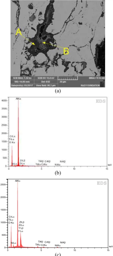
3. 1. Isothermal Test Figure 1(a) shows a region
within the BC area which is oxidized during the APS process. Figures 1(b) and 1(c) show the EDS analysis of regions A and B, respectively. As it can be seen during the process, TGO and mixed oxides of Cr and Y are formed.
Figure 2 shows an SEM image of BC/TC interface of the sample which is being exposed to the temperature of 1070 °C for 120 hours. A semi-quantitative analysis of different regions is provided in Table 2.
It can be seen that a uniform thick layer of TGO is formed in region A. A mixed oxide clusters of Chromium (Cr, Al)2O3, Spinel Ni(Cr, Al)2O4 and Nickel oxide NiO (CSN) are formed in regions of B, C and D region, respectively. In order to assess the cohesiveness of BC/TC, four samples with a time exposure of 0, 24, 120 and 192h were studied.
Figure 3 shows the SEM images of samples with a time exposure of 0, 24, 120 and 192h, respectively. As it can be seen there is no sign of separation or crack formation in the as-sprayed sample (0 hours of time exposure) and sample with 24 hours of time exposure (Figures 3(a) and 3(b), respectively).
(a)
(b)
(c)
Figure 1. (a) SEM image of formed oxide after coating process (b) and (c) chemical analysis of regions A and B
Figure 2. Comparison of the present numerical results with the experimental data for deposition fraction of micro particles in flow rate of 60 l/min.
O Kα AlKα
TiKα TiKβ TiLα
CrKα CrKβ CrLα
NiKα NiKβ NiLα
Y Lα Y Lβ ZrLα ZrLβ
keV 0
500 1000 1500 2000 2500
0 5 10 15
TABLE 1. A semi-quantitative analysis of different regions
Al
(W%) (W%)Ni (W%) Cr (W%) Zr (W%) Y (W%) O
A 43.27 1.07 0.41 3.01 1.09 51.15
B 16.59 2.48 30.87 2.69 0.79 46.58
C 11.00 24.30 23.48 3.60 0.51 37.11
D 0.51 61.80 1.48 4.58 0.77 30.87
A partial and universal separation can be seen in Figure 3(c) (sample with a time exposure of 72 hours) and Figure 3(d) (sample with a time exposure of 120 hours), respectively. It can be concluded from Figure 3 that BC coated by APS method provides a strong bonding between ceramic layer and substrate in a way that separations almost occurs within TC layer not at the substrate/BC interface or within the BC, during the isothermal loading just like the behaviour of the bond coat applied by other methods as reported in literature [11, 20, 21].
(a)
(b)
(c)
(d)
Figure 3. SEM images of samples after exposing at high temperature for (a) 0 hour (b) 24 hours (c) 120 hours (d) 192 hours
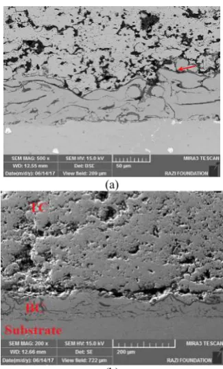
3. 2.Thermal Shock Test After thermal shock
test, all samples were observed using a scanning electron microscopy in order to identify any separation at the substrate/BC interface or within the bond coat.
Figure 4(a) shows the sample after 50 cycles of thermal shock test. This sample experienced no isothermal heat treatment. Figure 4(b) shows a sample with 120 hours of heat treatment at 1070 °C and 98 thermal shock test. As it can be seen no sign of separation or crack initiation is observable within the bond coat layer or at the substrate/BC interface and like an isothermal test, separation starts at BC/TC or within the TC layer.
(a)
(b)
4. CONCLUSION
Several experimental tests conducted in order to investigate the durability of bond coat layer applied using APS method under various thermal tests and oxidation behavior of bond coat during the coating process and after thermal loading. The results show that:
1. During the coating process, several layers of Al, Cr and Ni oxides form.
2. After thermal loading at 1070 °C for 120 hours several thick layers of TGO and CSN layers forms in the BC/TC interface.
3. Neither the oxides within the BC nor those at the BC/TC interface lead to no separation at substrate/BC or within the BC and the TBC system shows good durability under thermal shocks and isothermal loading.
Therefore, deposition of BC using APS method considering its durability and low economic costs can be a suitable method in applying bond coat layer of a TBC system.
5. REFERENCES
1. M. Belmonte, “Advanced ceramic materials for high temperature
applications,” Advanced Engineering Materials, Vol. 8, No. 8 (2006): 693-703.
2. Q. Tang, J. Dai, C. Bu, L. Qi, and D. Li, “Experimental study on debonding defects detection in thermal barrier coating structure
using infrared lock-in thermographic technique,” Applied
Thermal Engineering, Vol. 107, (2016): 463-468..
3. R. C. Read, “The Superalloys Fundamentals and Application,”
Cambridge, UK, 2006.
4. T. S. Hille, T. J. Nijdam, A. S. J. Suiker, S. Turteltaub, and W. G. Sloof, “Damage growth triggered by interface irregularities in thermal barrier coatings,” ActaMaterialia, Vol. 57, No. 9, 2(009), 2624–2630,.
5. A. Arizmendi-morquecho, G. Vargas, and J. M. Almanza,
“Ultra-low thermal conductivity thermal barrier coatings from recycled fly-ash cenospheres,” ActaMaterialia, Vol. 59, (2011), 2556– 2562.
6. C. R. C. Lima and R. da Exaltacaão Trevisan, “Temperature measurements and adhesion properties of plasma sprayed thermal barrier coatings,” Journal of Thermal Spray Technology, Vol. 8, No. 2, (1999), 323–327.
7. C. J. Li, Y. Li, G. J. Yang, and C. X. Li, “A novel plasma-sprayed durable thermal barrier coating with a well-bonded YSZ interlayer between porous YSZ and bond coat,” Journal of
Thermal Spray Technology, Vol. 21, No. 3–4, (2012), 383–390,.
8. N. J. Simms, P. J. Kilgallon, C. Roach, and J. E. Oakey, “Development of oxides at TBC–bond coat interfaces in burner
rig exposures,” Materials at High Temperatures, Vol. 20, No. 4 (2003): 519-526.
9. A. Peichl, T. Beck, and O. Vöhringer, “Behaviour of an EB-PVD
thermal barrier coating system under thermal–mechanical fatigue loading,” Surface Coatings Technology, Vol. 162, No. 2–3, (2003) 113–118.
10. Z. Lu, S.-W. Myoung, Y.-G. Jung, G. Balakrishnan, J. Lee, and U. Paik, “Thermal fatigue behavior of air-plasma sprayed thermal barrier coating with bond coat species in cyclic thermal exposure,” Materials (Basel), Vol. 6, No. 8, (2013) 3387–3403. 11. J. A. Haynes, M. K. Ferber, W. D. Porter, and E. D. Rigney,
“Mechanical properties and fracture behavior of interfacial alumina scales on plasma-sprayed thermal barrier coatings,”
Materials at High Temperatures, Vol. 16, No. 2, (1999), 49–69.
12. S. J. Bull, R. I. Davidson, E. H. Fisher, A. R. McCabe, and A. M. Jones, “A simulation test for the selection of coatings and surface treatments for plastics injection moulding machines,” Surface
Coatings Technology, Vol. 130, No. 2–3, (2000) 257–265.
13. D. Toma, W. Brandl, and U. Köster, “Studies on the transient stage of oxidation of VPS and HVOF sprayed MCrAlY coatings,”
Surface Coatings Technology, Vol. 120, (1999) 8–15, 1999.
14. Di Ferdinando, M., Fossati, A., Lavacchi, A., Bardi, U., Borgioli, F., Borri, C., Giolli, C. and Scrivani, A., "Isothermal oxidation resistance comparison between air plasma sprayed, vacuum plasma sprayed and high velocity oxygen fuel sprayed conicraly bond coats", Surface and Coatings Technology, Vol. 204, No. 15, (2010), 2499-2503.
15. K. Torkashvand, E. Poursaeidi, and M. Mohammadi, “Effect of TGO thickness on the thermal barrier coatings life under thermal shock and thermal cycle loading,” Ceramics International, Vol. 44, No. 8, (2018), 9283-9293.
16. L. Wang, Y. Wang, X. G. Sun, J. Q. He, Z. Y. Pan, and C. H. Wang, “Thermal shock behavior of 8YSZ and double-ceramic-layer La2Zr2O7/8YSZ thermal barrier coatings fabricated by atmospheric plasma spraying,” Ceramics International, Vol. 38, No. 5, pp. 3595–3606, 2012.
17. D. E. Crawmer, “Thermal spray processes,” Handbook of
ThermalSprayTechnology., 54–84, 2004.
18. C. Zhou, Q. Zhang, and Y. Li, “Technology Thermal shock behavior of nanostructured and microstructured thermal barrier coatings on a Fe-based alloy,” Surface Coatings Technology,
Vol. 217, 70–75, 2013.
19. Zhong, X., Zhao, H., Zhou, X., Liu, C., Wang, L., Shao, F., Yang, K., Tao, S. and Ding, C., "Thermal shock behavior of toughened gadolinium zirconate/ysz double-ceramic-layered thermal barrier coating", Journal of Alloys and Compounds, Vol. 593, No., (2014), 50-55.
20. A. Rabiei and A. G. Evans, “Failure mechanisms associated with the thermally grown oxide in plasma-sprayed thermal barrier coatings,” ActaMaterials, (2000), Vol. 48, No. 15, 3963–3976. 21. R. Vaßen, S. Giesen, and D. Stöver, “Lifetime of plasma-sprayed
thermal barrier coatings: comparison of numerical and experimental results,” Journal of Journal of Alloys and
Compoundsermal. SprayTechnology, Vol. 18, No. 5–6, (2000),
Air Plasma Sprayed Bond Coat Oxidation Behavior and its Resistance to Isothermal
and Thermal Shock Loading
E. Poursaeidi, K. Torkashvand, M. Mohammadi
Mechanical Engineering Department, Faculty of Engineering, University of Zanjan, Zanjan, Iran
P A P E R I N F O
Paper history:
Received 23 June 2018
Received in revised form 28 April 2019 Accepted 03 May 2019
Keywords:
Thermal barrier coating Air plasma sprayed Oxidation Failure
!
.#$ ) &
BC
( ( )
# * &
)
TC
( ( + , - .# *
! . /
0 1 2 ) !
TBC
3# 4$ 56 7 $ 8 9 # * : (
8 .8 ;+ < 8=> ? # ! ! 9 # * :
@ 1 3# A &
A B 9/ 2 0
TBC
56 8C .8 3# 4$ 3# 9 !
$ $ ! 56 #;
3- D E
$ +
-$ .#F : 6 G H
I * - - 9 $ JK
- 4 ! * # 9 - L D
! 1 3- D & * : )MI N
9 # ? O< &
9
3-! 6#$ P ? O<
& 9 -- &
3# $
-.
doi: 10.5829/ije.2019.32.06c.11