Please cite this article as: S. Abbasi, M. Zeinali, P. Nejadabbasi, Autonomous Underwater Vehicle Hull Geometry Optimization Using a Multi-objective Algorithm Approach, International Journal of Engineering (IJE), IJE TRANSACTIONS C: Aspects Vol. 31, No. 9, (September2018) 1593-1601
International Journal of Engineering
J o u r n a l H o m e p a g e : w w w . i j e . i rAutonomous Underwater Vehicle Hull Geometry Optimization Using a
Multi-objective Algorithm Approach
S. Abbasi*a, M. Zeinalib, P. Nejadabbasib
a School of Mechanical Engineering, Arak University of Technology, Arak, Iran
b School of Mechanical Engineering, Iran University of Science and Technology, Tehran, Iran
P A P E R I N F O
Paper history:
Keywords:
Autonomous Underwater Vehicles Hull Shape Design
Multi-objective Optimization
A B S T R A C T
In this paper, a new approach to optimize an Autonomous Underwater Vehicle (AUV) hull geometry is presented. Using this methode, the nose and tail of an underwater vehicle are designed, such that their length constraints due to the arrangement of different components in the AUV body are properly addressed. In the current study, an optimal design for the body profile of a torpedo-shaped AUV is conducted, and a multi-objective optimization scheme based on the optimization algorithm Non-dominated Sorting Genetic Algorithm-II (NSGA-II), as an evolutionary algorithm is employed. In addition, predefined geometrical constraints were considered so that equipment with the specific dimensions can be placed inside the AUV space without any effect on the AUV volume and the wetted surface. By optimizing the parameters of the newly presented profile, in addition to maximizing the volume and minimizing the wetted surface area, more diversed shapes can be achieved than with the ‘Myring’ profile. A CFD analysis of the final optimal design indicates that with the help of the proposed profile, the hydrodynamic parameters for the AUV hull were effectively improved.
doi: 10.5829/ije.2018.31.09c.16
NOMENCLATURE
L total length of the body (m) p static pressure (Pa)
n
L length of the nose (m) Greek Symbols
t
L length of the tail (m) density (kg/m3)
n
d diameter of nose blunt section (m) t turbulent viscosity
t
d diameter of tail base section (m) ij Cronker Delta
D body diameter (m) dynamic viscosity of the Newtonian fluid
tail angle Kinematic viscosity (m2/s)
f
CD friction drag coefficient k turbulent kinetic energy
p
CD pressure drag coefficient turbulent rate
U magnitude of free stream velocity (m/s)
1. INTRODUCTION*
With the population explosion in recent decades, there is a growing need for new sources of energy; and the oceans have vast energy possibilities and mineral resources. In
*Corresponding Author Email: [email protected](S. Abbasi)
recent years, autonomous underwater vehicles (AUVs) have gained a high status as important search and discovery tools for exploring the ocean depths. AUVs are free-swimming vehicles that rely on their own energy supply. The requirements of oceanography made Received 11 November 2017
researchers build the first AUVs in the 1970s and put them into commercial use in 1990s. Today AUVs are mostly used for scientific, commercial, and survey tasks [1].
The prestigious hydrodynamic hydrodynamics research centers and industries have a high regard for the design, manufacture and development of these autonomous underwater vehicles. The first and foremost concern preoccupying the minds of hydrodynamics researchers is having the best possible body design for an autonomous underwater vehicle. On this basis, the hydrodynamic behavior of streamlined bodies has been investigated by researchers to develop a family of axisymmetric bodies. The body shape of an underwater vehicle can influence its total body drag and the probability of cavitation occurrence in front of the nose, especially in high speed bodies. Estimating the shapes of the nose and the tail using polynomials constitutes the first step in presenting the body shapes of underwater vehicles via a specific group of profiles. In the laminar flow range, analyzing the flow around the bodies of underwater vehicles using analytical methods and then optimizing these types of bodies can be an effective step in full hydrodynamic assessment of different bodies [2]. The development of teardrop-shape bodies is one of the approaches taken for achieving optimized bodies in the laminar flow range. Although the use of streamlined bodies reduces the drag force, the unusual shapes and the fabrication difficulties of these types of bodies make their production costs very high. The use of elliptical, spherical, or conical profiles presents a preliminary idea for the design and fabrication of nose profiles. The Myring profile is currently the most famous profile used in the nose and tail designs of several underwater vehicles [3]. Functions with exponential forms can be used to estimate the nose and stern profiles of submerged vehicles [4]. To use these functions, their unknown coefficients must be determined in proportion to the desired body with the help of an algorithm.
The need to develop proper methods for finding the optimized body shape of an AUV has led to the development of algorithms that consider their architecting and manufacturing requirements as well as their hydrodynamic requirements. Minimizing the total drag force, maximizing the pressure distribution near the nose region, minimizing the flow noise, reduction of manufacturing costs and improved equipment efficiency are some of the conventional objective functions that are normally considered for the optimization algorithm of the body shape of an AUV.
Martz [5] applied a Multi Objective optimization using NSGA-II to optimize AUV geometrical characteristics and configuration of inner systems and achieve maximum effectiveness, minimum cost and minimum risk and then analyze some of the most optimum designs.
Joung [6] optimized the hull of an AUV with a ducted propeller and Myring suggested nose and tail profile with the help of CFD for a reduction in the resistance of the hull. Alvarez [7] used a simulated annealing algorithm to optimize an AUV hull with the goal of reaching minimum wave resistance and friction resistance in a unique volume of the AUV hull. Koh et al. [8] proposed a novel formulation for the optimal design of the endcap of AUVs and suggested conducting shape optimization and thickness optimization tasks simultaneously to determine hemiellipsoidal endcaps with a minimum weight. Vasudev et al. [9] used a non-dominated Sorting Genetic Algorithm NSGA−II and CFD analysis to optimize the design variables for minimization of an objective function (viscous resistance) and finally presented a design example motivated by its real world applications. Alam et al. [10] presented an optimization framework for the design of AUVs using a genetic algorithm (NSGA-II) and an infeasibility driven evolutionary algorithm (IDEA) to optimize the hull shape and arrange its contents to avoid interference and then analyzed optimization further with the help of the computer-aided design tool CATIA to generate a detailed design.
The present paper, by considering the restrictions pertaining to an AUV body design, presents general profile for designing the body profiles of these types of vehicles. With the help of this general profile, the architectural design limitations of the body can be easily incorporated and body profile coefficients can be determined, so that for a specific body length, a variety of profiles can be used in the hydrodynamic design. Between the various generated achievable profile designs, optimized coefficients are arised from a multi-objective optimization to achieve maximum inner volume and minimum wetted surface areas of the AUV hull. Finally, the results of optimization after a CFD analysis were compared with the Myring profile for geometric characteristics and the Hydrodynamic drag coefficient.
2. GEOMETRICAL DEFINITION OF THE AUV NOSE AND TAIL PROFILE
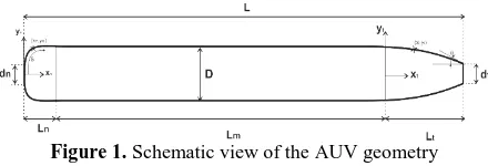
Figure 1. Schematic view of the AUV geometry
In order to study the effects of body shape on drag coefficient, Myring developed a set of equations for the nose and tail profiles of the axisymmetric bodies. They are known as Myring profiles. In the Myring profile, the nose profile is obtained from a quasi-elliptical equation as Equation (1).
(1) 1/ 2 1 1 2 n n n x L r d L
Thus, for a certain length of nose Ln and body diameter
D, different profiles can be obtained by changing the values of n. The tail profile is obtained from an equation of 3rd degree in the Myring profile as Equation (2).
(2) 2 2 3 3 2
1 3 tan
2 2 tan n m t t n m t t d
r D x L L
L L
d
x L L
L L
So, for a given tail length Lt and body diameter D, it is possible to generate different profiles for the tail by changing the tail angle θ. In case, where there is a blunt part of definite size at the nose head or tail end due to the design constraints, it is necessary to use an offset parameter in the nose or tail using the Myring profile. This can contradict other design constraints, such as the required volume in the nose or the tail parts. Therefore, in the current work, a general equation compatible with the geometric constraints of the body architectural design is proposed. Equation (3) is used to determine the nose profile. It would also be possible to generate different profiles based on those suggested equation.
(3) ( ) ( ) 2 n n n n n n n
n n n
n n n n X A L X dn Y X D d B
L X C L
The geometrical constraints are applied to the nose of the AUV in Equation (3) as following:
(4)
A definite profile can thus be obtained using different sets of unknown coefficients. The range of variations for the unknown coefficients of the problem can be limited, such that they put no effect on the variety of the developed profiles. By variation of the coefficients in the range under study, the final acceptable coefficients for development of the nose profile can be obtained. This means that the acceptable coefficients for the nose profile will be those having the profiles of positive slope and downward concavity of the curve:
(5)
By the same manner, the Equation 6 has been used to determine the tail profiles as follows:
( ) ( ) 2 t t t t t t t
t t t
t t t t X A L X D
Y X D d B
L X C L (6)
The geometrical constraints are applied to this equation as shown below; the number of unknown parameters will decrease:
(7)
The independent coefficients of the tail profile are estimated such that desired final profile will get a negative slope as well as a negative concavity:
(8)
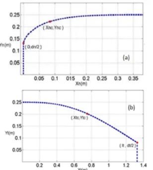
The challenge in designing an AUV hull is the possibility of installation of necessary parts within the hull. In addition, it is preferred to reduce the wetted surface area of an AUV body as much as possible without reducing its interior space. In the nose and tail sections of the investigated AUV, there are two interior parts that oblige the profiles to pass a specific point as illustrated in Figure 2. Therefore, it is indispensable to take advantage of an algorithm that helps for finding optimized profile:
( nc) Y nc
Y X , Xnc0.0847m , Ync0.222m (9)
( tc) Y tc
Y X ,Xtc0.7506m , Ytc0.20173m (10)
3. OPTIMIZATION FRAMEWORK
The optimization methods that could be employed can be divided into two major groups. The first group includes
( 0) 2
( ) 2
( 0)
( ) 0.0
n n n n n n n
Y X d
Y X L D
Y X
Y X L
0 ( ) 0
0 ( ) 0
n n n
n n n
X L Y X X L Y X
( 0) 2
( ) 2
( 0) 0
t t t t
t
Y X D
Y X L d
Y X
0 ( ) 0
0 ( ) 0
t t t
t t t
the gradient-based methods. That works on the basis of the objective function slope and can quickly converge to a solution. However, they suffer from two flaws: One is that they are sensitive to the primary points and the other drawback is the dependency of these methods on the slope of the objective function, which makes them impractical for problems with un-derivable objective functions. The second group of optimization approaches is evolutionary algorithms. These algorithms can be used for almost all types of problems. They are also used frequently in multi-objective optimization problems because once they are executed, they can come up with several optimum solutions, and they perform well for complex problems and problems with a large search space [11, 12]. Genetic algorithm is a very common evolutionary algorithm that relies on biological evolutionary traits, such as inheritance and mutation. In this research, a multi-objective optimization scheme based on the Non-dominated Sorting Genetic Algorithm (NSGA-II) employed in MATLAB software, because by using few computations, it can quickly arrive at the final solution, and also because of having an operator for calculating the crowding distance that provides an estimate of the density of solutions. It can provide a vast and uniform distribution of optimal designs. In solving multi-objective optimization problems, this algorithm yields a set of optimal solutions, none of which has a total superiority over the others; these solutions are called ‘non-dominated solutions’. In other words, a solution is called non-dominated or Pareto frontier if none of the objective functions can be improved in value without degrading some of the other objective values [13].
The objectives of the present work are to minimize the wetted surface area and maximize the interior spaces of the nose section and tail section of an AUV, while the geometrical constraints of the problem are satisfied. Concise mathematical definitions of this problem are presented in Tables 1 and 2. Optimization is performed separately for each of the nose and tail sections.
In present work, an initial population is first selected. This population is randomly chosen from a space that satisfies all the geometrical constraints, and then within a cycle, the next generations (offspring) are generated with the help of the ‘crossover’ and ‘mutation’ operators. The constraints of Tables 1 and 2, which are in the form of equalities, limit the acceptable ranges of some variables and, by being placed in the system of equations, obtain some variables in terms of other variables, which reduces the variable coefficients [14]. To manage the constraints related to the slope and concavity of the profile curve, Equation (5) and Equation (8) are in the form of inequalities, and since even the least violation of the constraints is not acceptable, then the death penalty method is applied. In this approach, the cost for offspring that do not satisfy the constraints is set, such that it would be impossible to select them as new parents for example,
their volume is set to a small value (zero), and their wetted surface area is set to a large value. In this way, the improbable values will be almost disregarded. For more information on the methods of constraints management, one can refer to literature [15].
After generating the offspring, an assessment of the populations of parents and offspring is conducted and members (equal in number to the initial population) are generated as the parents of the next generation, provided that there is no other member more optimal than them in terms of both volume and surface area criterion. In addition, they must have the farthest crowding distance, so they can cover a wider range of solutions.
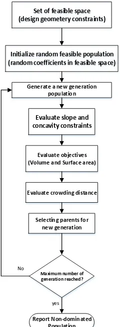
These new parents are non-dominated solutions, which means that each of these points has the largest possible volume for a specific surface area. The flowchart for the optimization procedure for this problem is shown in Figure 3. The parameters of the genetic algorithm are specified in the Table 3.
Figure 2. Geometrical constrains at nose (a) and tail (b) parts
TABLE 1. Summarized mathematical algorithm definition for nose
Coefficient including in the equation
n
, ,C , , ,
n n n n n
A B Variables
Minimize(nose wetted area), Maximize(nose volume) Objectives
( ) 0
n
Y X
( ) 0
n
Y X
( n n) 2
Y X L D
'( n n) 0
Y X L
( n 0) n 2
Y X d
'( n 0)
Y X Costraints
TABLE 2. Summarized mathematical algorithm definition for tail
Coefficient including in the equation , ,C , , ,
t t t t t t
A B
Variables
Minimize(tail wetted area), Maximize(tail volume) Objectives
( ) 0
t
Y X
( ) 0
t
Y X
( t t) t 2
Y X L d
'( t 0) 0.0
Y X
( t 0) 2
Y X D
'( t 0) 0
4. RESULTS AND DISCUSSION
4. 1. Hull Profile Optimization By applying the
problem constraints for the ‘Myring’ profile, only one profile can be sketched for the nose and tail sections, as shown in Figure 4.
The family of profiles obtained through a multi-objective optimization of the presented profile coefficients for nose and tail are shown in Figures 5 and 6. With this profile, in spite of the applied geometrical constraints, a large variety of profiles with various volume and surface area values can be produced.
Set of feasible space (design geometery constraints)
Initialize random feasible population (random coefficients in feasible space)
Generate a new generation population
Evaluate slope and concavity constraints
Evaluate objectives (Volume and Surface area)
Evaluate crowding distance
Selecting parents for new generation
Maximum number of generation reached?
Report Non-dominated Population
yes No
Figure 3. Flowchart of NSGA-II for the problem
TABLE 3. Genetic algorithm parameters
Parameter Value
Population size 60
No. generations 200
No. evaluations 12000
Crossover probability 0.9
Mutation probability 0.2
Mutation Rate 0.2
Figure 4. Myring profile for nose (a) and tail (b)
Figure 5. Various profiles for the AUV nose
Figure 6. Various profiles for the AUV tail
The ‘Myring’ and optimum profile are simultaneously sketched in Figures 9 and 10 for nose and tail, respectively.
The selected optimum design coefficients for the nose and the equation coefficients for the nose of ‘Myring’ are shown in Tables 4 and 5, respectively. Also, nose volumes and wetted surface areas obtained for the selected optimum design and for ‘Myring’ are compared in Table 6.
Figure 7. Pareto frontier for nose profiles
Figure 8. Pareto frontier for tail profiles
Figure 9. Comparing the optimum nose profiles for current work ‘Optimum Profile’ and ‘Myring Profile’
Figure 10. Comparing the optimum tail profiles for current work ‘Optimum Profile’ and ‘Myring Profile’
The selected optimum design coefficients for the tail of presented profile and the equation coefficients for the tail of ‘Myring’ are shown in Tables 7 and 8, respectively. Also, the tail volumes and surface areas obtained for the selected optimum design and for ‘Myring’ are compared in Table 9.
The selected optimum designs for nose and tail have a smaller surface area and a larger volume relative to those for the ‘Myring’ profile, and further, based on the optimization objectives. The optimum designs for both the nose and tail sections are superior to those of the ‘Myring’ profile.
TABLE 4. Optimum nose profile coefficients
Cn Bn An γn βn αn
9.87400 -14.45660 5.08260 1.34130 1.22430 0.87661
TABLE 5. Myring’ nose profile coefficients
Offset (m) n
0.00144 7.70020
TABLE 6. Comparing the optimum nose profile geometries of ‘Myring’ and current work
Nose wetted surface area (m2) Nose volume (m3) Profile type
0.666540 0.065096 Myring
0.663000 0.065384 current work
TABLE 7. Optimum tail profile coefficients
Ct Bt At γt βt αt
-1.08910 5.58910 -5 3 4.88940 4.99490
TABLE 8. Myring’ tail profile coefficients
Offset (m) θ (rad)
0.37995 0.33224
TABLE 9. Comparing the optimum tail profile geometries of ‘Myring’ and current work
Profile type Tail volume (m3) Tail wetted surface area (m2)
Myring 0.17235 1.67900
Current work 0.17291 1.67660
4. 2. Numerical Simulation To evaluate the hydrodynamic performance of the presented profile, it is numerically simulated using with Ansys-Fluent software. Its hydrodynamic behavior is compared with the Myring profile. In this regard, as a first step, the incompressible flow around the body of the AUV is numerically investigated. In this paper, the realizable k
model [16] is employed to model the flow turbulence. In the present work, the axisymmetric problem with the appropriate boundary conditions is solved using a finite computational domain. With L being thetotal length of the body as shown in Figure 11. The computational domain is extended 1L upstream of the leading edge of the axisymmetric body, 1L above the body surface, and5L downstream from the trailing edge.
The solution was evaluated on a structured mesh. For the current work, it was found that a grid size of 60,000 cells is sufficient for the simulations, with the first grid point being located at y30. So, along with the turbulence model, a wall function based on the law of the wall was used [17].
In the numerical solution, the SIMPLE algorithm was used to compute the pressure field. The numerical schemes for the turbulent quantities transported upwind were set to the first order, and the central schemes were set to second-order for both pressure and velocity. The simulation is conducted at a Reynolds number of 3.0×10⁷. Where the Reynolds number is given by:
Re U L
(11)
where, U is the magnitude of free stream velocity, L is the AUV length, and
v
is the fluid kinematic.The total drag coefficient on a body is usually considered to be the summation of friction drag coefficient and pressure drag coefficient:
f p
CDCD CD (12)
where f
CD is the friction drag coefficient and CDpis pressure drag coefficient.
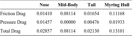
Simulations performed for the body profiles are presented in Tables 10 and 11 (i.e., presented and ‘Myring’ profiles) and the hydrodynamic effects due to the changes of body profile are analyzed. Table 10 shows the body drag coefficient for the AUV for the presented profile as well as the pressure and friction drag for the various body components. These findings for the ‘Myring’ body profile are presented in Table 11. As these two tables indicate, the changes in the nose and tail profiles of the AUV had a negligible effect on the amount of friction drag. While the pressure drag diminished a little in the presented profile relative to the “Myring’ profile, thereby slightly reducing the total body drag in the presented body profile (about 1 %).
TABLE 10. Pressure and friction drag for the various body components in the ‘Myring’ profile
Nose Mid-Body Tail Myring Hull
Friction Drag 0.01410 0.08114 0.01654 0.11168
Pressure Drag 0.01457 0.00000 0.00476 0.01933
Total Drag 0.02857 0.08114 0.02130 0.13101
TABLE 11. Pressure and friction drag for the various body components in the presented profile
Nose Mid-Body Tail Total Hull
Friction Drag 0.01400 0.08116 0.01654 0.11170
Pressure Drag 0.01370 0.00000 0.00470 0.01840
Total Drag 0.02760 0.08116 0.02134 0.13010
Figure 12. Distributions of pressure coefficient over the AUV body using the presented and “Myring’ profiles
The distributions of pressure coefficient over the AUV body using the two cases of presented and “Myring’ profiles are shown in Figure 12.
As Figure 12 indicates, there is not a great difference between the pressure distributions over the tail in these two cases. However, the patterns of pressure distribution over the nose indicate that the minimum pressure over the nose section is reduced in the presented profile 15 % relative to the ‘Myring’ profile, which then reduces the probability of cavitation occurrence on the nose in the presented profile. So in view of the obtained results, it can be reasoned that the use of the presented profile improves the hydrodynamic conditions of the AUV body.
5. CONCLUSION
wetted surface areas of the AUV body, by considering the geometrical constraints in the nose and tail sections of the AUV, and based on the proposed equation, several profiles were obtained the coefficients of which were determined via a constrained multi-objective optimization algorithm. Under the conditions with similar geometrical constraints for the body, the optimum profiles obtained in this work were compared to the profile resulting from the ‘Myring’ equation, and it was determined that the equation of the presented profile can yield various profiles, while only one profile can be achieved when using the ‘Myring’ equation.
This characteristic of the presented profile enables the designers to select a final hull shape so there is no interference between the AUV body shape and the internal parts that need to be installed. The results obtained from the simulation of flow around the body of the AUV indicate that by designing the hull shape with the help of the proposed profile, the minimum pressure over the nose section diminishes 15 % relative to the ‘Myring’ profile, which reduces the likelihood of cavitation on the nose when the presented profile is used. Moreover, in this case, the total body drag coefficient diminishes about 1 %.
6. REFERENCES
1. Sahu, B.K., and Subudhi, B., “The state of art of autonomous underwater vehicles in current and future decades”, in First International Conference Automation, Control, Energy and Systems (ACES), (2014).
2. Carmichael, B.H., “Underwater vehicle drag reduction through choice of shape”, AIAA Second Propulsion Joint Specialist Conference, (1996).
3. Packwood, A.R., and Huggins, A., “Afterbody shaping and transition prediction for a laminar flow underwater vehicle”, Ocean Engineering, (1994), 445–459.
4. Myring, D., “A theoretical study of body drag in subcritical axisymmetric flow”, Aeronaut. Technical Report, Royal Aircraft Establishment, Hants, UK, Q. 27, (1976), 186 -194. 5. Martz, M., “Preliminary Design of an Autonomous Underwater Vehicle Using a Multiple-Objective Genetic Optimizer”, (Doctoral dissertation, Virginia Polytechnic Institute and State University), (2008).
6. Joung, T.-H., Sammut, K., He, F., and Lee, S.-K., “Shape optimization of an autonomous underwater vehicle with a ducted propeller using computational fluid dynamics analysis”,
International Journal of Naval Architecture and Ocean Engineering, Vol. 4, No. 1, (2012), 44–56.
7. Alvarez, A., Bertram, V., and Gualdesi, L., “Hull hydrodynamic optimization of autonomous underwater vehicles operating at snorkeling depth”, Ocean Engineering, Vol. 36, No. 1, (2009), 105–112.
8. Koh, S.K., Jung, S.-Y., and Lee, N.J., “Optimal design of AUV endcaps”, OCEANS’11 MTS/IEEE KONA, IEEE (2011), 1–6. 9. Vasudev, K.L., Sharma, R., and Bhattacharyya, S.K., “A
CAGD+CFD integrated optimization model for design of AUVs”, Oceans Engineering, , (2014), 1–8.
10. Alam, K., Ray, T., and Anavatti, S.G., “Design and construction of an autonomous underwater vehicle”, Neurocomputing, Vol. 142, No. 142, (2014), 16–29.
11. Sadati, A., Tavakkoli-Moghaddam, R., Naderi, B., and Mohammadi, M., “Solving a New Multi-objective Unrelated Parallel Machines Scheduling Problem by Hybrid Teaching-learning Based Optimization”, International Journal of Engineering - Transactions B: Applications, Vol. 30, No. 2, (2017), 224–233.
12. Deb, K., Pratap, A., Agarwal, S., and Meyarivan, T., “A fast and elitist multiobjective genetic algorithm: NSGA-II”, IEEE Transactions on Evolutionary Computation, Vol. 6, No. 2, (2002), 182–197.
13. Chinneck, J.W., “Practical Optimization: a Gentle Introduction”, (2006). www.sce.carleton.ca/faculty/chinneck/po.html
14. Khalkhali, A., and Roshanfekr, S., “Multi-objective Optimization of a Projectile Tip for Normal Penetration”, International Journal of Engineering - Transactions A: Basics, Vol. 26, No. 10, (2013), 1225–1234.
15. Ponsich, A., Azzaro-Pantel, C., Domenech, S., and Pibouleau, L., “Constraint handling strategies in Genetic Algorithms application to optimal batch plant design”, Chemical Engineering and Processing: Process Intensification, Vol. 47, No. 3, (2008), 420– 434.
16. Shih, T., Liou, W., Shabbir, A., Yang, Z., Fluids, J.Z.-C.&, and 1995, undefined, “A new k-ϵ eddy viscosity model for high reynolds number turbulent flows”, Computers & Fluids, Vol. 24, No. 3, (1995), 227–238.
Autonomous Underwater Vehicle Hull Geometry Optimization Using a
Multi-objective Algorithm Approach
S. Abbasia, M. Zeinalib, P. Nejadabbasib
a School of Mechanical Engineering, Arak University of Technology, Arak, Iran
b School of Mechanical Engineering, Iran University of Science and Technology, Tehran, Iran
P A P E R I N F O
Paper history:
Received 11 November 2017
Received in revised form 21 January 2018 Accepted 23 February2018
Keywords:
Autonomous Underwater Vehicles Hull Shape Design
Multi-objective Optimization
هدیکچ
قم رد شور کی رضاح هلا هنیهب یارب دیدج
دب هسدنه یزاس را لرتنکدوخ یحطسریز هلیسو کی هن
نیا کمک هب .تسا هدش هئا
د شور هنوگ هب یحطسریز هلیسو مد و هغام یم یحارط یا
هندب لخاد رد توافتم ءازجا ییامناج زا یشان یلوط دویق هک دوش
و هندب یارب هنیهب یحارط کی رضاح شهوژپ رد .دریگ رارق هظحلام دروم ردژا یحطسریز هلیس
و تسا هدش ماجنا لکش ی
هنیهب شور چ یزاس هنیهب متیروگلا یانبم رب هفده دن یزاس
NSGA-II
یاهرتماراپ ندرک هنیهب اب تسا هدش هتفرگ راک هب
رب هولاع ،هدش هتفرگراک هب دیدج لیفورپ یسدنه ح ندرک ممیزکام
یم هندب مج .تفای تسد یرتمک هدش رت حطس هب ناوت
نآ نمض اقم رد هک یم گنبریام لوادتم لیفورپ اب هسی لکش زا یعونت هب ناوت
کی رد هندب یاه تسد صاخ یسدنه طیارش
هیبش .تفای ج یددع یزاس یم ناشن ییاهن هنیهب حرط رد نایر
یاهرتماراپ هدش هتفرگراک هب لیفورپ کمک هب هک دهد
هندب یکیمانیدوردیه هب لرتنکدوخ یحطسریز
یم دوبهب یرثوم روط .دبای