DOI: 10.22075/JRCE.2017.12541.1218
journal homepage: http://civiljournal.semnan.ac.ir/
Time-Dependent Structural Behavior of Repaired
Corroded RC Columns Located in a Marine Site
A. Farahani1* and M. Shekarchi2
1. Department of Civil Engineering, Tafresh University, Tafresh, Iran, P.O.Box 39518-79611 2. School of Civil Engineering, University of Tehran, Tehran, Iran, P.O.Box 11155-4563
Corresponding author: [email protected]
ARTICLE INFO ABSTRACT
Article history:
Received: 21 September 2017 Accepted: 31 October 2017
The chloride corrosion of reinforcing steel in reinforced concrete (RC) structures is a significant reason for premature deterioration and failure of RC structures in aggressive environments such as the Persian Gulf region. This is one of the most important sources of engineering and economic problems in developed countries. So, modeling chloride permeation and investigating different methods for the repair and maintenance of RC structures exposed to corrosive environments are very important for optimizing the service life and life cycle cost of these structures. In this research, a finite element model is applied to assess the time-dependent capacity of corroded RC structures using nonlinear analysis; this includes the impact of corrosion on inelastic buckling and low-cycle fatigue degradation of reinforcements. In this analysis, the influence of shotcrete repair after the initial cracking of concrete cover as a rehabilitation method on the performance of a corroded square RC column due to chloride-induced corrosion is investigated.
Keywords: Repair, Corrosion, Failure mode,
Reinforced Concrete Column, Shotcrete.
1. Introduction
The durability of reinforced concrete (RC) structures is significantly affected by the deterioration of their structural members. The deterioration caused by the corrosion of RC members is usually found to be one of the main sources of structural degradation which may eventually result in the serviceability failure of RC structures under service or extreme loading conditions. An accurate
1.1. Literature Review
A number of repair or rehabilitation methods have been developed for damaged RC structures, including concrete overlay, epoxy injection of cracks, shotcrete repair, external posttensioning, externally bonded steel or composite plates, externally bonded concrete, penetrant sealers, wrapped carbonfibers, and the addition of supplemental or replacement members, among others [1].
Chloride induced corrosion has two phases, initiation, and propagation, for RC structures in marine environments [2-4].
The initiation phase occurs when chloride penetrates into the concrete from its surface until the chloride concentration on the reinforced surface reaches a critical value of chloride concentration (Ccr), and until sufficient oxygen and moisture are present for corrosion time (Tcorr) to begin. The Ccr depends on several factors, including exposure conditions and the chloride ion value of the sea water [3].
The south of Iran has an aggressive marine environment with a high evaporation rate, high temperature, and a high concentration of salt in water, which enhances chloride-induced reinforcement corrosion [5,6]. Significant studies [4-7] have been performed on chloride-induced corrosion as a deterioration mechanism in RC structures such as bridge columns and jetty structures in such aggressive environments. Predicting chloride ingress into the concrete at the initiation phase based on Fick’s second law of diffusion is the main approach for durability design and service life determination of RC structures [8].
In the propagation phase, following the corrosion initiation time, the chloride
concentration increases on the reinforcement surface, the production of the corrosion reaction and iron rust begins, and the percentage of corrosion increases from zero after Tcorr.
Some researchers have developed empirical models for predicting the chloride diffusion coefficient [7,9-11] and surface chloride concentration [12-14] in concrete in the initiation phase of corrosion, and empirical models for predicting the corrosion rate using concrete resistance [15-18] in the propagation phase of corrosion.
As a result, in existing RC structures, repair and maintenance to decrease the chloride diffusion into the concrete and reduce the corrosion rate of the reinforcement seems to be significant.
Using shotcrete on the surface of the concrete after the initiation of crack time due to rust expansion will be effective at delaying the failure time of RC structures and increasing their service life.
beam was presumed to be the same as that for the non-damaged beam. The shotcrete repair showed very little effect on degradation in probabilistic analysis.
1.2. Research Significance
In this research, a performance-based model of the life cycles of corrosion-affected RC structures is proposed with a focus on the effect of propagation of reinforcement corrosion on structural deterioration. Timely maintenance and repairs have the potential to increasethe service life of corrosion-affected RC structures. The present study investigates the influence of using 15 mm shotcrete as a repair scenario in RC column with mixture design of PC concrete.
2. Analytical Studies
In this study, the nonlinear finite element modeling technique is employed by using the fiberbeam-column element developed Afsar Dizaj et al. [21] to simulate the flexural response columns. The modeling technique has been calibrated and validated for a rectangular RC column of bridge piers, for both uncorroded and corroded columns [21].
A nonlinear fiber beam-column element is a line element in which the moment-curvature response at selected locations is determined from the fibersection assigned to that integration point. In RC columns, the most inelastic behavior occurs near the base of the column [22]. To model the strain penetration and the slippage of reinforcement anchored to the foundation, a zero-length section element is used. Examples are modeled in OpenSees 2012 finite element software. A detailed discussion of the elements and zero-length section are available in reference [21].
By using the verified a finite element model of a square cross-section column, the time-dependent structural capacity of this column is investigated.
The section dimension, height of column, initial concrete cover, diameter of longitudinal reinforcement, number of longitudinal reinforcements in each section, diameter of horizontal reinforcements (ties) and tie spacing of circular column are equal to 250 mm, 1800 mm, 35 mm, 16 mm, 8, 8 mm and 80 mm, respectively.
The mechanical properties of vertical and horizontal tie reinforcement are presented by Afsar Dizaj et al. [21]. The concrete compressive strength is considered to be 30 MPa. To investigate the effect of corrosion on time-dependent displacement ductility and strength loss of corroded RC columns, different degrees of corrosion (i.e., mass loss ratios) are considered. Analyses are conducted for constant axial force ratio 0.1 (Nu /σcAc), where Nu is the axial force, σc is the compressive strength of concrete and Ac is the gross cross-section area of column cross-section. It is worth mentioning that corrosion of horizontal ties is also considered in these analyses.
corroded RC square column in the finite element model is investigated by static nonlinear pushover analysis. Moreover, structural performance and failure modes of the repaired corroded square column are analyzed and the performance of the repair scenario is investigated.
3. Results and Discussion
3.1. Chloride Diffusion Coefficient Model In this research, the diffusion coefficient model for PC concrete in the tidal zone of Qeshm Island in the south of Iran is used based on experimental data developed by Farahani [23]. 1 4 4 2571 . 0 / 0157 . 1 (-12) ) 100 ( ) 100 ( 1 ) 1 1 ( exp 43.482) / 56.8 1 ( 10 c ref c w ref h h T T R U t t c w D (1) where, t is the current time (in months), tref represents reference time (tref = 3 months) and n is the age factor, taking into account the time dependence of the chloride penetration into the concrete. w/c is the water-to-cement ratio (0.35w/c0.50). For the temperature function, U (in J.mol-1) presents the activation energy of diffusion process, R is the gas constant (8.314 J. mol-1.K-1), T is the current temperature (in K), and Tref denotes reference temperature (Tref = 306.5 K). The value of U/R ratio for the Persian Gulf region has been predicted as 2948 K [24]. For the relative humidity function, h ( in percent) presents the relative humidity of concrete specimen, and hc is the critical humidity level at which the diffusion coefficient drops halfway between its maximum and minimum values (≈75%).
3.2. Surface Chloride Concentration Model
The surface chloride concentration model for PC concrete in the tidal zone in the south of
Iran is used based on experimental data developed by Khaghanpour et al. [12].
0 d
C
K
t
Cs (2)
where, Cs (in % weight of concrete) is the surface chloride concentration, K, d, and C0 are variable with water-to-cement ratio.
3.3. Corrosion Initiation Time
The corrosion initiation time (Tcorr in s) of longitudinal or horizontal reinforcement is calculated by Eq. (3). Eq. (3) is calculated by using the analytical solution of Fick‘s second law of diffusion for 1D presented by Luping [25]. 2 2 4 i s cr s corr C C C C erfinv D x T (3) where, Ci (in % weight of concrete) is the initial chloride concentration experimentally equals to 0.015% weight of concrete for PC concrete [23,24] in Qeshm Island. D (in m2/s) is the proposed chloride diffusion coefficient model in Eq. (1). x (in m) is the required cover thickness for PC concrete in time t (in s) that the distance between the surface of concrete and surface of longitudinal bars, and between the surface of concrete and surface of horizontal bars are shown by bar_depth and tie_depth, respectively.
wharves and jetty structures in the marine environments are degrading at an early age in the service life of structures due to chloride-induced corrosion. Therefore, preventing this destruction and increasing the service life of these structures is necessary for corrosive marine environments.
3.4. The diameter of longitudinal and horizontal bars after corrosion initiation
The reduced diameter of longitudinal (dt)
and horizontal (dt_tie) bars, are calculated by Eqs. (4) and (5), respectively.
avg P d
dt 0
(4)tie avg
tie P
d tie
dt_ 0_ _ (5)
The value of α is 2 for uniform corrosion and varied from 4 to 8 for pitting corrosion [26].
0
d and d0_tie are the initial diameters of
longitudinal and horizontal bars, respectively. The Pave(t) is average corrosion penetration depth based on the uniform volumetric mass loss at time t after corrosion initiation which can be calculated as follows:
( ) ( )
corr
t
ave T corr
P t
i t dt(6) where, κ is the conversion factor from
μA/cm2 to mm/year that equals to 0.0116,
and icorr(t) is presented the corrosion current
density of reinforcements at the time after the corrosion initiation time (Tcorr) calculated by Eqs. (7) and (8) [18]:
x c w icorr 64 . 1 0 ) / 1 ( 8 .
37
(7)
29 . 0
0( )
85 . 0 )
( corr corr
corr t i t T
i (8)
3.5. Crack initiation time
Liu and Weyers [27] suggested an empirical model for prediction of the crack initiation time
(tcr) is calculated by Eq. (9).
p crit cr k W t 2 2 (9) ( ) 10 8 .
9 5 d0i t
k corr p (10) where, Wcrit is the total amount of critical rust products needed to fill the volumes of pores and rust expansion, kp is the rate of the production of corrosion products given by the empirical Eq. (10) suggested by Val [28]. where, is the ratio between the molecular weight of steel and molecular weight of
corrosion products, and d0 is the initial
diameter of the bar. Further details and derivation are available in [28].
The crack initiation time of the concrete cover of the no-repair scenario for PC concrete with 0.35, 0.40 and 0.50 water-to-cement ratios are calculated by Eq. (9) equal to 3.90, 3.53 and 2.69 years, respectively.
3.6. Corrosion Percentage
Finally, Eqs. (11) and (12) present the corrosion percent of longitudinal () and horizontal
( _tie) bars, respectively.
2 0 1 100 d dt (11) 2 _ 0 _ 1 100 _ tie d tie dt tie
(12)repair scenario at the crack initiation time of PC concrete with different water-to-cement ratios 0.35, 0.40 and 0.50.
Fig. 1 (b) shows the corrosion percentage of longitudinal and horizontal bars decrease 32% and 37%, respectively by using the shotcrete as a repair than no repair scenario, Fig. 1 (a).
Fig. 2 (b) shows the corrosion percentage of longitudinal and horizontal bars decrease 32% and 36.9%, respectively, by using the shotcrete as a repair than no repair scenario, Fig. 2 (a).
Fig. 3 (b) shows the corrosion percent of longitudinal and horizontal bars decrease 35.9% and 41.4%, respectively by using the shotcrete as a repair than no repair scenario, Fig. 3 (a).
To investigate the influence of repair scenario on the structural performance of corroded columns, a series of time-dependent nonlinear pushover analyses have been conducted with various corrosion percentages.
(a)
(b)
Fig. 1. Corrosion percentage of longitudinal and horizontal bars over time; (a) No Repair, (b)
using shotcrete. (w/c=0.35).
(a)
(b)
Fig. 2. Corrosion percentage of longitudinal and horizontal bars over time; (a) No Repair, (b)
using shotcrete. (w/c=0.40).
0 2 4 6 8 10 12 14 16 18 20 22
0 2 4 6 8 10
Co
rr
o
sio
n
P
er
ce
n
t (
%)
Time after Tcorr (year) LR
HR
0 2 4 6 8 10 12 14
0 2 4 6 8 10
Co
rr
o
sio
n
P
er
ce
n
t (
%)
Time after Tcorr (year) LR
HR
0 2 4 6 8 10 12 14 16 18 20 22
0 2 4 6 8 10
C
o
rr
o
sio
n
P
er
ce
n
t (
%)
Time after Tcorr (year) LR
HR
0 2 4 6 8 10 12 14
0 2 4 6 8 10
C
o
rr
o
sio
n
P
er
ce
n
t (
%)
Time after Tcorr (year) LR
(a)
(b)
Fig. 3. Corrosion percentage of longitudinal and horizontal bars over time; (a) No Repair, (b)
using shotcrete. (w/c=0.50).
3.7. Nonlinear behavior, failure modes, and time-dependent capacity
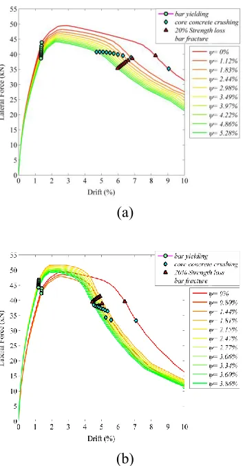
Figs. 4-6 show the results of monotonic pushover analyses. According to Figs. 4-6 (a), for the axial force ratio (ratio of axial force to section area and compressive strength) of 0.1, the failure mechanism of the square column, apart from the corrosion percentage equals to 0% mass loss; before 20% strength loss, it is core concrete crushing in compression. So, the distance between core concrete crushing in compression failure mode and 20% strength loss increases by increasing the water-to-cement ratio and the corrosion percentage.
However, for any corrosion levels, bar fracture in tension failure mode not happen. As it is shown in Figs. 4-6 (b), by using the 15 mm shotcrete on the surface of concrete and using the same concrete mix design at the crack initiation time, results in a reduction in the corrosion percentage of a corroded square column compared to the previous no-repair scenario. Moreover, approximately up to 3.85%, 4.12% and 4.53% mass loss for 0.35, 0.40, and 0.50 water-to-cement ratio, respectively, the core concrete crushing failure mode occurs after 20% strength loss; just bar yielding is the dominant failure mode. Thus, the structural performance of the corroded square column increases by repairing with shotcrete. However, beyond 3.85%, 4.12% and 4.53% mass loss for 0.35, 0.40 and 0.50 water-to-cement ratio, respectively, core concrete crushing failure mode overtakes from 20% strength loss. Moreover, comparison between the shotcrete repair scenario and the no-repair scenario indicates that using 15 mm shotcrete on the concrete surface causes the core concrete crushing in compression failure mode and 20% strength loss close to each other. So, using the 15 mm shotcrete causes the corrosion levels are less than no-repair. Moreover, using 15 mm shotcrete increases structural capacity and performance of corroded RC square column.
(a)
0 2 4 6 8 10 12 14 16 18 20 22
0 2 4 6 8 10
Co
rr
o
sio
n
P
er
ce
n
t (
%)
Time after Tcorr (year) LR
HR
0 2 4 6 8 10 12 14
0 2 4 6 8 10
C
o
rr
o
sio
n
P
er
ce
n
t (
%)
Time after Tcorr (year) LR
(b)
Fig. 4. Pushover curve; (a) No Repair, (b) using shotcrete. (w/c=0.35).
(a)
(b)
Fig. 5. Pushover curve; (a) No Repair, (b) using shotcrete. (w/c=0.40).
(a)
(b)
Fig. 6. Pushover curve; (a) No Repair, (b) using shotcrete. (w/c=0.50).
4. Conclusion
Inspection, repair, and maintenance of corroded RC structures exposed to marine environments such as the south of Iran are essential for improving the structural performance, durability and service life of these structures.
square RC column due to chloride-induced corrosion are investigated.
Results indicate that using 15 mm shotcrete causes the core concrete crushing occurs after 20% strength loss at each corrosion level. It is noteworthy that increasing the water-to-cement ratio causes the core concrete crushing in compression failure mode to occur near to 20% strength loss in high corrosion levels.
REFERENCES
[1] LeRoy, D.H., and Kauhl, N.E. (1997). "Rehabilitation of the Macomb dam bridge." Practical Solutions for Bridge Strengthening and Rehabilitation, Washington.
[2] Vaysburd, A.M., and Emmons, P.H. (2004). "Corrosion inhibitors and other protective systems in concrete repair: concepts or misconcepts." Cement and Concrete Composites (Elsevier), Vol. 26, pp. 255-263.
[3] Alizadeh, R., Ghods, P., Chini, M., Hoseini, M., Ghalibafian, M., Shekarchi, M. (2008). "Effect of curing conditions on the service life design of RC structure in the Persian Gulf region." Journal of Materials in Civil Engineering (ASCE), Vol. 20(1), pp. 2-8. [4] Ghoddousi, P., Ganjian, E., Parhizkar, T.,
Ramezanianpour, A.A. (1998). "Concrete technology in the environmental conditions of Persian Gulf." BHRC Publication. [5] Temperley, T.G. (1965). "Corrosion
phenomena in the Coastal areas of the Persian Gulf." Corrosion Science (Elsevier), Vol. 5, pp. 581-589.
[6] Valipour, M., Pargar, F., Shekarchi, M., Khani, S., Moradian, M. (2013). "In situ study of chloride ingress in concretes containing natural zeolite, metakaolin and silica fume exposed to various exposure conditions in a harsh marine environment." Construction and Building Materials (Elsevier), Vol. 46, pp. 63-70.
[7] Farahani, A., Taghaddos, H., Shekarchi, M. (2018). "Chloride diffusion modeling in pozzolanic concrete in marine site." ACI Materials Journal, Vol. 115, pp. 509-518. [8] Rodrigues, M.P.M.C., Costa, M.R.N.,
Mendes, A.M., Eusebio Marques, M.I. (2000). "Effectiveness of surface coatings to protect reinforced concrete in marine environments." Materials and Structures (Springer), Vol. 33, pp. 618-626.
[9] Ehlen, M.A. (2012). "Life-365™ Service Life Prediction Model™ and computer program for predicting the service life and life-cycle cost of reinforced concrete exposed to chlorides." Manual of Life-365™ Version 2.1, Produced by the Life-365™ Consortium II.
[10] Ferreira, R.M. (2010). "Optimization of RC structure performance in marine environment." Engineering Structures, Vol. 32, pp. 1489-1494.
[11] Saetta, A.V., Scotta, R.V., Vitaliani, R.V. (1993). "Analysis of chloride diffusion into partially saturated concrete." ACI Materials Journal (ACI), Vol. 90, pp. 441-451.
[12] Khaghanpour, R., Dousti, A., Shekarchi, M. (2016). "Prediction of cover thickness based on long-term chloride penetration in a marine environment." Journal of Performance of Constructed Facilities (ASCE), Vol. , pp. 1-10.
[13] Ann, K.Y., Ahn, J.H., Ryou, J.S. (2009). "The importance of chloride content at the concrete surface in assessing the time to corrosion of steel in concrete structures." Construction and Building Materials (Elsevier), Vol. 23, pp. 239-245.
[14] Costa, A., Appleton, J. (1999b). "Chloride penetration into concrete in marine environment; Part II: Prediction of long term chloride penetration." Materials and Structures, Vol. 32, pp. 354-359.
[16] Alonso, C., Andrade, C., Gonzalez, J. (1988). "Relation between resistivity and corrosion rate of reinforcements in carbonated mortar made with several cement types." Cement and Concrete Research (Elsevier), Vol. 8, pp. 687-698. [17] Kong, Q., Gong, G., Yang, J., Song, X.
(2006). "The corrosion rate of reinforcement in chloride contaminated concrete." Low Temperature Architecture Technology, Vol. 111, pp. 1-2.
[18] Vu, K.A.T., Stewart, M.G. (2000). "Structural reliability of concrete bridges including improved chloride-induced corrosion models." Structural Safety (Elsevier), Vol. 22, pp. 313-333.
[19] Choe D., Gardoni P., Rosowsky D., Haukaas T. (2008). "Probabilistic capacity models and seismic fragility estimates for RC columns subject to corrosion." Reliab Eng Syst Safe, Vol. 93, pp. 383-393.
[20] Enright, M.P., Frangopol, D.M. (1999). "Maintenance planning for deteriorating concrete bridges." Journal of Structural Engineering (ASCE), Vol. 125(12), pp. 1407-1414.
[21] Afsar Dizaj, E., Madandoust, R., Kashani, M.M. (2018). "Exploring the impact of chloride-induced corrosion on seismic damage limit states and residual capacity of RC structures." Structure and Infrastructure Engineering (Taylor and Francis), Vol. 14, pp. 714-729.
[22] Berry, M.P., and Eberhard, M.O. (2006). "Performance modeling strategies for modern reinforced concrete bridge columns." Pacific Earthquake Engineering Research Center, University of California, Berkeley.
[23] Farahani, A. (2014). "Performance evaluation of numerical models for study of chloride ion diffusion in concrete structures in Persian Gulf." M.Sc. Thesis, University of Tehran, School of Civil Engineering, Tehran, Iran, 154 pp.
[24] Farahani, A., Taghaddos, H., Shekarchi, M. (2015). "Prediction of long-term chloride diffusion in silica fume concrete in a marine environment." Cement and
Concrete Composites (Elsevier), Vol. 59, pp. 10-17.
[25] Luping, T. (1996). "Chloride Transport in Concrete, Measurement and Prediction." Ph.D. Dissertation, Chalmers University of Technology, Department of Building Materials, Goteborg, Sweden, 104 pp. [26] Vidal, T., Castel, A., Francois, R. (2004).
"Analyzing crack width to predict corrosion in reinforced concrete." Cement and Concrete Research (Elsevier), Vol. 34, pp. 165-174.
[27] Liu, Y., and Weyers, R.E. (1998a). "Modeling the time-to-corrosion cracking in chloride contaminated reinforced concrete structures." ACI Materials Journal (ACI), Vol. 95, pp. 675-681.
[28] Val, D.V. (2007). "Factors affecting life-cycle cost analysis of RC structures in
chloride contaminated