Failure Study of Hybrid Bonded-bolted Composite Single
and Double Lap Joints
E. Selahi
∗Mechanical Engineering Department, Marvdasht Branch, Islamic Azad University, Marvdasht, Iran.
Article info
Article history:
Received 13 October 2018 Received in revised form 03 February 2019
Accepted 10 February 2019
Keywords:
Failure Composite Hybrid joint Adherend Adhesive Bolt
Abstract
In this paper by employing ANSYS Workbench software and three-dimensional finite element simulation, failure analysis of hybrid bonded and bolted single and double lap joints with laminated composite adherends subjected to axial, shear and bending loads were performed. In order to select an appropriate and optimized element number, the convergence behavior of single and double lap joints were investigated. Then the failure study of each single and double lap hybrid composite joints for the three time dependent loading cases were performed. To demonstrate the validity and precision of the presented simulations, the obtained results were compared with the results presented in the available literatures. The results of this research indicated that, in the single lap joint subjected to axial load, the replacement of hybrid bonded bolted joint instead of adhesive joint leads to significant increase of 56%in the load bearing capacity of the joint.
Nomenclature
Db Bolt diameter Ei Modulus of elasticity
F Pre-tension load Fa Axial load
Fb Bending load Fsh Shear load
Gij Shear modulus P Pressure
Ssh Shear strength Suc Compressive strength
Sut Tensile strength Sy Yield stress
t Thickness ρ Density
µ Coefficient of friction ν Poisson’s ratio
1. Introduction
Tendency of replacing laminated fibrous composites, instead of metallic sheets in aeronautical, automobile and marine structures are increasing rapidly. Weight reduction is the main reason of this replacement, but fi-brous polymeric composites have many other privileges such as: corrosion resistance, wear resistance, thermal and acoustic insulation and simplicity of repairing pro-cesses.
Due to the size limitations for the construction and transportation of large composite structures, these structures are initially made in smaller parts and then joined together at the installation site. Adhesive joint is the most common connection method in compos-ite structures. Adhesive joints have a high resistance to shear, but have a relatively low resistance to peel-ing. Therefore, the idea was created that by adding a bolted joints at the place of adhesive joint, the peeling ∗Corresponding author: E. Selahi (Assistant Professor)
E-mail address: [email protected]
http://dx.doi.org/10.22084/jrstan.2019.17471.1072 ISSN: 2588-2597
strength can also be improved [1].
In recent years, considerable researches have been conducted to study the behavior of adhesive joints. The first attempt for analyzing of adhesive joints was carried out by Volkersen [2] in 1938. He modelled the adhesive layer of single lap joint, by continuous shear springs. In this model, the effects of bending moment (due to eccentricity of loading axes) was ignored. Hart-Smith [3-5] presented relations to investigate the single lap, double lap, stepped and scarf adhesive joints with isotropic adherends. In all abovementioned researches, adhesive layers were modeled as linear elastic materi-als.
The first attempt for finite element analysis of bonded joints was carried out by Adams et al. [6] in 1978. Finite element method was used for ana-lyzing the stress of single lap, double lap and dou-ble scarf adhesive joints. Harris and Adams [7] em-ployed nonlinear finite element modeling to investigate the strength of single lap adhesive joint. Bogdanovich and Kizhakkethara [8] applied three-dimensional finite element method to simulate the behavior of double lap composite joints.
Bahei-El-Din and Dvorak [9] simulated single lap composite adhesive joints with thick adherends, using a finite element method. Mortensen and Thomsen [10] analyzed the single lap adhesive joint with orthotropic laminates numerically. Recently, Selahi et al. [11-13] performed linear and nonlinear mathematical modeling to investigate the behavior of lap and tubular adhesive joints with composite adherends. In the field of hybrid bonded-bolted joints, few researches have been done. In the following paragraphs, most important of these researches are introduced.
Chan and Vedhagiri [14] used finite element method to simulate stress distributions in laminated composite bolted, bonded and hybrid joints. Kelly [15] simulated three-dimensional finite element model to investigate the load transfer in single lap hybrid bonded-bolted carbon fibre composite joints. Ding and Dhanasekar [16], investigated the behavior of bonded-bolted steel butt joints. Matsuzaki et al. [17] employed empir-ical tests on single lap bonding specimens of glass fiber to aluminum and investigated the changes in the shear strength of hybrid joints with respect to adhesive joints. Barut and Madenci [18] presented a mathemat-ical modelling to investigate peel and shear stress dis-tributions in the adhesive layer as well as bolts stress distributions in single-lap hybrid joints subjected to in-plane and lateral loads.
Hoang-Ngoc and Paroissien [19] used two- and three-dimensional finite element simulations to deter-mine the stress concentration factors in the lap bonded and hybrid (bolted-bonded) joints. Duc Hai and Mut-suyoshi [20] studied the force-displacement and stress distributions of double lap bolted-bonded joints of steel
plates in hybrid CFRP/GFRP laminates.
Venkateswarlu and Rajasekhar [21] used Ansys fi-nite element software to analyze stresses in hybrid composite joints. Bodjona et al. [22] employed fi-nite element simulations and also experimental testing to investigate the load sharing behavior of lap hybrid bonded-bolted joints. In all previous studies in the field of hybrid joint analysis, adherends were exposed to constant load. Moreover, in the most of the above-mentioned studies, only single lap joint was simulated. Therefore in this research by performing quasi-static analysis and gradual increase of applied force in single lap and double lap composite joints exposed to axial, shear and flexural loads, the failure load magnitude and the failure type in each of the above states were investigated.
2. Material and Methods
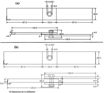
Geometry configuration of the hybrid bonded-bolted single and double lap joint specimens are illustrated in Fig. 1.
In both joints, the main adherends were combi-nation of three below layers: uni-directional e-glass epoxy, uni-directional carbon epoxy and woven roving carbon epoxy. The adherends in the single lap joint had the stacking sequences as follows:
[Carbon Uni/Carbon Woven/Glass Uni]sym In the double lap joint, the upper and lower ad-herends had the same stacking sequences with those in the single lap joint adherends. The thickness of mid adherend was twice of upper and lower adherends with the stacking sequences as follows:
[Carbon Uni/Carbon Woven/Glass Uni/Glass Uni/ Carbon Woven/ Carbon Uni]sym The adhesive layer was epoxy and bolt and nut were metallic. Table 1 lists the mechanical properties of each composite layer, adhesive layers between adherends and bolts and nuts.
Subscripts 1, 2 and 3 denotes longitudinal, trans-verse and thickness directions.
3. Theory and Calculations
In this section by employing ANSYS Workbench soft-ware, the three-dimensional finite element models of hybrid single lap and double lap composite joints were carried out. Then by performing the implicit solving methods and gradual increase of applied force, the fail-ure load magnitude and the failfail-ure type of these joints exposed to axial, shear and flexural loads, were deter-mined.
Fig. 1. Dimensions of hybrid a) Single lap and b) Double lap joints.
Table 1
Mechanical properties of composite layers, Adhesive and bolt and nut [23].
Material Mechanical properties
Uni-directional carbon-epoxy
E11= 123.3GPa,E22=E33= 7.78GPa, G12=G13= 5.0GPa,
G23= 3.08GPa,ν12=ν13= 0.27, ν23= 0.42,Sut−1= 1632MPa,
Sut−2 =Sut−3 = 34MPa,Suc−1 =−704MPa, Suc−2 =Suc−3=−68MPa,
Ssh−12=Ssh−13= 80MPa,Ssh−23= 55MPa,ρ= 1518kg/m3,t= 0.5mm
Woven roving carbon-epoxy
E11=E22= 59.16GPa,E33= 7.5GP a,G12= 17.5GPa,
G13=G23= 2.7GPa,ν12= 0.04,ν13=ν23= 0.3,
Sut−1=Sut−2= 513MPa,Sut−3= 50MPa,Suc−1=Suc−2=−437MPa,
Suc−3=−150MPa,Ssh−12= 120MPa,Ssh−13=Ssh−23= 55MPa,
ρ= 1451kg/m3, t= 1.0mm
Uni-directional eglass-epoxy
E11= 45Gpa,E22=E33= 10GPa,G12=G13= 5.0GPa,G23 = 3.85GPa,
ν12 =ν13 = 0.3, ν23 = 0.4, Sut−1 = 1100MPa, Sut−2 =Sut−3 = 35MPa,
Suc−1=−675MPa,Suc−2=Suc−3=−120MPa,
Ssh−12=Ssh−13= 80MPa,Ssh−23= 46MPa,ρ= 2000kg/m3,t= 0.5mm Epoxy adhesive E= 3780MPa,G= 1400MPa,ν = 0.35,Sut= 54.6MPa,
ρ= 1160kg/m3, t= 0.5mm
Bolts and nuts E= 200GPa,G= 77GPa,ν= 0.3,Sut= 460MPa,Sy= 250MPa,
ρ= 7850kg/m3, D
b= 8mm In this modeling, bonded contact conditions was se-lected for interfaces between the surfaces of composite laminated layers with each other and with the adhesive layer. Furthermore, frictional contact condition was considered for interfaces between bolts and holes walls and between composite layers and nut or head bolt.
ap-plied at the right side of the joints. All simulations included three steps as follows [24]:
(1) Applying pre-tension and torque loads according Eq. (1).
(2) Fixed preloads displacement.
(3) Applying axial, shear or bending loads and in-creasing, its magnitudes gradually until occur-rence of the failure.
T =µF Db (1) HereF = 1000N andµ= 0.2[20]. The time dependent of 3rd stage load relations are defined by Eqs. (2)-(4) for the single lap joint.
Fa= 125t (N) (2)
Fsh= 25t (N) (3)
Fb= 12.5t (N) (4) These time dependent load relations for double lap joint are defined by Eqs. (5)-(7).
Fa= 250t (N) (5)
Fsh= 50t (N) (6)
Fb= 25t(N) (7) The force vs. displacement (free side displacement) di-agrams of single lap and double lap hybrid joints sub-jected to axial, shear and bending loads are dawn in Fig. 2.
Failure of hybrid bolted-bonded joints are classified in three categories as follows:
(1) Adherend failure or delamination. (2) Adhesive peel or shear failure. (3) Bolt failure.
Based on Hashin failure criterion, adherend failure modes are related by Eqs. (8)-(12).
(1) Tensile fiber failure (σ1≥0) (
σ1
Sut−1 )2
+ (
τ12
Ssh−12 )2
+ (
τ13
Ssh−13 )2
≥1 (8)
(2) Compressive fiber failure (σ1≥0) (
σ1
Suc−1 )2
≥1 (9)
(3) Tensile matrix failure for (σ2≥0) (
σ2
Sut−2 )2
+ (
τ12
Ssh−12 )2
+ (
τ13
Ssh−13 )2
+ (
τ23
Ssh−23 )2
≥1
(10)
(4) Compressive matrix failure for (σ2<0) (
σ2 2Ssh−23
)2 +
(
τ12
Ssh−12 )2
+ ((
YC 2Ssh−23
)2
−1 ) (
σ2
Suc−2 )
+ (
τ23
Ssh−23 )2
≥1 (11)
(5) Delamination (σ3≥0) (
σ3
Sut−3 )2
+ (
τ13
Ssh−13 )2
+ (
τ23
Ssh−23 )2
≥1 (12)
4. Results and Discussions
4.1. ValidationTo demonstrate the validity of the simulations, at first, shear and peel stress distribution diagrams in the width midline of the hybrid single lap adhesive layer, investi-gated in Ref. [18], were compared with the presented finite element simulations. In Fig. 3, schematics of this hybrid single lap joint is shown.
Fig. 2. Force-displacement diagrams of a) Single lap, b) Double lap hybrid joints subjected to axial, shear and bending loads.
Fig. 3. Schematics of hybrid single lap joint in Ref. [18].
In Table 2, geometry of this joint is presented. The adherends were laminated composites with trans-versely isotropic behavior and bolt, nut and adhe-sive layer were isotropic materials with the mechanical properties as listed in Table 3, where indexes L and T indicates properties in longitudinal and transverse directions.
Table 2
Mechanical properties of composite layers, Adhesive and bolt and nut [18].
Part Dimensions
Composite adherend
L1=L2= 84mm,
W1=W2= 24mm,
h1=h2= 2mm
Adhesive layer La=Wa= 24mm,ta= 0.2mm
Bolt and nut rb= 2mm,rcl=3mm
Table 3
Mechanical properties of composite layers, Adhesive and bolt and nut [18].
Part Mechanical properties
Composite adherend EL= 180GPa,ET = 10.3GPa,
GLT = 7.17GPa,νLT = 0.28
Adhesive layer G=414MPa,ν= 0.34
Bolt and nut E=193Gpa,ν= 0.3
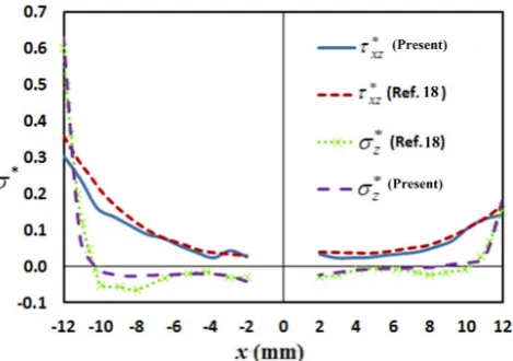
This joint was subjected to axial force ofP0= 24kN and transverse pressure ofP0 = 500kPa. Fig. 4 com-pares the adhesive layer peel and shear stress diagrams obtained from the presented finite element solution with the results presented in Ref. [18]. It can be seen that the maximum difference between stress distribu-tion diagrams obtained from the simuladistribu-tion with those presented in Ref. [18] is about 13%for the peel stress
and 16%for the shear stress.
In the second case, a comparison was carried out between the axial displacement of the hybrid single lap adhesive layer, obtained from the finite element mod-elling, with the experimental and numerical results in Ref. [22]. In Fig. 5, schematics of the hybrid joint and in Table 4, the geometry of this joint are presented.
Fig. 4. Comparison of obtained shear and peel stress distribution with the results of Ref. [18].
Table 4
Geometry of hybrid joint specimen [22].
Part Dimensions
Composite adherend Lf = 85mm,Lg= 30mm,
W1= 28mm,t= 4.39mm
Adhesive layer La= 32mm,Wa= 28mm,
ta= 0.51mm
Fig. 5. Schematics of hybrid joint specimen [22].
Here Adherends are laminated composite with car-bon fiber of Cytec 5320. The mechanical properties of composite adherends and steel bolt are shown in Table 5. Adhesive layer is epoxy EA 9361 with the stress-strain diagram as shown in Fig. 6.
Table 5
Mechanical properties of composite adherends and steel bolt and nut [22].
Part Dimensions
Composite adherend
E11= 141GPa,
E22=E33= 9.7GPa,
G12=G13= 5.1GPa,
G23= 3.4GPa,
ν12=ν13= 0.33, ν23= 0.44
Bolt and nut E=205GPa,ν= 0.3
Fig. 6. Stress-strain diagram of epoxy EA 9361 [22]. In Fig. 7, the diagram of axial displacement in terms of axial force in the hybrid single lap adhesive layer is compared with the experimental and numerical results in Ref. [22]. It can be seen that the maximum difference between the experimental results and pre-sented simulations is 4.5%. Again, a very good agree-ment was achieved with the results of the present so-lutions and the results of Ref. [22].
5. Hybrid Single Lap Joint
In the first step, to select appropriate elements number, for modeling of hybrid single lap joint, the convergence behavior was examined. For this aim, by decreasing element size (increasing element numbers), the sensi-tivity of the hybrid single lap joint on the maximum magnitudes of total displacement, axial stress, and ad-herend failure criteria were investigated. In table 6, the results of convergence study of the joint subjected to an axial force of 1300 N on the free side are presented.
Fig. 7. Comparison between the axial displacements vs. axial force obtained from the finite element mod-eling with the experimental and numerical results in Ref. [22].
It is seen that in the 3rd case, the maximum mag-nitude results of: total displacement, axial stress and failure criteria are very close to the 4th case, therefore the 3rdcase with 7826 3-D structural solid elements was selected for the modeling of hybrid single lap joint.
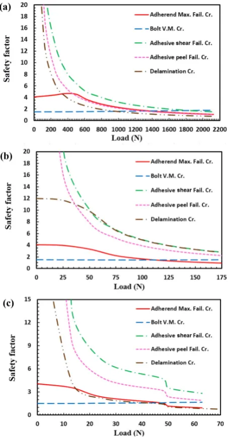
In the next step, failure analysis of hybrid single lap joint in accordance with the method described in the previous section for each axial, shear and bending loads were performed. Fig. 8 illustrates the safety factors
variation in bolts, composite adherends, and adhesive layers for different failure modes (until happening of failure) subjected to three described load cases.
It is seen that in the single lap hybrid joint the pre-tension and its torque is the dominant factor in creation of bolt stresses. The results of Fig. 8a indicates that in the case of axial load, the hybrid single lap joint de-laminated atFa= 1625N and peeling of adhesive layer is happened at 2125N, where the adherends of similar adhesive joint delaminated at axial load of 1040N and the adhesive layer failed at 2000N. Therefore, in the case of axial load, the replacement of hybrid single lap instead of adhesive lap joint caused 56%increase in the load bearing capacity.
According to Fig. 8b, it is observed that the hy-brid single lap joint subjected to shear force was failed in its adherends at Fsh = 175N and peeling adhesive failure occurred at the load magnitude of 390N, while the failure load of similar adhesive joint did not change significantly.
The results of Fig. 8c revealed that in the case of bending load, the adherend failure of hybrid single lap joint occurred at Fb = 63N, where the similar adhe-sive joint delaminated at bending load of 58N. Here the weight gain due to replacement of hybrid single lap joint instead of adhesive joint is 26%. Therefore only in the case of axial load, the replacement of adhesive joint with the hybrid bonded-bolted joint is strongly recommended.
6. Hybrid Double Lap Joint
In Table 7, the convergence study of the hybrid double lap joint subjected to the axial load of 2500N on the free side are presented. Here the convergence study results are: maximum magnitudes of total displace-ment, bolt von-mises stress, adhesive peel stress and adherend failure criteria in terms of element numbers.
Fig. 8. Factor of safeties in bolt, composite adherends and adhesive layer for different failure modes in hy-brid single lap joint subjected to a) Axial, b) Shear, c) Bending loads.
Table 6
Convergence study of hybrid single lap joint.
Case Element numbers σt−max(mm) σx−max(MPa) Max. Failure Cr.
1 1233 5.85 130.77 0.458
2 3953 5.81 148.6 0.618
3 7826 5.874 169.6 0.56
4 10478 5.858 170.27 0.546
Table 7
Convergence study of hybrid double lap joint.
Case Element numbers σt−max(mm) σV.M−Bolt(MPa) σpeel−max(MPa) Max. Failure Cr.
1 7427 0.054 6.43 79.3 0.7
2 15023 0.054 6.86 85.5 0.71
3 18297 0.056 7.20 87 0.77
It can be seen that the 3rd case results are very close to the results of the 4th case. Therefore the 3rd case with 18297 3-D structural solid elements was se-lected for the finite element modeling of hybrid double lap joint.
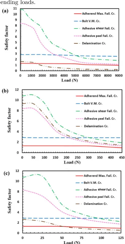
Subsequently, the failure analysis of hybrid double lap joint subjected to axial, shear and bending loads were carried out. In Fig. 9, the safety factors variation in bolts, composite adherends, and adhesive layers due to common failure modes of hybrid double lap joint subjected to axial, shear and bending loads are respec-tively presented.
According to Fig. 9a, the delamination of hybrid double lap joint subjected to axial load originated at
Fa = 2000N. Then, the peeling of adhesive layer oc-curred at axial load of 10000N. It is noticeable that the failure load of similar adhesive double lap joint did not change significantly.
The results of Fig. 9b, showed that the hybrid dou-ble lap joint subjected to shear force failed at Fsh = 450N due to adherend failure of uni-directional carbon epoxy lamina, while the failure of adhesive double lap joint initiated at shear load of 390N, due to adherend delamination. It is shown that, in the case of shear load, the replacement of adhesive joint by hybrid joint leads to only 15%increase in the load bearing capacity. Fig. 9c reveals that in the case of bending load, the adherend delamination of hybrid double lap joint oc-curred at Fb = 75N, that showed no increasing in the bending load capacity with respect to double lap adhe-sive joint. Due to the weight gain of 16%resulted from replacement of the hybrid double lap joint instead of the adhesive joint, it was concluded that this replace-ment is not economical for all axial, shear and bending load cases.
Finally, Table 8 compares the difference in the safety factors between hybrid single lap and hybrid double lap joints in terms of applied axial, shear and
bending loads.
Fig. 9. Safety factors in bolt, composite adherends and adhesive layer due to common failure modes in hy-brid double lap joint subjected to a) Axial, b) Shear, c) Bending loads.
Table 8
Comparison of the difference in the safety factors between hybrid single lap and hybrid double lap joints in terms of applied axial, shear and bending loads.
Axial Shear Bending
Load (N)
F.S (S.L)
F.S (D.L)
Diff. (%)
Load (N)
F.S (S.L)
F.S (D.L)
Diff. (%)
Load (N)
F.S (S.L)
F.S (D.L)
Diff. (%)
Pre load 1.32 1.36 3 Pre load 1.32 1.36 3 Pre load 1.32 1.36 3
250 1.31 1.35 3 50 1.31 1.35 3 25 1.15 1.33 16
500 1.22 1.31 7 100 1.2 1.34 12 50 1.08 1.30 21
750 1.11 1.30 17 150 1.09 1.33 22 63 0.86 1.14 33
1000 1.01 1.29 28 200 0.94 1.33 41 75 0.48 0.99 106
1250 0.93 1.29 39 300 0.43 1.31 204
1500 0.87 1.26 45
1750 0.81 1.05 30
2000 0.76 0.91 20
7. Conclusions
In this paper, the failure analysis of hybrid single and double lap joints with laminated composite adherends subjected to axial, shear and bending loads was carried out. For this aim, Ansys Workbench finite element software was employed to simulate hybrid composite single and double lap joints, three-dimensionally.
At first, by comparing the simulation results with those provided by other researchers, the validity and accuracy of the simulation method was confirmed. Then the convergence study was carried out for selec-tion of proper element numbers. Finally, each of single lap and double lap hybrid joints subjected to time de-pendent axial, shear and bending loads and the magni-tudes of failure load and failure mode of each case were studied. The numerical results of the present research reveal the following main conclusions:
(a) In all hybrid lap joints (subjected to each of these three load cases or their combinations), the dom-inant factor in creation of stresses and failure of bolts is pre-tension and its pre-torque.
(b) Single lap and double lap joints under shear (Fsh) and bending (Fb) loads have significant moment arm. It causes a considerable increase in the amount of displacement and stress components and decrease in the magnitude of safety factors. This event is intensified for the case of bending loads that have low moment of inertia and long bending arm simultaneously.
(c) In the case of single lap joint subjected to axial load, the replacement of hybrid bonded-bolted joint instead of adhesive joint leads to significant increase of 56% in the load bearing capacity of the joint.
(d) In the case of hybrid double lap joint, the replace-ment of adhesive joint with the hybrid bonded-bolted joint does not cause significant increase in load bearing capacity. Therefore, in such a case, the replacement of the hybrid joint instead of the adhesive joint, due to weight gain created by the addition of bolt and nut, is not economical and justifiable.
Acknowledgements
This work was supported financially by the research funding of Islamic Azad University.
References
[1] C.T. Sun, B. Kumar, P. Wang, R.D. Sterkenburg, Development of improved hybrid joints for compos-ite structures, Purdue University, USA, 1-20.
[2] O. Volkersen, Die nietkraftverteilung in zug-beanspruchten niet ver bindungen mit konstan-ten lashenquers chnitkonstan-ten, Luftfahrt-Forschung., 15 (1938) 41-47.
[3] L.J. Hart-Smith, Adhesive bonded scarf and stepped lap joints, Douglas Aircraft Company, NASA, USA, CR 112235 (1973) 1-115.
[4] L.J. Hart-Smith, Adhesive bonded single lap joints, Douglas Aircraft Company, NASA, USA, CR 112236 (1973) 1-123.
[5] L.J. Hart-Smith, Adhesive bonded double lap joints, Douglas Aircraft Company, NASA, USA, CR 112237 (1973) 1-105.
[6] R.D. Adams, J. Coppendale, N.A. Peppiatt, Fail-ure analysis of aluminum-aluminum bonded joints, J. Adhes. Appl. Sci., London, 2 (1978) 105-119. [7] J.A. Harris, R.A. Adams, Strength prediction of
bonded single lap joints by non-linear finite ele-ments methods, Int. J. Adhes. Adhes., 4(2) (1984) 65-78.
[8] A.E. Bogdanovich I. Kizhakkethara, Three dimen-sional finite element of double lap composite ad-hesive bonded joint using submodeling approach, Compos. Part B: Eng., 30(6) (1999) 537-551. [9] Y.A. Bahei-El-Din, G.J. Dvorak, New design of
ad-hesive joints for thick composite laminates, Com-pos. Sci. Technol., 61(1) (2001) 19-40.
[10] F. Mortensen, O.T. Thomsen, Analysis of adhe-sive bonded joints: a unified approach, Compos. Sci. Technol., 62(7-8) (2002) 1011-1031.
[11] E. Selahi, M. Tahani S.A. Yousefsani, Analytical solutions of stress field in adhesively bonded com-posite single-lap joints under mechanical loadings, Int. J. Eng., 27(3) (2014) 475-486.
[12] E. Selahi, M.H. Kadivar, Non-linear analysis of adhesive joints in composite structures, Int. J. Ad-van Des. Manuf. Technol., 9(1) (2016) 101-110. [13] E. Selahi, Elasticity solution of adhesive tubular
joints in laminated composites, with axial symme-try, Arch. Mech. Eng., 3 (2018) 441-456.
[14] W.S. Chan, S. Vedhagiri, Analysis of composite bonded/bolted joints used in repairing, J. Compos. Mater., 35(12) (2001) 1045-1061.
[15] G. Kelly, Load transfer in hybrid (bonded/bolted) composite single-lap joints, Compos. Struct., 69(1) (2005) 35-43.
[17] R. Matsuzaki, M. Shibata, A. Todoroki, 2008, Im-proving performance of GFRP/aluminum single-lap joints using bolted/co-cured hybrid method, Compos. Part A: Appl. Sci. Manuf., 39(2) (2008) 154-163.
[18] A. Barut, E. Madenc, Analysis of bolted–bonded composite single-lap joints under combined in-plane and transverse loading, Compos. Struct., 88(4) (2009) 579-594.
[19] C.T. Hoang-Ngoc, E. Paroissien, Simulation of single-lap bonded and hybrid (bolted/bonded) joints with flexible adhesive, Int. J. Adhes. Adhes., 30(3) (2010) 117-129.
[20] N. Duc Hai, H. Mutsuyoshi, Structural be-havior of double-lap joints of steel splice plates
bolted/bonded to pultruded hybrid CFRP/GFRP laminates, Constr. Build. Mater., 30 (2012) 347-359.
[21] S. Venkateswarlu, K. Rajasekhar, Modelling and analysis of hybrid composite joint using FEM in Ansys, IOSR J. Mech. Civ. Eng., 6(6) (2013) 1-6. [22] K. Bodjona, K. Raju, G.H. Lim, L. Lessard,
Load sharing in single-lap bonded/bolted compos-ite joints, Part I: Model development and valida-tion, Compos. Struct., 129 (2015) 268-275.
[23] Composite materials engineering data, ANSYS Workbench V. 16, ANSYS Incorporation (2014). [24] Nonlinear contact analysis techniques using
AN-SYS, Mechanics Development Group, ANSYS In-corporation.

![Fig. 6. Stress-strain diagram of epoxy EA 9361 [22].](https://thumb-us.123doks.com/thumbv2/123dok_us/8954964.1864332/6.595.46.283.390.655/fig-stress-strain-diagram-epoxy-ea.webp)