SEMIAUTOMATION OF IRRIGATED BASINS AND BORDERS:
III. CONTROL ELEMENTS AND SYSTEM OPERATION
A. S. Humpherys
ABSTRACT. Irrigation application duration is an important factor influencing surface irrigation efficiency. Most methods of semiautomatic timing and control use mechanical timers for (1 ) direct gate release by the timer, and (2) timers designed for use with electrical components such as solenoid or electric motor-actuated releases. A trip-cord gate release system and water sensors were also used to semiautomate irrigation. The trip-cord system uses the energy of an opening or closing gate to either open or close other gates in the operating sequence. Semiautomatic gates, described in articles I and II of this series, and their associated controls were tested on a basin and three border irrigation systems on two farms during a five-year period. The semiautomatic controls provided operator convenience and reduced water and labor
use. Keywords. Irrigation, Semiautomatic, Control, Timers, Trip-cord
I
rrigation application time is an important factor influencing surface irrigation efficiency. Timers are normally used to initiate semiautomatic irrigations and to determine application duration. They also activate
mechanical releases or other secondary devices for tripping
gates at predetermined times.
Semiautomatic systems and controls require manual attention to reset gates and/or controls to their pre-irrigation positions. Since irrigators normally keep close watch on their fields, they are usually available to perform the manual functions of a semiautomated system. However, they may not be available at the precise time that basin or border irrigation sets need to be changed, nor at night, and they need systems that can be programmed to make several unattended set changes. Semiautomatic systems can sometimes be an advantage over full automation because they require irrigator presence periodically in the field.
Irrigation timing devices including mechanical timers or clocks, both to time irrigation duration and to release gates, were reported previously (Reynolds, 1968; Humpherys, 1969; Hart and Borelli, 1970; Haise and Hall, 1971; Evans, 1977; Taylor et al., 1982; Humpherys, 1986). Electronic and electric multi-station controllers are widely used for sprinkler and microirrigation control, but their use in surface irrigation is very limited. They require AC line voltage, which is usually not available in surface irrigated fields, and they also require communication to individual control stations, which is costly and cumbersome for multiple irrigation sets. Battery-powered, portable electronic timers are not generally commercially available for surface irrigation systems.
Article has been reviewed and approved for publication by the Soil and Water Div. of ASAE. Presented as ASAE Paper Nos. 87-2736 and 88-2583 and in part at the Irrigation Association, Third National Irrigation Symposium, 28 October to 1 November 1990, Phoenix, Ariz.
Names or products or companies are shown for the benefit of the reader and do not imply endorsement or preferential treatment of the company or products shown by the USDA-Agricultural Research Service. The author is Allan S. Rumpherys, ASAE Member Engineer, Agricultural Engineer, USDA-Agricultural Research Service, Soil and Water Management Research, Kimberly, Idaho.
Water or soil moisture sensors located near the lower end of a field can be used to terminate irrigation. These compensate for changes in advance time through a field from one irrigation to the next.
Many basins and borders are irrigated from multiple turnouts in the side of a supply ditch. Since water flows from all of the outlets of a group during irrigation, the outlet control gates must operate simultaneously. The trip-cord gate release system described in this article accomplishes this purpose. Two previous articles (Humpherys, 1995a, b) describe single- and dual-function semiautomated gates, operated by the trip-cord system. The purpose of this article is to describe several methods of releasing or controlling semiautomatic irrigation gates, including the trip-cord system for releasing multiple turnout gates. Field tests and system operation in a level basin and three border irrigation systems are also described.
SEMIAUTOMATIC CONTROL ELEMENTS
INDIVIDUAL GATE RELEASES
Portable timers mounted on individual gates, or structures, or housed in enclosures that can be moved from gate-to-gate during an irrigation were used to release gates. These include direct-release, solenoid-release, and electric-motor-release timers.
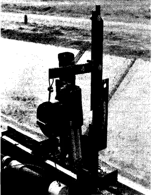
Direct-release. Timers for direct-release are mechanical and include 24-h timers and alarm clocks (Taylor et al., 1982). For those used in this study, the gate's release mechanism is restrained by a pin on the timer which is retracted at zero time and allows the gate to either open or close. This type of timer is shown in figure 1.
Solenoid-release. This gate release uses a 24-h mechanical timer (Frank W. Murphy Manufacturing, Inc., Tulsa, Okla.) with built-in electrical contacts that close when the timer trips at the end of a preset time period. The gate release is actuated by an intermittent, or pulse duty, 6-V electric solenoid (Deltrol Controls, Milwaukee, Wis., and Guardian electric Mfg. Co., Chicago, Ill.) energized from a 22,000 pfd or larger electrolytic capacitor when the
Timer NC
= 10 r2.
R2 =
600
oC = 22,000 11F. or larger
SCR = 2N6394 or equivalent
= SOLENOID
L
Figure 2–Electrical diagram for a timer-controlled solenoid driver.
Figure 1–Direct-release, mechanical timer and gate release, or latch, for a dual-flinction combination gate.
timer trips. Since it is only energized momentarily, a 6-V solenoid is used with 12 V to provide a stronger pull force. In earlier studies, the capacitor discharged directly through the timer's electrical contacts. However, arcing caused by the high discharge current burned the contacts and caused them to fail. This problem was solved by discharging the capacitor through a 2N6394, or similar, silicone-controlled rectifier (SCR) which functions as an electrical switch. Only a small, 15 ma trigger current for the SCR goes through the timer's contacts. The electrical diagram for operating the solenoid from a 12-V battery is shown in figure 2. When the timer trips, the SCR trigger circuit is completed, and the SCR changes from a nonconducting to a conducting state to energize the solenoid which actuates the gate release.
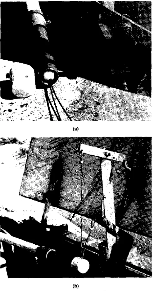
The timer and its electrical components to operate a single gate were mounted in an enclosure as shown in figure 3a. Dual-function gates require two timers with their associated SCRs and capacitors (fig. 3b). A pigtail with a quick-connect coupler is used to connect the tinier unit to the solenoid to facilitate portability. Both rechargeable and lantern-type 12-V batteries were used. A typical solenoid-actuated gate release is shown by the diagram in figure 4. A cover for the solenoid, formed from a short piece of ABS pipe, is not shown.
An electronic digital count-down timer currently being developed can drive a solenoid in the same manner as described above (Irrigation Systems Co. of Western Colorado, Fruita,
(a)
(b)
Gate Latch Arm
FULL SCALE
Gate Suspension Cord
C Pivot
Upright
Solenoidi
r Mfg Bolt (2)
C
Pivot
C Pin
Mfg Plate
3 X 51 X 121 mm
(1/8 X 2 X 4 3/4 in.)
Gate
Post
2 mm
Stop
Latch Release Arm
Gate Upright Post
Latch Release Arm
C Mfg Bolt (2)
Plastic Rub Block
cur y Switch
Motor N119 Bolt (2) Gate Latch Finger
N C Mercury Switch Mounting Plate Gate Latch Finger FULL SCALE
Gate Suspension Cord (L Pivot & Spacer
NC Mercury Switch Motor & Cain
Spring
NO Mercury Switch Mounting Plate
Plastic Rub Block
Gate Upright Post (a)
Latch Release Arm
l
mm X 127 rnm(3/4 in. X 5 in.)
Figure 4-Sketch of a typical solenoid-actuated gate release.
Pin
(b) Electric Motor Release. This gate release (fig. 5) uses
the same 24-h mechanical timer as the solenoid release to control a small 1 rpm gearmotor. A cam attached to the output shaft of the 3 VDC motor (Hankscraft Motors, Division of Gerber Products Co., Reedsburg, Wis.) actuates the latch release arm as it turns. Two enclosed, SPST mercury switches (7MP1 -2), MicroSwitch, Division of Honeywell, Freeport, Ill.) mounted on the gate latch finger and the latch release arm (fig. 5) control starting and stopping of the motor. The motor-driven gate release device is assembled on a mounting plate which is positioned as needed and bolted to the gate like that for the solenoid release. The timer and two D-size batteries are mounted in a separate enclosure.
Costs. Representative and comparison costs for timer-controlled releases and their associated components are shown in table 1. The timer unit for a motor-driven gate release costs less than that for a solenoid-actuated release because it does not require an SCR or capacitor and uses low-cost D batteries instead of a lantern battery. However, its gate release unit costs more than the simple solenoid release. Thus, for an irrigation system that has many turnout gates, the solenoid-operated releases cost less. Even though its timer unit costs more, it is portable and a relatively small number are required. When the timers are not moved and the enclosure cost is small, or for relatively few gates, the motor-actuated gate release may be preferable. Functionally, they are the same; the total costs, as shown in table 1, are not significantly different. Costs are not shown for direct-release timers because the author is not aware of their current availability for irrigation.
Figure 5-Motor-driven gate release: (a) for a drop-closed gate, and (b) for a drop-open gate.
Table 1. Comparative costs for timer-controlled solenoid- and motor-driven gate release units
Component Solenoid-driven Motor-driven
Gate release Solenoid $ 11.00 3 V motorlcam $ 16.00
Hg switch (2) 12.00
Switch mtg. clip (2) 5.00
Subtotal 11.00 33.00
Timer unit 12 V battery
15.00 Batteries (2) 1.5 V 5.00
Capacitor 8.00 Battery holder 200
SCR 4.00 Enclosure, tabor, etc.
15.00
Enclosure, labor, etc.
15.00 Mechanical timer 88.00
Mechanical timer
88.00
Subtotal 130.00 110.00
Total Cost* $ 141.00 $143.00
Gate Latch Cable Connection Activating Gate
Gate Hinge C.)
SOLENOID-RELEASE SYSTEM FOR MULTIPLE GATES
Turnout gates were installed in a pilot installation on a cooperator's farm for a level basin system having four turnouts into each 4 ha (10 acre) basin. The four gates were controlled simultaneously by a single timer and released by electric solenoids, one at each gate, which were wired
together. A solenoid driver was required for each solenoid
(fig. 2). Distance between gates was not a factor because the capacitors could be charged over a period of time and the trigger signal current to each SCR was so small that line loss was negligible.
The SCR and capacitor of each solenoid driver were encased in a 20 cm (8 in.) long, 50 mm (2 in.) diameter PVC pipe section mounted on the gate. The system worked well until the interconnecting wires were burned when the farmer burned his ditchbank weeds the following year. If this type of system is used, the wires must be installed in a buried conduit. The system was abandoned in favor of the trip-cord gate release system, which also cost less.
TRW-CORD GATE RELEASE SYSTEM
This system was developed to release multiple gates simultaneously by utilizing the energy of an opening or closing gate to release the next gate(s) in the operating sequence. It was used to control 23 turnout gates in a level basin system near Delta, Utah, and 99 gates in three border systems at Eskdale, Utah. The system consists of a 3 mm (118 in.) diameter black polypropylene trip cord installed in a 25 mm (1 in.) or a 19 mm (3/4 in.) diameter, 1400 kpa (200 psi) PVC pipe buried along the ditchbank. Approximately 40 to 70 cm (16 to 28 in.) of 1.2 mm (3/64 in.) diameter, vinyl-covered, stainless steel cable is attached to each end of the cord by means of aluminum clamp sleeves and cable thimbles as shown by the diagram in figure 6. The system's components are described in table 2. The cable on one end is permanently attached to the activating gate with a clamp sleeve. The other end is attached to the latch of the activated gate with an adjustable shaft collar and set screw. The UV treated, PVC, 90° electrical conduit elbows and short conduit extensions are attached to the ends of the buried PVC pipe to cover and protect the cord and cable (figure 7). The elbows provide a smooth curve for changing directions. EMT and flexible
Figure 6-Diagram of a trip-cord gate release system (see table 2 for a description of the part numbers).
electrical conduit bent to the desired shape were used on earlier installations instead of the PVC electrical conduit fittings, but they were not as satisfactory and were more difficult to install. The 19 mm (3/4 in.) diameter electrical conduit extensions and elbows are not large enough for two cord/cable connections to pass. Therefore, the conduit extensions for dual-function_ gates, which require two cords, were made long enough so the cable connections could be staggered inside. Either a cable guide with a roller, or a short-radius 13 mm (1/2 in.) PVC conduit elbow, is attached to the latch-activating end of the cord conduit extension. The available vertical space is not sufficient on some gates for an elbow at the point where the cable attaches to the gate latch. Hence, the cable guide assembly shown in figure 8 is used on these gates. The guide consists of a delrin roller mounted on a bronze shaft near the end of a 100 mm (4 in.) length of 19 mm (314 in.) diameter PVC electrical conduit pipe. A cap with a 3 mm (1/8 in.) guide hole on top fits over the end of the pipe and holds the roller shaft in place. The cap slips over the end and is not cemented.
A 20 cm (8 in.) deep trench for the buried pipe was hand dug. This depth was adequate if the pipe ends were anchored with a mound of concrete. Many mice in the ditchbank did not bother the pipe. However, a larger diameter pipe [35 to 50 mm (1 1/2 to 2)] may be needed to prevent gopher damage. The polypropylene cord was installed inside the buried pipe by using a 13 mm (1/2 in.) diameter PVC pipe as a long rod. One end of the cord was placed in a notch in the end of the rod pipe, and the "rod", with cord attached, was pushed through the buried pipe. The cable and cord connections were made beginning at the "pull" end of the cord where the cable is permanently attached to the activating gate.
In operation: (1) the first gate of a group or pair is released by a timer, or by an electric solenoid controlled by a timer or sensor, (2) a trip cord attached to that first gate is pulled by the opening or closing action of the gate, and (3) the motion thus generated is transferred by the trip cord to the latch of the next adjacent gate in the series to either open or close that gate. If there are more than two gates in a group that operate simultaneously, steps 2 and 3 are repeated to the last gate of the group. This system greatly reduces the number of timers required. Instead of using two timers on each dual-function gate—one to begin irrigation and one to end irrigation—only one timer is required for each irrigation set regardless of the number of simultaneously operating gates used. A single timer, or sensor, begins irrigation of its associated set and, at the same time, irrigation of the previous set or group of gates is terminated when its gates are closed by action of the opening gates of the subsequent set. Thus, this system assures that the gates of a subsequent set are open before the gates of a previous set are closed. This fail-safe feature is significant since it avoids problems that could occur if all of the gates in the system were closed at the same time.
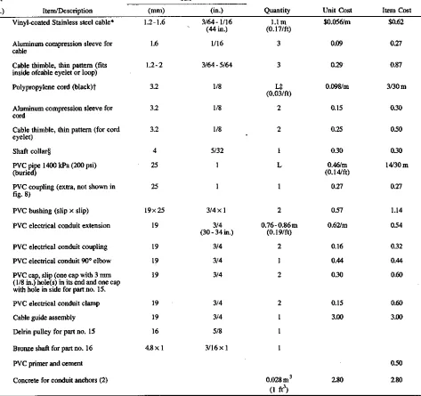
Table 2. List of materials, part descriptions, and costs for one panel or section of a single trip-cord gate release system as shown in figure 6
14 15 16
17 18
19
Size
Quantity Unit Cost Item Cost
Item/Description (mm) (in.)
Vinyl-coated Stainless steel cable* 1.2 -1.6 3/64 - 1/16 1.1m $0.056/m $0.62 (44 in.) (0.17/f-t)
Aluminum compression sleeve for cable
1.6 1/16 3 0.09 0.27
Cable thimble, thin pattern (fits inside ofcable eyelet or loop)
1.2 - 2 3/64-5/64 3 0.29 0.87
Polypropylene cord (black)t 3.2 118 0.098/m 3130m
(0.03/ft) Aluminum compression sleeve for
cord
3.2 1/8 2 0.15 030
Cable thimble, thin pattern (for cord eyelet)
3.2 1/8 2 0.25 0.50
Shaft collar§ 4 5/32 1 0.30 030
PVC pipe 1400 kPa (200 psi) 25 0.46/m 1480 m
(buried) (0.14/ft)
PVC coupling (extra, not shown in fig. 8)
25 1 1 0.27 0.27
PVC bushing (slip x slip) 19x25 3/4 xl 2 0.57 1.14
PVC electrical conduit extension 19 3/4 0.76-0.86m 0.62/m 054
(30 - 34 in.) (0.19/ft)
PVC electrical conduit coupling 19 314 2 0,16 0,32
PVC electrical conduit 90° elbow 19 3/4 1 0.44 0.44
PVC cap, slip (one cap with 3 mm 19 3/4 2 030 0.60
(1/8 in.) hole(s) in its end and one cap with hole in side for part no. 15.
PVC electrical conduit clamp 19 3/4 2 0.15 0.60
Cable guide assembly 19 3/4 1 3.00 3.00
Delrin pulley for part no. 15 16 5/8 1
Bronze shaft for part no. 16 4.8 x 1 3/16 x 1 1
PVC primer and cement 0.50
Concrete for conduit anchors (2) 0.023 2.80 2.80
(1 ft3) Part
(no.) 1
2
3
4
5
6
7 8
8a
9 10
11 12 13
* Stainless steel cable and associated items can be obtained in the relatively small quantities required for a trip-cord system front McMaster-Carr Supply Co., 9630 Norwalk Blvd., Sante Fe Springs, CA 90670 (telephone 213-695-2449).
t Polypropylene cord can be obtained from Crow Rope Company, Main Street, Box 345, Warren, ME 04684 (telephone 207-273-2424). L - Distance between irrigation turnout structures.
§ G&G Mfg. Co., Omaha, NE 68108 (telephone 402-453-9595).
WATER SENSOR AND FEEDBACK CONTROL SYSTEM
A water sensor control system was tested to provide feedback control for semiautomatic irrigation of basins and borders (Humpherys and Fisher, 1995). The sensor, placed about three-fourths of the basin length downfield, provided a signal via wire to a station controller to stop irrigation. Infrared (IR) telemetry could also be used for communication instead of the wire. The station controller actuated a release to close an irrigation gate similar to that described previously for a timer-controlled solenoid release.
SYSTEM CONTROL AND FIELD OPERATION Semiautomatic gates, described in two previous articles (Humpherys, 1995a, b), and their associated controls were
tested in a near-level basin system and in three border irrigation systems. The gates and control system were developed over several years of testing during which a number of modifications were made. The operational logic for these systems is different one from the other and provided an opportunity to test the trip-cord gate release system under different conditions and operating sequences. These experimental systems also illustrated the potential use and flexibility of a semiautomatic system and its controls.
BASIN SYSTEM
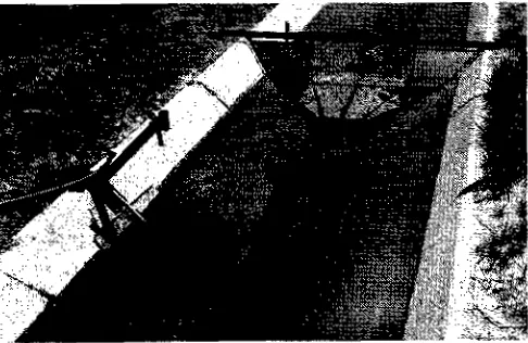
Figure 7-Photo to illustrate relative positioning of cables and conduit at the "pull" end of a trip-cord system.
(a)
(b)
Figure 8-Cable guide assembly with a roller for a trip-cord gate release system: (a) view with roller exposed, and (b) complete assembly with cables attached to gate latches.
leveled with laser-controlled equipment. The field is served by a concrete-lined supply ditch which has zero slope and a 0.06 m (0.2 ft) drop at midfield. The ditch serves four basins on each side with a supply stream which varies from 225 to 300 L/s (8 to II efs). The irrigation stream is diverted into each basin through four outlets in the side of the ditch. Alfalfa is the principal crop grown; thus, all basins have the same irrigation schedule and can be irrigated sequentially. This system prompted the development of the trip-cord gate release system because the four gates of each basin need to open or close simultaneously. The basin system tests were conducted on the four basins upstream from midfield which operated as one subsystem. Two basins in the downstream section of ditch were used to test different versions of the experimental gates.
Basins on the west side of the ditch are lower in elevation than those on the east side and have pipe outlets near the bottom of the ditch. The two upstream basins (1W, 2W) on the west side were equipped with pipe-type drop-closed gates (Humpherys, 1995a). Outlets near the top of the ditch on the opposite side were equipped with rectangular drop-closed gates which were high enough in the side of the ditch to prevent outflow during irrigation of the low elevation basins on the west side. A center-of-pressure checkgate (Humpherys, 1991) was positioned in the supply ditch between the first and second pair of basins while a jack gate was located in the ditch at midfield (Humpherys, 1995b). Irrigation from both sides of a supply ditch is unusual, but this situation simplified automation and allowed use of lower-cost single function gates in all turnouts rather than having the more costly dual-function gates on one side.
All of the gates were manually reset prior to an irrigation. During irrigation, water was first diverted to low-elevation basin 1W. When water reached a sensor located about three-fourths of the basin length downfield, a signal was generated to close the first gate, which closed the other three gates in the group with a trip-cord gate release system to terminate irrigation of that basin. The water level in the supply ditch then rose and water flowed through turnouts on the opposite side of the ditch into basin
C - Malkin Scam.- CaItrolvr 2C - Two•Slosan Samar Caemniv IT • 5gs Sialion
T.e.-Figure 9-Schematic diagram of the level basin irrigation system for testing semiautomatic gates and timers.
lE where the irrigation sequence was repeated. When the first two basins were irrigated, the center-of-pressure checkgate opened to begin irrigation of the next pair of basins where the same operational sequence was repeated.
The polypropylene cord inside of metal EMT conduits was inadvertently melted when weeds on the ditchbank were burned. This could also occur with the PVC conduit fittings presently used and caution is needed when ditch banks are burned. Weeds around the turnout gates and their controls should be controlled by herbicides rather than by burning.
BORDER SYSTEMS
Semiautomatic gates for timer control were installed in three border subsystems planted to barley and/or alfalfa.
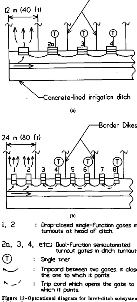
Field Lateral No. 1. This system consists of an existing 268 m (880 ft) long concrete-lined ditch with a slope of 0.08% and 22 concrete pipe turnouts of the type shown in figure 10. The pipe turnouts, spaced 12 m (40 ft) apart, are equipped with single-function drop-closed gates. Because the ditch is sloped, a center-of-pressure checkgate was installed just downstream from every second turnout. Borders 12 in (40 ft) wide were irrigated from one turnout with 120 Lis (4.3 cfs) from wells. The border width will be increased later to 24 m (80 ft) when the supply stream is increased by the addition of another well. Each wide border will then be irrigated from two turnouts. Each gate was
released from its manually reset, open position by a direct-release, mechanical timer. The portably mounted timers were moved from one group of gates to another during an irrigation. A trip-cord gate release system was installed for subsequent use with the 24 m (80 ft) full width borders.
In the final system, the upstream gate of each full size border will be tripped by a timer. The second gate of a pair will be released by trip cord. When the gates close, the water level in the ditch rises and trips the checkgate which opens to begin irrigation of the next downstream border where the operation is repeated. Currently, with the half-size borders, the system is cycled twice during each irrigation with every second border irrigated each time because only one turnout at a time is used. The system was operated manually during the first two years because timers were not available and the irrigator wanted to be present to prevent dike overtopping and washout. The field was rough prior to leveling, and afterwards the temporary dikes were unstable. The system performed well the third year except
Figure 10-Photo of gates in lateral no. 1 border Irrigation system.
several timers malfunctioned due to wind-blown dust. All enclosures will be resealed and precautions taken to prevent dust entry.
Field Lateral No. 3. This system consists of an existing
concrete-lined supply ditch 305 m (1000 ft) long with a slope of 0.086% and 25 rectangular outlets spaced 12 m (40 ft) apart equipped with both dual- and single-function turnout gates. Because the head ditch is sloped, checkgates must be used. A center-of-pressure gate is installed just downstream from every fourth turnout. The gates were released by mechanical timers and a trip-cord system. The 24 m (80 ft) wide borders were irrigated in pairs with two turnouts for each border. The first two gates immediately downstream from each checkgate are single-function drop-closed gates while the next two gates are dual-function combination gates (Humpherys, 1995b) which both open and close and consist of a drop-open and a drop-closed gate mounted on the same frame. The gate immediately upstream from the ditch checkgate was equipped with two timers. These timers controlled irrigation of the two borders of a pair with the trip-cord system as illustrated in figure 11. A dual trip-cord was installed between gates corresponding to gates 4 and 3, and single cords between gates corresponding to gates 3, 2, and 1. The timers were moved between sets once each day.
Prior to an irrigation, the gates were manually reset with gates 1 and 2 open and gates 3 and 4 closed. When water was first received in the ditch, or was released from an upstream set, it flowed onto the first border of a pair through open gates 1 and 2. Irrigation of the second border began when the first timer on gate 4 tripped to open that gate. The opening action of gate 4 actuated a trip cord to open gate 3 which then closed gates 2 and 1. The second timer tripped to stop irrigation of the second border by closing gate 4, which closed gate 3. The water level in the ditch rose until the checkgate opened to release water into the next downstream set to begin irrigation of the next pair of borders. The sequence was repeated to the last set where the irrigator turned the water off.
order Dikes
24 m (80 f t)
<
oncrete-lined irrigation ditch
12 m (40 ft)
tc
oncrete-lined irrigation ditch
Drop-closed single-Function gates in turnout openings located at head of ditch and downstream from ditch checks
3-4, 7-8, etc. : Dud-
F
unctio serniautomated turnout gates in ditch turnouts Center-ofpresstre check gates in sloping ditchTurnout gate with two control timers
1-2, 5-6, etc. :
C 1 1 Cv etc.
: Trip cord to close the gate to which it points
I
t
F Trip cord to open the gate towhich it points
Figure 11–Schematic diagram illustrating the operation and control system functions for lateral no. 3, sloping-ditch border irrigation system.
SUMMARY AND CONCLUSIONS
Timers designed for use with electrical components and mechanical, direct-release timers were both used to provide on-off control of surface irrigation. The first type discharges an electrolytic capacitor through an SCR to energize an electric solenoid to actuate a gate release. This timer can also be used to control a small DC motor-actuated gate release. A trip-cord gate release system was developed to trip or release multiple gates simultaneously. The energy of an opening or closing gate is used to pull a trip cord which opens or closes other gates in the operating sequence. Thus, irrigation moves sequentially from set to set as the opening gate(s) of one set close those of the previous set. Semiautomatic gates, described in two previous articles, and their associated controls were installed and tested in a basin and three border irrigation systems during a five-year period on two farms.
The following are conclusions from the data for the field tests.
Mechanical, 24-h timers used with electrical solenoids energized by capacitor discharge through an SCR reliably and effectively controlled gate releases. The direct-release timers used in this study, which are no longer commercially available, were less reliable.
A trip-cord gate release system was an effective, reliable, and relatively low-cost system for simultaneously releasing semiautomatic gates in multiple turnouts and
order Dikes
(a)
(b)
1, 2
: Drop-closed single-fu00n gates nturnouts at head of ditch
2o, 3,
4, etc.:
Duca-Factionsennutcnated
turnout gates in ditch turnouts. Slagle
Tripcord between two gates_ it closes the one to which it points.
: Tria cord which opens the gate to which it points.
Figure 12–Operational diagram for level-ditch subsystems: (a) initially with narrow, 12 m (40 ft) wide borders, and (b) final system with 24 m (S0 ft) wide borders.
reduced the number of timers required by using an "opening" or "closing" gate to begin or terminate irrigation of an adjacent set. The 1993 cost of one section of trip-cord system for one turnout gate, including materials and installation, was approximately $50.
Once installed, a buried trip-cord system is permanent and can give many years of service with minimal maintenance. A system in use for five years is in good condition where ditchbank burning near the irrigation gates was avoided.
Weeds near irrigation gates and controls should be controlled by herbicides rather than by burning.
Tests under different operating conditions and sequencing configurations demonstrated the potential and flexibility of the semiautomatic system and controls. Irrigation time on one partially completed improved system was reduced from five to two half-days when operated manually before timers were installed.
ACKNOWLEDGMENT. The author gratefully acknowledges the cooperation of O'Dean Anderson and Howard Clayton, operators of the farms on which the field tests were conducted.
REFERENCES
Evans, R. G. 1977. Improved semiautomatic gates for cut-back surface irrigation systems. Transactions of the ASAE 20(1):105-108, 112.
Hart, W E. and 7. Boreal. 1970. Mechanized surface irrigation systems for rolling lands. Univ. of California Water Resource Ctr. Contr, 144.
Haise, H. R. and T. H. Hall. 1971. Semiautomatic timer operated
check gates for intermittent irrigation. Colorado State Univ. Exp. Station Progress Report, PR 71-3.
Humpherys, A. S. 1969. Mechanical structures for farm irrigation. Am. Soc. Civil Eng. .I. Irrig. and Drainage Div.
95(1R4):463-479.
. 1986. Automated farm surface irrigation systems worldwide. Special Pub., Int. Comm. on Irrig. and Drainage (ICED). New Delhi, India: United India Press.
. 1991. Center-of-pressure gates for irrigation. Applied Engineering in Agriculture 7(2):185-192.
. 1995a. Semiautomation of irrigated basins and borders: I. Single-function turnout gates. Applied Engineering in Agriculture 11(1):67-74.
. 1995b. Semiautomation of irrigated basins and borders: II. Dual-function turnout gates. Applied Engineering in Agriculture 1 I (1): 75- 82.
Humpherys, A. S. and H. D. Fisher. 1995. Water sensor feedback control system for surface irrigation. Applied Engineering in Agriculture 11(1):61-65.
Reynolds, W. N. 1968. Automatic-surface irrigation in Hawaii. In Proc. Am. Soc. Civil Eng. In-ig. and Drainage Div. Spec. Conf.,
201-208. Phoenix, Ariz.