MURDOCH RESEARCH REPOSITORY
http://dx.doi.org/10.1109/ICIP.1994.413395
Li, W., Xie, H. and Attikiouzel, Y. (1994) An efficient method of
volume rendering for medical slices. In: Proceedings of the IEEE
International Conference on Image Processing, ICIP 94, 13 - 16
November, Austin, Texas, USA, pp. 652-656.
http://researchrepository.murdoch.edu.au/19139/
Copyright © 1994 IEEE
Personal use of this material is permitted. However, permission to reprint/republish
this material for advertising or promotional purposes or for creating new collective
AN EFFICIENT METHOD
OF
VOLUME RENDERING FOR MEDICAL SLICES
Wunging Li
t
Hong
Xie
$
Yiunni Attikiouzel
t
t
CIIPS,
Dept of Electrical
&
Electronic
Engineering,
The
University of
Western Australia,
WA
6009,
AUSTRALIA
[email protected].
au
Computer Science Department, Murdoch University,
Murdoch,
WA 6150, AUSTRALIA
xie8cs. murdoch.edu.au
ABSTRACT
We present an efficient method for volume render- ing. This method uses a special light source - slit-light source to illuminate the volume and simulates the inter- actions of light with objects, such as light absorption, scattering and reflection.
In comparison with previous methods, our method has several advantages. This includes flexibility for im- plementation, efficiency for computation, high reality for display and easiness of parallelization. The algo- rithm can be parallelized easily either using the Data Space Subdivision method or the Image Space Subdi- vision method.
1.
INTRODUCTION
Volume visualization [l, 2, 3, 41 provides direct ap- proaches to display 3-D information in 3-D digital scenes, or volumes. Two main categories of techniques are commonly used in volume visualization: surface ren- dering and volume rendering [l, 2, 3, 41.
Surface rendering is used for visualizing the shapes of 3D objects and the spatial relationships among these objects. In this method, the surfaces of objects are first defined and modelled by polygons or other geometric primitives through segmentation or surface detection. These geometrical primitives are then rendered using the conventional computer graphics techniques for ge- ometrical objects. This method tends to lose valuable information about objects when applied to many natu- ral objects, such as trees and human tissues, which are not easily modelled by simple geometric primitives.
In contrast to surface rendering, volume rendering transforms the density information of a volume to the
gray or color intensity in the 2-D viewing srlace directly without detecting, formatting or modelling object sur- faces. It avoids the difficult segmentation process and the possible artifacts that can be introduced by the seg- mentation process. It provides a better mechanism for displaying weak or fuzzy surfaces and internal struc- tures.
In this paper, we will discuss some 0:’ the major issues with the volume rendering techniquc first. This is followed by a brief review of the previous work in this area. Then we will present our new method for volume rendering which is aimed at solving some of the major problems that have been discussed. Finally we describe some experimental results of applying our method to several sets of MRI and C T slices of human heads, which show the effectiveness of our method.
2.
PROBLEMS
OFVOLUME RENDERING
In general, A volume rendering system [2, 3, 41 can be divided into three components, i.e.
,
preprocessing, illu- mination modeling and a ray tracing algorithm. Prepre- cessing converts the original density into device and application independent values, such as tht 8 absorptioncoefficiency, color and opacity. Illuminati m modeling defines the geometry of the model and interactions be- tween the light and objects. Ray tracin: algorithm traces rays into the volume and calculates ,heir contri- butions to the viewing image according to the defined model.
There are three main problems in volume rendering: huge data volume, intensive computation, *md require- ment of high display quality
gorithms [5], the use of specialized architectures, like J?uchs/Poulton Pixel-Planes Machine, Kaufman’s Cube Architecture, Pixar/Vicom
11,
Reynolds and Goldwasser’s Voxel Processor Architecture [l, 61.Recently, parallelization of classical volume render- ing algorithms and their implementation on general purpose SIMD and MIMD machines, and on distributed systems or networked computer systems show some prospect of performance improvements [7]. However, such improvements depend heavyly on the amount of parallelism inherent in the original rendering algorithms. Unfortunately, the parallelization was not a major con- sideration when those classical volume rendering meth- ods were first proposed.
As to the requirement of high display quality, it is often desired, in many applications, that the image should provide details of objects with high reality, e.g., shadow, shading and depth cue. In surface rendering, objects are well defined and modelled. Highly qual- itative display can be normally obtained. In volume rendering, however, objects are implied in the volume data set. There is no underlying mathematical mod- els that can be used to describe them. Consequently, the quality of display mainly relies on the illumination model used for rendering.
A number of illumination models were proposed in the past [8]. Most of them are solid object surface based illumination models. They do not consider the emission and absorption of light, which are very important to visualize volume data set.
In 1986, Kijiya [9] proposed a global illumination model without limitations, restrictions or simplifying assumption. Unfortunately, no analytic mathemati- cal solution exists for his illumination equation. Ka- jiya suggested to solve the equation using Monte Carlo method. Later, several simplified models were pro- posed baaed on the Kajiya model. Some of the typical examples are Meinzer ’s Heidelberg Ray Tracing Model
[4], Blinn’s Light Reflection Function [lo], and Drebin’s and Levoy’s Ray Casting model [2, 31.
Blinn’s model requires that objects consist of ho- mogeneous material. It used one parallel light source and assumed the low albedo case. In Drebin’s and Levoy’s ray casting model, there were no emission and absorption components, hence no real shadow. In Hei- delberg model, although the emission and absorption of light were simulated for shadow and shading, the display lacked of perspective effect and depth cues be- cause of using parallel light and also extra-computation was needed for the second light source.
In this paper, we have developed an efficient method of volume rendering based on the Heidelberg ray trac- ing model but using one slit-light source. It incor-
porates provisions for parallelization and it minimizes the data swap between the main memory and disks. The algorithm is flexible enough to be implemented on micro-computers, general workstations, parallel ma- chines, and networked computers. Following sections describe our methods in details.
3. RAY TRACING MODEL
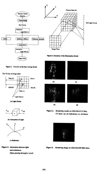
We assume that the original volume is already is0,tropic. Otherwise, interpolation may be applied to con’sert the data set into an isotropic one. Figure 1 gives an out- line of the processes involved in our ray tracing model. It consists of a preprocessing component, a con;ponent for modeling illumination, and a ray tracing algorithm associated with the illumination model.
3.1.
Preprocessing
Before rendering is taking place, the volume data val- ues must be converted into a predefined uniform for- mat. This is done in the preprocessing comJonent. Of special consideration here is the transformiltion of modality-dependent values into the standard onvs. This is accomplished by a linear transformation of voxel den- sity into the range between 0 and 1.
Other preprocessing, like adjustment or enhance- ment of the density values of certain image legions, selection of interesting objects, could also be carried out in this component.
3.2.
Illumination Model
It is composed of two parts. One is its geometry, which defines the type of light source, the geometric rcdation- ships among the light source, the volume, and the ob- server. The other is the interactions between the light and objects in volumes.
For the former, we use the slit-light source located vertical to the slice plane, as shown in Figure 2. The rendering of each slice is projected to one row on the display image. This setting brings us a number of ben- efits. With this model, it is obvious that the volume data can be loaded and rendered slice by slicrs. The model also implies the rendering process can 1)e par- allelized by data space subdivision (DSS) or bi image space subdivision (ISS).
For the latter, Kajiya [9] provided a global c escrip- tion of the interactions between light and objects. His rendering equation states that the transport in tensity of light from one surface point to another is simply the sum of the emitted light and the total light inten- sity which is scattered towards the second point from all other surface points. In his equation, each Jurface
point is thought as a new light source, the reflection and refraction of light are represented by a “geometry” term.
As there is no analytical or mathematical solution to the equation, it must be simplified before it can be implemented on computers. In our model, several simplifying assumptions have been made as did in [4].
One important assumption is that the various interac- tions of the light with objects are independent of each other. Other simplifications include the assumption of low albedo case, the omitting of the reflected and scat- tered portions in calculating the absorption, and the assumption that there is no refraction existed when light passing through the surfaces of different objects. Thus, our model simulates the following interactions, as shown in Figure 3.
e Absorption of light: when light passing through a voxel, it will be attenuated by a certain percent- age. The percentage is defined as a function of the voxel’s density, as shown in Figure 3 (a) and (b).
where, d is the voxel density after preprocessing,
I,,,
l o u t , and Iabg are the intensities of the in-cident light, the transmitted light and the ab- sorbed light respectively. fa(d) models the ab- sorption of light, called absorption function, with value range of [0,1]. It provides us ways of set- ting different absorption nonlinearly for different tissues. This setting will produce a variety of vi- sual effects, such as transparency and boundaries between different types of tissues on the display.
Absorption of light in our model produces real shadows on the final display.
e Scattering: when light hits a voxel, a portion of it will be scattered towards the observer. We as- sume that the light is scattered uniformly in all directions and the intensity of the scattered light is proportional to the intensity of the incident light at the voxel and to the function of the voxel density d, i.e.,
where f a ( d ) is a scattering function with value range of [0,1].
e Reflection: analogous to scattering, when light hits a voxel which is just on an object surface,
some of it will be reflected to the observer. In con- trast to scattering, the intensity of the reflected light depends on the position of the observer, or the viewing direction. This interaction give us a real shading on the display.
Phong shading is used to model tht reflection of the light. Just as scattering, the portion of the light reflected to the observer is pr Iportional to the incident light.
where I p e j is the reflected intensity, I, is the am- bient intensity, I d i j is the diffusely reflected in- tensity, Ispe is the specularly reflec ,ed intensity, and Iin is incident intensity.
ii
is the normalized vector of the object’s :urface,L
is the direction of the incident light,V
is the view ng direction,p is the exponent that varies with the glossiness of the surface.
To avoid an extra description or iegmentation of the volume, we estimate the ob*ect’s surface normal based on the intensities of neighbouring voxels, i.e., the intensity gradient i:, used as the normal of the surface at a given point [ll]
.
3.3. Ray Tracing Algorithm
The ray tracing algorithm specifies the way of calculat- ing the light reflected, scattered or emittisd from each voxel to the observer. It could be designe i either from the ray-tracing’s point of view (i.e., in the image space), or from the voxel-traversal’s point of view (i.e., in the object space). In the former, each ray’s Fath from the light source to the volume and then to tl e observer is considered as a basic element of the algoiithm. In the latter, light interactions at each voxel be1:ome the ba- sic element of the algorithm.
Our
algori1;hm is based on the latter using a FTB (Front To Back) traversal method mostly (as shown in Figure 3 (a) I . Each voxel is traversed in the algorithm only once.Because of our specific illumination gr!ometry, ray- tracing process for each slice is identical. The result of the ray-tracing for each slice correspondr to a row in the displayed image. The aggregate of tlie results for all slices forms a view of the volume.
final image row are recorded. In order to avoid unnec- essary repeated computation of the intensity of each incident ray and the attenuation of the scattered and reflected light in each row, two array data structures are used to store the intermediate results of the com- putation: A E S O R P P A T H l [ i ] (where i means the ith ray into the volume) keeps the absorption of the incident light up to the current ray-tracing row, and A B S O R P P A T H S E ] (where j means the j t h pixel on the image row) keeps the reflected and scattered light up to the current ray-tracing row.
According to the observation that once a ray has gone into the volume for a sufficient distance, it is at- tenuated quickly and its further contribution to the final image can be ignored, an adaptive termination of ray-tracing could be introduced into the above algo- rithm. Also obviously, the use of look-up tables will speed up the computation.
4.
IMPLEMENTATION AND DISCUSSION
4.1.
Implementation
We have implemented the rendering method using C++ and XView on Sun workstations. The rendering re- sults on both X-ray CT and MRI slices have proven our initial expectation on the model.
Figure 4 shows two different views of both the soft- tissues and the bones of a human head from a 128x128~113 X-ray C T data set, where
fa(d)
=
d and f S ( d )=
a constant are used. Figure 5 is the rendering result on a 128x128~109 MRI data set with fa(d)=
d andfs(d)
=
a constant.4.2.
Discussion
With an aim to tackling some of the major problems currently existed in volume rendering, we proposed a new illumination model for volume rendering. In com- parison with previous methods, the new method has several advantages. It is more flexible - the model can be easily implemented on various computer systems. It is very efficient - no data swapping is needed, voxel traversal was minimized to only once for each voxel, and adaptive termination of ray-tracing can be easily incorporated. It is also of higher reality - as our prelim- inary results show, the method produces real shadows and shadings. Finally, the method can be implemented on parallel computer systems to maximally take advan- tage of the multiple processors available - the algorithm can be easily parallelized either by the Data Space Sub- division or by the Image Space Subdivision method.
The main disadvantage of our model is the limita- tion of the viewing directions. We limit the viewing
directions to those perpendicular to Z-axis (as shown in Figure 2). Views from other directions may be ob- tained by rotating the volume first and applying our method to the rotated volume.
5.
REFERENCES
[l] M.R. Stytz, G. Frieder, 0. Frieder, Three- Dimensional Medical Imaging: Algorithms and Computer Systems, ACM Computing :Surveys, Vo1.23, No.4, December 1991, pp.421-99
[2] Robert A. Drebin, Loren Carpenter, Pat Han- rahan, Volume Rendering, Computer ( iraphics (SIGGRAPH’88), V01.22, No.4, Aug. 1988, pp.65- 74
[3] Marc Levoy, Display of Surfaces f r o m Volume Data, IEEE Computer Graphics and Appl cations, May 1988, pp.29-37
[4] Hans-Peter Meinzer, Kirsten Meetz, Dinu Schep- pelmann, The Heidelberg Ray Tracing Model,
IEEE Computer Graphics and Applications, Nov. 1991, pp.34-43
[5] Marc Levoy, Eficient Ray Tracing of Volume Data, ACM Trans Computer Graphics, Vo1.9,
[6] A. Kaufman,
R.
Bakalash, D. Cohen and 11. Yagel,A Survey of Architectures for Volume Rendering,
IEEE Engineering in Medicine and Biology, Vo1.9, No.4, Dec 1990, pp.18-23
[7] Kwan-Liu Ma and James Painter, Parallel Vol- ume Visualization on Workstations, Computer &
Graphics, Vo1.17, No.1, 1993, pp.31-37
[8] Donald P. Greenberg, Light Reflection Mgdels for
Computer Graphics, Science, Vo1.244, No.: 4, April
[9] James T. Kajiya, The Rendering Equation, Com- puter Graphics (SIGGRAPH’86), V01.20, No.4,
[lo] J.F. Blinn, Light Reflection for Simuhtion of
Clounds and Dusty Surfaces, Computer (iraphics (SIGGRAPH’82), Vo1.16, No.3, July 198:.’, pp.21- 29
No.3, July 1990, pp.245-61
1989, pp.166-73
1986, pp.143-49
A. Pommert, U. ticdc, G. Wiebecke, K. H Hohne,
Surface Shading in Tomographic Volume Visu- alization:
A
Comparative Study, Proceellings of the first conference on visualization in biomedi- cal computing, IEEE Computer Soc. Press, Los Alamitos,CA,
USA, pp.19-26Slit-LpM Scww
(b) Abrorplbn of L m t
Figure 3. Interaction beheen light andsubstances
(Rays parsing through a voxel)
Figure 4. Rendering nsul* on 128~128x113 X-Roy CT s&m. (a), (b) Sofi-ltssue; IC). (d) Bones