NUMERICAL INVESTIGATION OF NON-NEWTONIAN FLOW AND
HEAT TRANSFER IN TUBES OF HEAT EXCHANGERS WITH
RECIPROCATING INSERT DEVICES
*
D. S. Martínez
†, J. P. Solano, J. Pérez, A. Viedma
Departamento de Ingeniería Térmica y de Fluidos, Universidad Politécnica de Cartagena Cartagena (Murcia), 30202, Spain
A
BSTRACTNon-Newtonian flow and heat transfer in tubes of heat exchangers with reciprocating insert devices have been numerically investigated. The heat exchanger is mechanically assisted by a reciprocating cylinder, which moves the scraping rods inserted in the tubes. An array of semi-circular elements is mounted on each rod, with a pitch p=5D. These elements fit the internal diameter of the tubes. During the reciprocating motion, they scrape the inner tube wall, avoiding fouling. Additionally, the movement of the inserted device generates macroscopic displacements of the flow, which continuously mix core regions with peripheral flow. A power law model with temperature dependent properties is implemented in FLUENT, for a Carboxymethil cellulose (CMC) solution in water with concentration of 2%. Flow pattern and pressure drop mechanisms are analyzed in static and dynamic conditions, and heat transfer enhancement features are discussed.
Keywords: SSHE, non-Newtonian, CFD, heat transfer enhancement
* Presented at the 14th International Heat Transfer Conference, Washington, DC, August 8-13, 2010. Republished with permission from American Society of Mechanical Engineers (ASME).
†
Corresponding author. Email: [email protected]
1. INTRODUCTION
Heat transfer processes in the food and chemical industries frequently deal with highly viscous, non-Newtonian liquids. The performance of heat exchangers working under these conditions is usually low, as a result of the characteristics of the encountered laminar regime (Webb and Kim, 2005). Moreover, the heat transfer surfaces may become coated with a deposit of solid material after a period of operation. This phenomenon, known as fouling, causes a reduced overall heat transfer coefficient (Bergles, 2002). Heat exchangers are generally over-designed to compensate for the anticipated fouling. Moreover, cleaning operations decrease equipment availability, which causes as well a considerable economic impact (Steinhagen et al., 1992).
Fig. 1 Detail of the smooth tube with the insert device. The concentric rod supports the scraping plugs.
Among the several technical solutions for fouling cleaning and prevention (Müller-Steinhagen, 2000), mechanically assisted heat exchangers, where a heat transfer surface is periodically scraped by a moving element, constitute a suitable solution for applications with severe tendency to fouling and low heat transfer rates. Scraped surface heat exchangers (SSHE) with rotating blades are found in commercial practice: they prevent fouling and promote mixing and heat transfer. Many investigations have focused on these anti-fouling devices, studying flow pattern characteristics (Trommelen and Beek, 1971), their thermal-hydraulic performance (De Goede and De Jong, 1993) or scraping efficiency (Matsunaga et al., 2003).
This work presents an innovative scraped surface heat exchanger. This equipment is mechanically assisted by a reciprocating cylinder, that moves the scraping rods inserted in each of the interior tubes. An array of semi-circular elements is mounted on each rod, with a pitch p=5D. These elements fit the internal diameter of the tubes. During the reciprocating motion, they scrape the inner tube wall, avoiding fouling.
Additionally, the movement of the insert device generates macroscopic displacements of the flow, that continuously mix core regions with peripheral flow. As a result of the mentioned features, the reciprocating scraped surface heat exchanger provides high overall heat transfer coefficients, and prevents down time for cleaning operations.
The motivation of this work is the understanding of the physic mechanisms that contribute to the enhancement of the heat transfer characteristics and the increase of pressure drop across the tubes of the dynamic heat exchanger. Numerical simulations of the non-Newtonian flow are performed using the commercial software FLUENT. A temperature-dependent rheological model is implemented with a user-defined function, adjusted for carboxymethyl cellulose (CMC) solution in water, with concentration of 2%. The performance of the motionless
Frontiers in Heat and Mass Transfer
scraper is compared with the flow characteristics encountered in the dynamic regime, both in the counter-current and co-current semi-cycles, for different velocity ratios ω. A detailed description of the velocity field in the symmetry plane of the tube and the skin friction coefficient in the tube wall is assessed. It allows stating the influence of the flow structures on the pressure drop.
Heat transfer results are obtained for the motionless scraper under uniform heat flux conditions. The influence of viscous dissipation on the temperature field is established, and Nusselt number results for a wide range of Reynolds number in laminar regime are presented.
2. DESCRIPTION OF THE NUMERICAL METHOD 2.1 Geometry and mesh
The geometry of the computational model was created using the software Gambit. The computational domain consists of an annular duct to which the volumes of the scraping plugs have been subtracted. The geometrical symmetry of the problem has been proved to ensure also flow symmetry, for the range of Reynolds number under study (Solano 2009). Thus, only half domain is modelled. The scraper extends over three pitches (see Fig. 1). The domain contained in the central pitch is considered free of entrance and exit effects. The velocity observations and derived computations (pressure drop, heat transfer) are restricted to this central region.
Fig. 2 Mesh topology detail: symmetry plane (left) and cross section (right)
Structured, hexahedral mesh was employed. A compression ratio was introduced in both sides of the scrapers, where greater variations of the flow pattern were expected due to the geometry constriction and the scraper motion.
2.2 Governing equations and numerical method
In this section the physical assumptions, used to investigate the dynamic and thermal problem (including viscous dissipation effects) are briefly discussed. The commercial software FLUENT, based on the Finite Volume Method (FVM), is used to solve momentum and convection-diffusion equations. The flow is assumed to be steady and laminar. The reciprocating motion of the scraper is decomposed in two independent semi-cycles, with constant scraping velocity. The movement of the scraper in opposite direction to the mean flow is called counter-current. When the scraper moves in the flow direction, the movement is called co-current. Thus, the problem can be considered quasi-steady in each scraping semi-cycle, for a moving reference system. Moving reference frame formulation is employed in FLUENT to account for the movement of the insert device.
The continuity equation for the velocity is written as:
0
·
u
(1)where uis the velocity vector in the moving frame. The dimensional momentum equation is:
F g p
u
u
·(
) ·(
)
(2)where p is pressure and τ the shear stress tensor. It can be rewritten in three components as:
Mx
a u S
x p u
u
·(
) ·(
) (3)My
a
v
S
y
p
u
v
·(
)
·(
)
(4)Mz
a w S
z p u
w
·(
) ·(
) (5)where SM is a source which includes the effect of body forces
(momentum per unit time) and the smaller contributions of the momentum stress (Versteeg and Malalasekera, 1995). a is the apparent
viscosity, which relates the stress with deformations and is a function of the rheological properties (see next section).
The energy equation is expressed as:
E
S u T
k p u i
u
·( ) ·( · )
2 · ·
2
(6)where i is the internal energy, k is the thermal conductivity of the fluid process, T is the temperature and SE is the gravitational potential
energy. If the changes of the (mechanical) kinetic energy are extracted, the equation for internal energy is obtained:
i
S
T
k
u
p
u
i
·(
)
·
·(
)
(7)where is the dissipation function which describes all the effects due to viscous stresses, and Si is SE - u
·SM.
The pressure-velocity coupling in momentum equations (3) to (5) was solved using the SIMPLE algorithm. Iterations were started with first-order discretization scheme for pressure, and first-order upwind for momentum and energy equations, in order to guaranty convergence, whereas final solution was obtained using second-order schemes.
2.3 Rheological model
Fluids processed in SSHEs are generally highly viscous and/or non-Newtonian. In the second case, the apparent viscosity a is a non-linear
function of the shear rate . Because of the closure problem of the momentum equation in the case of non Newtonian fluids, it is necessary to describe the rheological behaviour with a mathematical model. There are several mathematical models available (Chabbra et al, 2008).
In this study, a solution of Carboxymethil cellulose (CMC) medium viscosity in water was used, with concentration of 2%. The manufacturer of the product is Sigma-Aldrich Co. A thorough experimental characterization of this fluid can be found in Ghannam and Esmail (1996), showing that, for the chosen concentration, the flow behaviour is pseudo-plastic. Further results on the experimental characteristics are reported by the authors (Martínez et al., 2010).
For this type of solutions, and under the conditions carried on in the study, the most appropriate model is the non Newtonian power-law model. The expression for the model law is:
1
n a k
(8)where n and K are the rheological properties.
Temperature and shear stress degradation (thixotropy) have an important effect in the rheological properties, especially in the consistence index K. Due to the complexity and inaccuracy of the
concentric rod
plug
thixotropy degradation, only the temperature effect has been considered.
The models provided by Fluent include the effect of the temperature (Fluent user’s guide):
T T n
a k e
0
1
(9)where T0 is the reference temperature.
This model allows placing upper and lower limits to the apparent viscosity. But the results obtained from it show an incoherence with the available experimental results, which indicates that the apparent viscosity decreases with increasing temperature (Chabbra et al, 2008). Owing to this problem, a logarithmic model has been used (Joshi and Bergles, 1980):
) · ·
( 2
)
(T aK bKT cKT
K (10)
) ( ) (T an bnT
n (11)
where T is the temperature in degrees Celsius and the constants are shown in Table 1. Eqs. (8), (10) and (11) were compiled in the numerical model using UDF (User Defined Function) in Fluent with C++ program subroutine, by changing the viscosity model.
Table 1 Constants for the rheological-temperature model
Constants
CMC 2.0% medium viscosity
aK 103 bK 103 cK 103 an 103 bn 103
3520 80 0.09 714 7
2.4 Physical properties and boundary conditions
Physical properties (density, specific heat and thermal conductivity) were assumed to be the same as the water solvent. Dependence on temperature was also considered.
Moving reference frame model was employed with the next boundary conditions:
u=0 on the moving walls (concentric rod + scraping plugs)
u=-uscraper at the tube wall
u=uscraper in the fluid volume
where uscraper is the actual velocity of the moving walls.
The velocity ratio , defined as:
U uscraper
(12)is an excellent non-dimensional parameter to account for the movement of the scraper inside the tube.
The other non-dimensional parameter to fully describe the dynamic performance of the heat exchanger is the Reynolds number as defined by Metzner and Reed (1955), for non Newtonian power-law fluids:
n n n h n
MR
n a n b K
u D
· 8 Re
2
1
(13)
where a and b are geometrical constants (Kozicki et al., 1966). Reynolds number for the SSHE was obtained considering an annular cross section geometry, with a=0.4817 and b=0.9847 (Metzner and Reed, 1955). Thus, Dh=D-d is the hydraulic diameter, used as the
reference diameter.
The investigation of the flow pattern and friction factor characteristics has been carried out under isothermal conditions, for
Reynolds numbers ReMR=14, 17, 20, 35, 55, 80, 120 and 170. Static
conditions (=0) and dynamic conditions with velocity ratios =±0.1, ±0.5, ±1 and ±2 have been studied. The negative values of correspond to counter-current mode, and the positive values to co-current mode. The rheological properties were n=0.85 and K=0.45, corresponding with Eq. (10) and Eq. (11) at 25ºC.
The thermal problem was studied for the motionless scraper. Dynamic solution of the energy equation with Moving Reference Frame yields to inaccurate values in FLUENT.
The effect of viscous dissipation on the temperature field was first studied with the boundary conditions
Tf=300 K in the fluid inlet
qw”=0 W/m2 (adiabatic tube wall)
Heat transfer tests were performed with the boundary conditions:
Tf=300 K in the fluid inlet
qw”=5000 W/m2 (tube wall heat flux)
The governing integral equations for mass and momentum conservation were solved with a segregated approach where equations are solved sequentially with implicit linearization. The pressure-velocity coupling was solved using the iterative correction procedure (simple algorithm). The energy and momentum equations were solved using a second-order upwind interpolation scheme.
2.5 Convergence criterion and estimates uncertainties For all simulations, the solution was considered converged when the total residuals were equal to 10-9 for the momentum equation, and 10-12 for the energy equation. Mass balance difference between inlet and outlet surfaces was of the order of 10-11 kg/s for the fluid-dynamic problem. In the thermal problem, mass balance difference was of the order of 10-11 kg/s and energy balance (between heating wall, inlet and outlet surfaces) was of the order of 10-6 W. The influence of the viscous dissipation is clearly visible, as if the thermal problem is solved without heating wall, the energy balance is also of the order of 10-6 W, while if
it is solved without viscous dissipation is of the order of of 10-8 W. Numerical uncertainty was estimated with the methodology proposed by Freitas (2002), yielding to expanded uncertainties of 1.65% for friction factor and 3.8% for Nusselt number.
2.6 Model validations
In order to check the reliability of the employed model, classical test cases were solved numerically. Two geometries were employed: annular duct to compare Fanning friction factor and velocity profile, and smooth tube to compare Nusselt number.
Fanning friction factor was computed with the difference of pressure averaging between two different sections of the annular duct, separated Lp,
2 2 u
D L
P
f h
p
(14)
The Reynolds number formulation of Metzner and Reed (1955), which includes the geometry effect through the constants a and b (Eq. 13), allows establishing a relation for concentric annuli Fanning friction factor in the same way as the solution for Newtonian, laminar flow in smooth tube:
MR
f
Re
16
(15)Fig. 3 shows the concordance between numerical results and analytic expression.
and the location of the maximum velocity, depending on the duct dimensions. Machac et al. (1999) proposed the relation:
1
)
2
(
1
max
n
n
u
u
(16)101 102
10-1 100
ReMR
f
Analytic Numerical
Fig. 3Fanning friction factor in annular duct: analytic and numerical results
where is a cross-sectional parameter which can be obtained from a Newtonian fluid by Machac et al. (1999):
L P u Dh
4 3
2
(17)
where is the Newtonian viscosity, and in this case takes the value of
=0.064. The averaged error obtained between numerical results and Eq. 16 was =0.58 %.
Heat transfer results were validated in smooth tube geometry. Local Nusselt number was computed as follows:
x wi h x
T T
q k D Nu
" (18)
where Tx was obtained by area averaging in a section located a distance
Lx downstream from the beginning of the heat wall condition, and Twi is
the averaged wall temperature in Lx. Nusselt number results were
corrected by the factor:
n
w b
K
K 0.580.44
(19)
which considers the radial temperature variation by the wall and bulk temperatures (Joshi and Bergles, 1980). Results were also reduced by 1/3
(Eq. 20) in order to correct the non Newtonian effect (Martínez et al., 2010), understood as the difference between Newtonian and non Newtonian correlations (see Eq. 21).
n n
4 1
3
(20)
The local Nusselt number for a smooth tube in forced convection and non Newtonian power-law fluids is given by the correlation (Bird et al., 1960):
3 1 3 1 41 .
1 Gz
Nux (21)
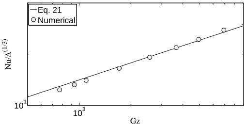
where Gz is the Graetz number. It is noticeable that dividing Eq. 21 by the factor 1/3 gives the correlation for Newtonian fluids.
Fig. 4 shows the concordance between numerical results and Nusselt correlation (Eq. 21).
103 101
Gz
N
u/
(1
/3
)
Eq. 21 Numerical
Fig. 4Nusselt number in smooth tube: correlation and numerical results
3. FLOW PATTERN DESCRIPTION 3.1 Motionless scraper
The description of the flow pattern is based on the analysis of the velocity field along the symmetry plane of the scraper. The velocity components in this region constitute a reliable footprint of the 3D flow structures existing in the heat exchanger tubes. The two-dimensional velocity field in the symmetry plane provides a reliable insight into the main flow structure, as well as the distribution of significant variables.
Fig. 5 and 6 show the non dimensional velocity field, u/U, for the motionless scraper (ω=0) and Reynolds number ReMR=17 and ReMR=80
respectively. These working regimes are sufficiently representative of the flow characteristics encountered in food industry equipment with severe fouling tendency. The ReMR=17 value represents the flow at low
Reynolds numbers, while the ReMR=80 value does for high Reynolds
values.
Following the sequence of the flow direction (left to right) in Fig. 5, a region of low velocity is found downstream the first plug, in the upper half of the tube. Afterwards, a high velocity region grows along the scraper pitch, which ends in another low velocity region upstream the next plug. However, in Fig. 6 there is also a low velocity region downstream the first plug followed by a high velocity region, but in this case it ends with the formation of a vortex when the stream impacts against the front side of the third plug.
The periodic configuration of the scraper forces the appearance of an odd-symmetry plane in the flow: the structures existing in the upper half of the tube, between the first and second plug, are repeated in the lower half of the tube, between the second and third plug.
A detailed representation of the vectorial velocity field in the impact vortex originated upstream the plugs is included in Fig. 6. The low velocity region downstream the plugs is also included, highlighting the opposed direction of the velocity vector to the mean flow. This structure indicates the existence of a separated region, associated to the flow recirculation downstream the plugs.
As a result of this analysis, a simple model of the flow mechanism for both, low and high Reynolds values, can be described as follows:
The main stream flows through the annular section until the next plug, turned 180º, is encountered. This plug blocks again the opposite tube section. At low Reynolds value the flow is deflected smoothly, leading to another low velocity region in front of the plug. Moreover, at high Reynolds values the stream impacts in the front side of the plug and forms a vortex. Then, the flow is deviated again, and a high velocity region appears.
The structures that appear in the next half-pitch are similar to those described above. However, they are located in the contrary side of the odd-symmetry plane, with opposite radial velocity components.
u/U: 0.14 0.41 0.68 0.95 1.22 1.49 1.76 2.03 2.30 2.57 2.84 3.11 Flow
Fig. 5 Velocity field in the symmetry plane of the tube, ReMR=17.
u/U: 0.20 0.60 1.00 1.40 1.80 2.20 2.60
Flow
Fig. 6 Velocity field in the symmetry plane of the tube, ReMR=80.
3.2 Dynamic scraper
The dynamic performance of the scraper comprises the two semi-cycles of the scraping process, with different flow patterns.
During the counter-current semi-cycle, the scraper moves in opposite direction to the mean flow, increasing the global blockage effect. The resulting velocity field for ReMR=17 and velocity ratio ω=1
is shown in Fig. 7 whereas Fig. 8 shows the velocity field for ReMR=80
and velocity ratio ω=0.5. The flow patterns encountered are similar to the corresponding motionless conditions. The movement of the scraper increases the local velocity field in the flow structures: the recirculation bubbles present a velocity level of the order of U, and the characteristic size of this region is augmented. Consequently, higher local velocities are found in the acceleration region situated in the opposite half of the tube. Moreover, for ReMR=80 the impact vortex presents also higher
local velocities.
If the velocity ratio ω increases, the effects noticed above are also higher, reaching to the ω=2 value (Fig. 9), where the flow pattern changes showing a different situation. The low velocity regions disappear and the acceleration region extends to almost the next plug. The bubble downstream de plug also extends until the acceleration region. The difference between high and low Reynolds is the presence of the impact vortex for the high ones. However, as the Fig. 9 shows, this vortex is near to disappear for ReMR=80, due to the expansion of
the acceleration region.
u/U: 0.20 0.59 0.98 1.37 1.77 2.16 2.55 2.95 3.34 3.73 4.12 4.52
Fig. 7Velocity field in the symmetry plane, ReMR=17, ω=1
counter-current
u/U: 0.20 0.60 1.00 1.40 1.80 2.20 2.60 3.00 3.40
Fig. 8Velocity field in the symmetry plane, ReMR=80, ω=0.5
counter-current
u/U: 0.29 0.86 1.44 2.01 2.59 3.17 3.74 4.32 4.89 5.47 6.04 6.62
Fig. 9Velocity field in the symmetry plane, ReMR=80, ω=2
counter-current
In the co-current semi-cycle, the scraper moves in the same direction of the mean flow. The velocity field for ReMR=80 and velocity
ratio ω=0.5 is depicted in Fig. 8. As the scraper moves slower than the mean flow, a blockage effect is still present. Nevertheless, the deviation of the flow does not generate the recirculation bubbles downstream the plugs, neither an impact vortex is found in the front face of the plugs. Maximum local velocities are consequently lower as well. The same effects occur for the low Reynolds values (except the existence of the impact vortex) until reach the velocity ratio value ω=1, where the scraper moves at the same velocity as the mean flow. This situation produces the same flow pattern for both low and high Reynolds values, and is depicted in Fig. 11. The movement of the scraper with ω=1 produces a uniform velocity field between two equivalent plugs without bubbles or acceleration regions.
u/U: 0.10 0.30 0.50 0.70 0.90 1.10 1.30 1.50 1.70 1.90 2.10
Fig. 10Velocity field in the symmetry plane, ReMR=80, ω=0.5
co-current
Once this value of velocity ratio is overcome, the flow pattern evolves in a different way for low and high Reynolds values. For ReMR=17 (Fig. 12) the flow is completely generated by the movement
of the scraper: the high velocity zones are in the front and back sides of the scraper and a recirculation bubble appears in the constriction. The effect of the flow produced by the pressure gradient have disappeared and. For ReMR=80 (Fig. 13) the flow is also governed by the scraper
noticeable in the flow pattern: high velocity regions are in the upstream side of the plug whereas the bubble located in the constriction does not coincide with the plug location like as in the ReMR=17 case, it is
displaced upstream.
u/U: 0.06 0.19 0.31 0.44 0.56 0.69 0.81 0.93 1.06 1.18 1.31 1.43
Fig. 11Velocity field in the symmetry plane, ReMR=80, ω=1 co-current
u/U: 0.10 0.31 0.52 0.72 0.93 1.14 1.35 1.55 1.76 1.97 2.17 2.38
Fig. 12Velocity field in the symmetry plane, ReMR=17, ω=2 co-current
u/U: 0.12 0.37 0.61 0.86 1.10 1.35 1.59 1.84 2.08 2.33 2.58 2.82
Fig. 13Velocity field in the symmetry plane, ReMR=80, ω=2 co-current
4. FRICTION FACTOR RESULTS 4.1 Motionless scraper
The analysis of friction factor characteristics is presented on the basis of the flow pattern assessment explained above. Fig. 14 shows the skin friction coefficient, Cf, in the tube wall for ReMR=80 in static conditions
(ω=0). As expected from the velocity fields depicted above, this distribution provides a fair description of the role of the flow structures on the pressure drop mechanisms.
Maximum values of the skin friction coefficient are found in the front side of the plugs, towards the opposite part of the tube where the bulk flow is deviated. The blockage imposed by the plugs forces the flow to separate and to increase its velocity, owing to the sudden contraction of the cross-sectional area.
The region of high shear stress extends towards the reduced cross-section region and further downstream. Progressively, the boundary layer grows along the tube wall side opposite to the plugs, yielding to a reduction of the local shear stress. A local wall shear stress increase is detected close to the front side of the next plug. This augmentation is caused by the vortex generated when the stream impacts on the plug, due to the relatively high local velocities that appear close to the tube wall.
Conversely, a huge region of low wall shear stress is found in the rear side of the plugs. This area is influenced by the low-velocity recirculation bubbles generated when the flow expands downstream the plugs. The further reattachment of the flow to the main stream yields to a progressive increase of the skin friction coefficient.
4.2 Dynamic scraper
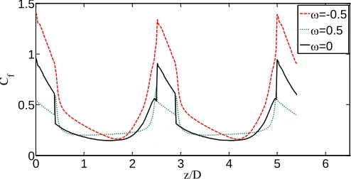
Circumferentially-averaged skin friction coefficient is depicted in Fig. 15. for ReMR=80 and ω=0, ω=-0.5 and ω=0.5.
Maximum values are found in the region occupied by the plugs. In this section, the skin friction coefficient augments during the counter-current semi-cycle, whereas lower values are found for the co-counter-current condition, compared to the motionless condition.
Nonetheless, the section between plugs (1.5 diameters downstream) presents a different trend. The skin friction coefficient downstream the plugs is higher in both co-current and counter-current semi-cycles than in static conditions. The low-velocity recirculation bubbles that appear
Level
u/U: 0.501 1.132 1.753 2.384 3.005
2 1 4
5 5
2
2
1
4 2
1
1
2
3 2 1 34
1 3
2 1 4
2
1 1
5
1
22
3
1 1
22
4
1
1
3 1
2 1
5
4 3
5
2 3
5
4
Cf: 0.05 0.25 0.45 0.65 0.85 1.05 1.25 1.45
P
·(D/2)
Cf: 0.05 0.25 0.45 0.65 0.85 1.05 1.25 1.45
Fig. 14Distribution of skin friction coefficient in the tube wall. Cross sectional velocity distribution is shown in 9 discrete positions
0 1 2 3 4 5 6
0 0.5 1 1.5
z/D C f
=-0.5
=0.5
=0
Fig. 15 1D skin friction coefficient distribution along the pitch
in the motionless performance contribute to a low shear stress downstream the plugs. However, in co-current conditions this recirculation bubbles are not observed. In counter-current conditions, the recirculation bubbles contribute to an increased wall shear stress due to the higher local velocities of the separated flow.
Close to the front side of the plugs, the lowest skin friction coefficient is found in co-current conditions, as the parallel movement of the scraper avoids the formation of the impact vortex, and the deviation of the flow is less affected by the blockage. The highest values of skin friction coefficient in that region are found for the counter-current semi-cycle, owing to the intense impact vortex and high local flow velocities to overtake the moving plug.
Fig. 16 shows the results of Fanning friction factor for a wide range of velocity ratios (-2<ω<-0.1) and Reynolds numbers in the range 15<ReMR<200, in counter-current mode. The results are contrasted with
the solution of the motionless scraper (ω=0). For a constant Reynolds number, Fanning friction factor increases in all working conditions for
increasing velocity ratio, with respect to the static situation. This is due to the blockage effect imposed by the scraper when it moves in opposite direction of the mean flow. For Reynolds number ReMR≈20, pressure
drop augmentations of 6% with respect to the motionless scraper are found for ω=-0.1, and 180% for ω=-2. For Reynolds number ReMR≈200, these values are respectively of the order of 18% and 660%.
This fact indicates the poorer performance of the insert device for increasing Reynolds
101 102
0.1 1 10
Re MR f
h
counter-current
=0
=-0.1
=-0.5
=-1
=-2
Fig. 16 Fanning friction factor in counter-current semi-cycle
number. For ReMR≈20 and ω=-0.1, it can be stated that, fh ReMR0.9
while for ReMR≈200, this influence is evaluated asfh ReMR0.25, which
is a relation typically found in turbulent pipe flows. Similar trends are observed for higher velocity ratios. This result reveals the quality of the insert device as a turbulent promoter at low Reynolds number, working in counter-current mode.
Fig. 17 shows the results of Fanning friction factor in co-current mode, for velocity ratios 0.1<ω<2 and Reynolds numbers in the range 15<ReMR<200. The general trend is the successive decrease of Fanning
friction factor for increasing velocity ratio, for a given value of Reynolds number. This result agrees with the conclusions of the flow pattern assessment, indicating a lower blockage effect when the scraper moves in the same direction of the mean flow.
For ω≤1, the influence of Reynolds number on friction factor remains Re0.9
MR h
f . This characteristic is typical of laminar flows, and allows stating that the scraper in co-current mode does not work as a turbulent promoter.
For ω=2, friction factor is not monotonic. This behaviour is associated to a different flow mechanism, as the scraper moves faster than the fluid. The study of this condition is beyond the scope of this paper.
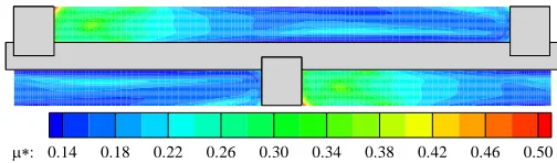
5. APARENT VISCOSITY DISTRIBUTION Fig. 18 shows the numerical results of the dimensionless apparent viscosity distribution (Eq. 22) in the symmetry plane for ReMR≈120
with =0.
1 *
ana
L
u
K
(22)These results correspond to the hydrodynamic problem, solved without considering the energy equation, therefore apparent viscosity changes only with respect to the shear rate. Strong velocity gradients appear along the SSHE due to the presence of the plugs, leading also to important apparent viscosity variations. Fig. 18 shows the velocity gradient field (s-1) in the symmetry plane. The relation between the apparent viscosity and the velocity field (Fig. 6) can be observed.
101 102
0.1 1 10
Re MR f
h
co-current
=0
=0.1
=0.5
=1
=2
Fig. 17 Fanning friction factor in co-current semi-cycle
The uniform low velocity zone in the rear side of the plug, where there are not velocity gradients, generates a high apparent viscosity zone. The high velocity zone on the constrain produced by the plug blockage, where there is an important flow acceleration (especially near the walls), generates a region of low apparent viscosity. In this zone, coinciding with the maximum axial velocity position, viscosity rises owing to a minimum in the velocity gradient.
The apparent viscosity distribution also changes with the scraper movement, with a similar trend to the velocity field distribution. This effect can be appreciated in Fig. 20, which shows the variation of the apparent viscosity, symmetry plane-averaged along the pitch, for ReMR≈80 with ω=-0.5, ω=0 and ω=0.5. It is noticeable that the scraper
movement (in both directions) avoids the low velocity zone approximately one diameter downstream of the plug, yielding to a significant viscosity decrease in this region. In the other hand, two diameters and a half downstream, the deceleration of the flow in the plug constriction for ω=0.5 rises the viscosity compared with ω=0, while for ω=-0.5 the viscosity decreases, due to flow acceleration.
0.14 0.18 0.22 0.26 0.30 0.34 0.38 0.42 0.46 0.50
Fig. 18Apparent viscosity field in symmetry plane for ReMR≈80 (ω=0)
As expressed in Eq. 8, apparent viscosity, shear stress and velocity gradient are related. Therefore, changes in one of these magnitudes will affect the others. This fact can be observed in Fig. 21, which shows the variation of the apparent viscosity, symmetry plane-averaged, for ReMR≈80 with ω=-0.5, and the circumferentially-averaged skin friction
coefficient, where the velocity gradient is also high (mainly in the constriction), viscosity decreases until a minimum, whereas in the zones with a low skin friction coefficient, due to a low velocity gradient (e.g. downstream the plug) the viscosity reaches a maximum
200 600 1000 1400 1800 2200 2600 3000 3400 3800 4200 4600
Fig. 19Shear rate field (s-1) in symmetry plane for ReMR≈80 (ω=0)
0 1 2 3 4 5 6
0.4 0.6 0.8 1 z/D a * =-0.5 =0.5 =0
Fig. 20Apparent viscosity distribution along the pitch for ReMR≈80
(ω=-0.5, ω=0 and ω=0.5)
0 1 2 3 4 5
0.2 0.6 1 1.4 z/D C f
0 1 2 3 4 5 6
0.50 0.55 0.60 a* a* C f
Fig. 21Apparent viscosity distribution and 1D skin friction coefficient distribution along the pitch for ReMR≈80 and ω=0.5
6. HEAT TRANSFER RESULTS 6.2 Temperature effect in flow variables
Heat transfer simulations under uniform wall heat flux are performed for the motionless scraper in a wide range of laminar Reynolds numbers. According to Eq. 10 and Eq. 11, the resulting temperature distribution modifies the viscosity field. Due to this effect, flow variables change with respect to the hydrodynamic problem. Figure 22 shows the velocity and viscosity profiles in the symmetry plane at 3P/4 downstream the plug. Viscosity decreases especially near the wall, where the fluid temperature is higher. The velocity profile does not show an important variation, and the temperature effect in the Fanning friction factor only represents a decrease of 0.003%.
These results justify the isothermal approach of the study of the flow pattern and Fanning friction number.
6.3 Viscous dissipation effect
Fig. 23 shows the temperature distribution due to the viscous dissipation (q”= 0) in successive cross sections. Maximum temperature increases of 0.02K are reported.
These results highlight that the influence of the viscous dissipation for this CMC concentration is negligible, but the temperature distribution shows the location of zones with important shear rates. Due to the oscillating path of the mean flow (showed by the stream traces), a zone with higher temperature appears near the wall, and follows the main flow stream. Likewise, the central zone of the main flow presents a lower temperature, owing to the abrupt decrease of shear stress. The mixing effect of the vortex in the section upstream the plug is also visible, where the warm layer near the wall is removed.
Viscosity 3P/4 3P/4 + Velocity Hydrodynamic problem Thermal problem o Viscosity 3P/4 3P/4 + Velocity Hydrodynamic problem Thermal problem o +++++ ++ + + ++ + + + + + + + + + + + + + + + +++ ++++ ++ + + +++ + + ++ ++++++++++++++ r/R 1 0 1 + + + + ++++++++++++++ + + + + + + + + + + + r/R u /U 1 0 3 ++++ + + ++++++ + + + + + + + + + + + + + + + + +
Fig. 22 Viscosity and velocity variations due to the temperature effect on power-law model, for ReMR≈80 (ω=0)
X Y
Z
0.000 0.003 0.006 0.009 0.011 0.014 0.017 T(K):
Flow
Fig. 23Temperature contours with viscous dissipation in successive cross sections and stream traces, for ReMR≈80 (ω=0)
6.3 Temperature field and Nusselt number results
Fig. 24 shows the temperature distribution in the symmetry plane for ReMR≈80. It reveals a zone of high mixing, just in front of the plug,
where the temperature near the wall decreases to the mean flow temperature due to the vortex presence: warmer fluid near the wall is removed and replaced by cool fluid from inside of the duct. Moreover, behind the plug, the absence of flow generates a local high temperature field. This region is gradually reduced up to the next constriction, where the high velocity reduces the layer thickness to a minimum value.
The global Nusselt number was calculated by means of,
f w h g h T T q k D Nu " , (28)
Nusselt number for smooth tube with fully developed laminar flow is also depicted. The flow pattern changes that take place beyond ReMR≈80, mainly the vortex generation, lead to a new trend of Nusselt
number augmentation. This behaviour is also reported in the Fanning friction factor results (Fig. 16), and can be related to a low-Reynolds number turbulence promotion.
T(K): 300.5 301.5 302.5 303.5 304.5 305.5 306.5 307.5 308.5
Fig. 24Temperature distribution in symmetry plane with q”=5000W/m2
(up), and detail of the plug zone (down) for ReMR≈80 (ω=0)
101 102
101 102
ReMR
Nu
h
g
Numerical results Smooth tube
Nu4.36(1/3)
Fig. 25 Global Nusselt number (ω=0)
This effect can be appreciated in Fig. 26, which shows the Nusselt number distribution across the tube wall. Higher Nusselt numbers are present in zones with elevated shear rate (see Fig. 23) but mainly upstream the plugs, where the vortex replaces the warm fluid near the wall by cool fluid. The zone behind the plug presents a low Nusselt number due to the low-velocity recirculation bubbles.
Vortex mixing effect is also noticeable inFig. 27, which shows the Nusselt number distribution along the pitch for ReMR≈17 (without
vortex) and ReMR≈170 (with vortex). The Nusselt number augmentation
for ReMR≈170 is of the order of 9 times respect to ReMR≈17 in this zone,
two diameters and a half downstream. Behind the plug, three diameters downstream, Nusselt number decreases rapidly until the ReMR≈17 level.
Nu: 0 82 163 245 327 408 490 571 653 735 816 898 980
P
·(D/2)
Fig. 26Distribution of Nusselt number in the tube wall for ReMR≈80 (ω=0)
0 1 2 3 4 5 6
0 100 200 300
z/D
Nu
h
ReMR=17
ReMR=170
Fig. 27Nusselt number distribution along the pitch, for ReMR≈17 and
ReMR≈170 (ω=0)
7. CONCLUSIONS
1. A 3D model of an innovative SSHE is developed to study the thermal-hydraulic characteristics, with a non Newtonian fluid. The range covered was ReMR≈14-170 and Pr≈980-1360. Power law
model with temperature dependent properties was implemented in FLUENT, for a CMC medium viscosity 2% solution in water. 2. Reliability of the model was checked by comparing numerical
solutions in annular and smooth ducts with the available analytical expressions and correlations, showing an excellent agreement. 3. A simple model of the flow pattern is reported. Mean flow
presents an oscillatory path, and local flow structures are identified: recirculation bubbles, impact vortex and acceleration region.
4. Wall shear stress and fanning friction factor are investigated and related with the flow characteristics. Influence of Reynolds number and velocity ratio ω is studied for a wide range of working conditions (motionless scraper, counter-current mode, co-current mode).
5. Viscosity variations of 72% were encountered between different zones along the SSHE due to the existence of high shear rates. The scraper movement also generated viscosity maximum variations of 27% in a same zone, mainly near the plugs.
6. Uniform wall heat flux condition was simulated for the motionless scraper. Due to the vortex generation, a mixing effect in front of the plug was observed for ReMR≥80, with Nusselt number
augmentations of 100% in this zone. Also a low heat transfer zone appears behind the scraper. Viscous dissipation does not have an important influence with this CMC concentration.
ACKNOWLEDGEMENTS
This research has been partially financed by the DPI2007-66551-C02-01 grant of the Spanish Ministry of Science and the company ―HRS Spiratube‖. The authors are grateful to the Computer Centre of SAIT (UPCT) for providing the technical resources for CFD computations.
NOMENCLATURE
D Tube inner diameter (m) d Wire diameter (m) a Geometrical constant (-) b Geometrical constant (-) Dh D-d, hydraulic diameter (m)
f Fanning friction factor (-)
m Mass flow rate (kg/s) n Flow behaviour index (-) p Wire pitch (mm) P Pressure drop (N/m2) q” Heat flux (W/m2)
R Interfacial thermal resistance (m2K/W) T Temperature (ºC)
T Temperature difference (ºC) u Velocity (m/s)
U Mean flow velocity (m/s)
Special characters
(3n+1)/4n (-) Shear rate (s-1) Density (kg/m3)
W Wall shear stress (N/m
2
) ω velocity ratio, (us/U) (-)
a Apparent viscosity (kg m
-1
s-1)
a
* Dimensionless apparent viscosity (-) (Eq. 22)
Dimensionless groups
Cf Skin friction coefficient (2w)/(U2)
Gz Graetz number (mcp)/(kLx)
Nu Nusselt number (Dq”)/(kT) Nux Local Nusselt number
ReMR Reynolds number (Eq. 13)
Subscripts
MR Metzner and Reed x Local conditions b Bulk conditions w Wall conditions
s Scraper
h Based on hydraulic diameter
g Global
0 Reference conditions
REFERENCES
Bergles, A.E., 2002, "ExHFT for fourth generation heat transfer technology", Experimental Thermal and Fluid Science, 26(2-4), 335-344.
http://dx.doi.org/10.1016/S0894-1777(02)00145-0
Bird, R.B., Stewart, W. E., and Lightfoot, E. N., 1960, Transport Phenomena, Wiley, New York.
Chabbra, R. P., and Richardson, J. F., 2008, Non-Newtonian Flow and Applied Rheology - Engineering Applications, 2nd ed., Butterworth Heinemann – Elsevier.
De Goede, R. and De Jong, E.J., 1993, "Heat transfer properties of a scraped-surface heat exchanger in the turbulent flow regime", Chemical Engineering Science, 48(8), 1393-1404.
http://dx.doi.org/10.1016/0009-2509(93)80046-S
FLUENT user guide, Fluent Inc.
Freitas, C.J., 2002, "The issue of numerical uncertainty", Applied Mathematical Modelling, 2 (2), 237-248.
http://dx.doi.org/10.1016/S0307-904X(01)00058-0
Ghannam, M.T. and Esmail, M.N., 1996, "Rheological properties of Carboxymethil cellulose", Journal of Applied Polymer Science, 64(2), 289-301.
Joshi, S. D. and Bergles, A. E., 1980, "Experimental Study of laminar Heat Transfer to In-Tube Flow of Non-Newtonian Fluids", Journal of Heat Transfer, 102, 397-401.
Kozicki, W., Chou, C.H., and Tiu, C. 1966, "Non-Newtonian Flow in ducts of arbitrary cross-sectional shape", Chemical Engineering Science, 21(8), 665-679.
http://dx.doi.org/10.1016/0009-2509(66)80016-7
Machac, I., Dolecek, P., and Machacova, L., 1999, "Poiseuille flow of purely viscous non-Newtonian fluids through ducts of non-circular cross section", Chemical Engineering and Processing, 38(2), 143-148.
http://dx.doi.org/10.1016/S0255-2701(98)00076-2
Martínez, D.S., García, A., Solano, J.P., and Viedma, A., 2010, ―Heat transfer enhancement in smooth tube with wire coil insert in laminar and transitional Non-Newtonian flow‖, HEFAT2010-1330. Proceedings of 2010 7th International Conference on Heat Transfer, Fluid Mechanics and Thermodynamics,Turkey.
Matsunaga, T., Roh, M., and Kamota, T., 2003, "Heat transfer and power consumption in a scraped surface heat exchanger", International Institute of Refrigeration, Washington D.C., USA.
Metzner, A. B. and Reed, J. C., 1955, "Flow of non-Newtonian fluids— correlation of the laminar, transition and turbulent flow regions", AIcHEJ. 1, 434-440.
Müller-Steinhagen, H., 2000, Handbook of Heat Exchanger Fouling – Mitigation and Cleaning Technologies, Publico Publications.
Solano, J.P., 2009, PhD Thesis, Análisis del flujo y de la transmisión de calor en intercambiadores de superficie rascada por movimiento lineal alternativo, Universidad Politécnica de Cartagena (Spain).
Steinhagen, R., Müller-Steinhagen, H., and Maani, K., 1992, "Problems and costs due to heat exchanger fouling in New Zealand industries", Heat Transfer Engineering, 14, 19-30.
Trommelen, A.M. and Beek, W.J., 1971, "Flow phenomena in a scraped surface heat exchanger", Chemical Engineering Science,
26(11), 1933-1941.
http://dx.doi.org/10.1016/0009-2509(71)86035-9
Versteeg, H. K. and Malalasekera, W., 1995, An introduction to computational fluid dynamics, The finite volume method, Ed. Longman Group Ltd.