Int. J. Adv. Res. Sci. Technol. Volume 4, Issue 1, 2015, pp.248-252
International Journal of Advanced Research in
Science and Technology
journal homepage: www.ijarst.com
ISSN 2319 – 1783 (Print)
ISSN 2320 – 1126 (Online)
Dynamic channel gain parameter based resource allocation strategy for cellular system
Santhoshi M* and Ch. Rajasekhar
Department of ECE, AITAM, Tekkali, Andhra Pradesh, India.
*Corresponding Author’s Email: [email protected]
A R T I C L E I N F O A B S T R A C T
Article history: Received Accepted Available online
20 Nov. 2014 11 Dec. 2014 20 Jan. 2015
Future mobile communication systems will be designed to support a wide range of data rates with complex quality of service matrix. The demand of higher bandwidth and data rates has been increased substantially during recent years. In order to achieve efficient resource utilization in all sorts of deployment scenarios and QoS requirements. Several interference reduction techniques have been suggested in past and proved to be effective in reducing the interference to some extent and thereby increase system capacity. Till now the research was done only on to control intracellular interference but in this paper it is discussed about the intracellular interference. However, in a highly loaded system, the problem of intercellular interference remains an important issue. In this paper, the intercellular interference problem of scheduling process is to be overcome by introducing a new and efficient resource allocation strategy called weight Matrix (WM) and with dynamic channel gain parameter. The proposed algorithm is to evaluate the existing resource allocation for performance evaluation. In this paper we increase system throughput and decrease the packet loss and we analyze the communication period. Finally we show how the throughput is increased compared to fixed algorithm. Also we show how the packet loss is decreased compared to fixed algorithm. This work considered single carrier but it can further be extended with multicarrier systems and also it can be extended to priority queuing and also we can give power ratings to users.
© 2015 International Journal of Advanced Research in Science and Technology (IJARST). All rights reserved. Keywords:
Weight Matrix (WM),
Rise over Therml noise (RoT), High Speed Downlink Packet Access (HSDPA).
Introduction:
In order to achieve efficient resource utilization in all sorts of deployment scenarios and QoS requirements in the future wireless cellular systems (3G), new resource allocation methods must be developed. Importance of resource scheduling was appreciated with the support of high data rate services in the evolution of UMTS standard to High Speed Downlink Packet Access (HSDPA) and Enhanced Uplink. A variety of resource allocation strategies and schemes, mainly for downlink, can be found in references [1]. Uplink resource allocation methods can be categorized as centralized or decentralized in terms of the network location/ node in which scheduling takes place. In an interference-limited system such as UMTS, the uplink cell capacity is basically limited by the total received uplink power at the base station due to the transmit power limitation of user terminals. In decentralized scheduling, each base station assigns radio resources to its users on a priority basis until the estimated Rise over
Thermal noise (RoT) level reaches a pre-defined target. Recent studies in Enhanced Uplink UTRA, also called High Speed Uplink Packet Access (HSUPA), show that the decentralized scheduling has better performance compared with centralized one [2].
Int. J. Adv. Res. Sci. Technol. Volume 4, Issue 1, 2015, pp.248-252 Evolution of mobile systems to 3G:
Realizing and implementing 3G can be achieved effectively through a series of incremental steps, building on the global track record of GSM - the world's most successful digital cellular technology. With the evolution from GSM through GPRS and EDGE to WCDMA, a new mobile Environment is being created. By growing capacity and capabilities seamlessly from 2G to 3G, new services are being introduced and experienced that will emphasize lifestyle rather than technology. The following fig shows the evalution of Mobile systems to 3G
Fig. 1: Evolution of mobile systems to 3G
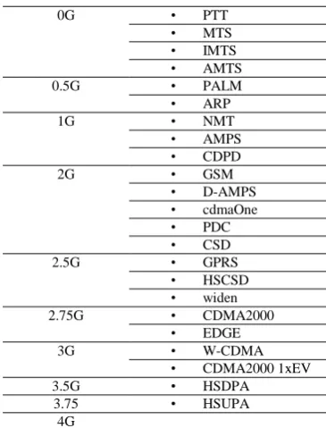
Table: 1. Mobile Phone and data standards
0G • PTT
• MTS
• IMTS
• AMTS
0.5G • PALM
• ARP
1G • NMT
• AMPS
• CDPD
2G • GSM
• D-AMPS
• cdmaOne
• PDC
• CSD
2.5G • GPRS
• HSCSD
• widen
2.75G • CDMA2000
1xRTT
• EDGE
3G • W-CDMA
• CDMA2000 1xEV
3.5G • HSDPA
3.75 • HSUPA
4G
Intercellular interference control:
Uplink cell capacity in interference-limited systems is basically limited by the total received power at the base station. As the uplink load increases, user terminals have to increase their transmit power substantially to overcome the increased interference level at the base station. Due to the fact that the transmit power of user terminals is limited, total received power at the base station actually limits the uplink capacity. In
decentralized scheduling, each base station assigns radio resources (i.e. rate and time) to its users until the estimated RoT reaches a predefined target value,
RoTtarget. We assume RoTtarget is a fixed target value set
by the network controller to maintain the uplink interference level [2].
The main shortcoming for decentralized scheduling in general becomes more visible in a multi-cell scenario where a considerable proportion of RoT is inter cell interference and base station has little knowledge about and control upon. By inter cell interference here, we mean inter cell multiple-access interference in general i.e. any signal received by a base station coming from those users which belong to other cells. The relation between cell RoT and inter cell interference is given in (1). The RoT of cell j (RoTj) is defined as the total in-band received power at base station j (BSj ) over thermal noise. Let be the received noise power in BSj , bsj be the set of BSj users, Pi be the transmission power of user i and Gi,j be the channel gain from user i to BSj. For M active users in the network, can then be written as:
∑ ∑ (1)
For simplicity, we have not considered soft hand over in this paper meaning the user is connected only to one base station at a time. To highlight the importance of inter cell interference problem and show the impact of it in the overall interference outage performance and resource utilization, we set up a specific simulation scenario. In this scenario, all the cells have same traffic distribution and interference condition (i.e. identical user distribution per cell). In each cell 10 users with full buffer are waiting for transmission. Same user distribution makes the scheduling order and therefore generated interference exactly the same in all cells. We have chosen this extreme scenario to highlight the effect of intercell interference in its extreme situation as the worst case scenario. We also use wrap-around technique, which makes all the cells identical. Users are randomly and uniformly distributed over one cell and then repeated with identical pattern over other cells. Other simulation parameters are same as in table II. We use the decentralized scheduling algorithm in [6] which allocates resources individually in each cell. Assumption of full buffer occupancy for users helps to model and study the network behavior under heavy traffic load.
Resource allocation strategy:
The aim of resource allocation in wireless cellular system is to assign radio resources to individual users in a way to achieve maximum system capacity whilst meeting the required quality of service. In this section, we consider a basic scenario where resource allocation is down to assigning transmission rate and time to individual users with the objective of throughput maximization. To analyze the problem, we begin with the single cell scenario and then extend the conclusion
GSM
GPRS
UMTS
EDGE
2G
VOICE 9.6 kbps
2.5G
115kbps Packet
2.75G
3 G
Int. J. Adv. Res. Sci. Technol. Volume 4, Issue 1, 2015, pp.248-252 to the multi-cell case. Without loss of generality, earlier
transmission rates are chosen from a limited set of rates. Let Si,1 denote Candidate Rate Set (CRS) of user i, which includes all the allowed transmission rates for the user to choose from. Rate ”0” is always included in Si,1, and will be chosen if the user is not scheduled to transmit in the current scheduling instant. We treat transmission rates in different CRSs as different items even if they have the same
Let S1 denote the union of all the CRSs from S1,1 to SM1,1, and M1 is the total number of users in the cell sharing the radio resource pool. Choosing an element t from set S1 is an assignment action, which means allocating a specific transmission rate to a particular user. Apparently, each assignment action generates a certain amount of throughput while consumes some amount of the cell capacity. We use binary variable xt to indicate whether element t is chosen or not (1 for ’Yes’ and 0 for ’No’). pt and ct,1 denote the generated throughput and consumed cell capacity respectively if element t is chosen. pt is equal to the transmission rate itself, whereas ct,1 can be interpreted differently, e.g. as consumed BS transmit power or generated load factor , depending on the system type. Using above terms and definitions, the Single Cell Radio Allocation Problem (SCRAP) can be described as follows: given a particular system snapshot (cell capacity, user location, propagation and traffic status etc.), how to choose elements from set S1 in each scheduling instant so as to achieve maximum system throughput, subject to the following two constraints: C1 : The aggregated cell capacity consumption of all the chosen elements from S1 should be less than the total available cell capacity Cap1. C2 : for each CRS (S1,1 , , SM1,1), only one element is chosen. Mathematically, SCRAP can be formulated as follows:
∑
∑
∑ ∑
Weight matrix concept:
One of the main challenges in resource allocation in multicell system is the control of intercell interference. In uplink scheduling, the basic problem is to assign appropriate transmission rate and time to all active users in such a way that result in maximum radio resource utilization across the network whilst satisfying the QoS requirements of all the users. Amongst other constraints, another important factor in the resource allocation is the users transmit power. For network of M users and N cells the constraints to be satisfied are Cnst1: For each active user i in the network, its transmit power Pi must be maintained in an acceptable region defined as
Pi, max is the maximum transmission power available to the user due to hardware limitation and/or any other restrictions. Cnst2: The total received power at base station should be kept below a certain threshold for all N base stations in the network (as a load control measure in a single-carrier Spread Spectrum system). We use Rise over Thermal noise (RoT) as defined in HSUPA [2] to represent the interference constraints. RoTj is the total in-band received power at the base station j BSj) over thermal noise. Let N’ be the receiver noise power in a BS, Pi be the transmission power of user i and Gi,j be the channel gain from user i to BS j. For M active users in the network, RoTj can be written as
∑ (2)
In this case Cnst2 can be formulated as
Where RoTtarget is assumed to be a fixed target value set by the network operator to maintain the uplink interference level. Cnst3: For each user, depending on its channel type (e.g. pedestrian, vehicular) and speed, each rate k has a minimum required SINR called SINR target. SINR target is the signal to noise plus interference ratio required at the serving base station j if rate k is being assigned to the user in order to achieve a given block/frame error rate. Rate k . {1, · · ·,K} is the highest rate acceptable (and therefore is the preferred rate) for user i with serving base station j if SINR target is the highest that can be achieved under both Cnst1 and Cnst2
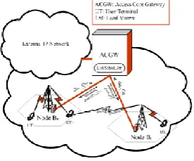
Weigth Matrix (WM) can be regarded as a database containing the load factors of all active users in the network. WM scheduling can be implemented in both centralized and decentralized strategies. In a decentralized WM scheduling, each base station should implement identical WM database. Here for simplicity, we only present the centralized WM scheduling where a central scheduler entity assigns radio resources to all the users in the network. Figure 4.1 illustrates an example of WM scheduling implementation based on the proposed system architecture for
Int. J. Adv. Res. Sci. Technol. Volume 4, Issue 1, 2015, pp.248-252 The 3rd Generation Long-Term Evolution (3G
LTE) [7]. We assume the averaged channel gain (over the scheduling period) from users to base stations is known to scheduler prior to rate assignment. In a network of M users and N cells, WMi, j is the load factor contributed by user i at BS j
∑ (3)
From the WMi, j values stored in column j of WM database, RoT of cell j can be written as
∑
(4)
Note that RoTj obtained from (2) is identical to RoTj definition given in (4). Let BS j be the serving base station for user i which controls user’s transmission power and Gi, be the total channel gain from user i to BS j averaged over scheduling period. SINRi, j can be
written as,
(5)
Let pi,k be the required transmit power for user i should it be assigned the rate . Starting with the highest applicable rate from the set (i.e. k = K), for rate k to be assigned to user i, Cnst 3 must be satisfied. Therefore the minimum required SINRi, j is SINR target, k . Also recall the aim of WM rate assignment to keep RoTj always as close as possible (ideally equal) to RoT target. By rearrangement of (5), replacing SINRi,j with SINR target, k, Pi with pi, k , and RoTj with RoT target, required transmit power for user i (should it be assigned rate k) can be found as
(6)
However, rate k and consequently pi,k is acceptable if and only if all three constraints are satisfied. First of all, pi,k obtained from (6) must satisfy Cnst1 which states the maximum user’s transmit power. Cnst3 constraint is already satisfied by considering SINRtarget,k. as SINRi, j. Additionally, pi,k must satisfy the Cnst2 which takes into account the impact of assigning rate k to user i on the intercell interference. This ensures the intercell interference caused by user i in other cell does not increase other cells’ RoT above RoTtarget. In order to check this, next step is to update WMi,n for all the elements in row i of Load Matrix. WMi,n is the load factor imposed by user i in cell n using rate k defined as
∑
(7) From (2) one can estimate the new RoT for all other cells and check if the Cnst2 constraint has been satisfied. If so the rate k is the highest acceptable rate for user i and will be assigned, otherwise the same process is repeated for the rate k-1 and so on. If at the end, none of the rates k . {1, · · ·,K} can satisfy the three constraints, user i will not be scheduled for transmission at this scheduling instant and will be given higher priority for the following scheduling instant.
After the first round of rate assignment to all users, WM elements are updated and new RoT is calculated for each cell using (4). This is necessary because (6) and (7) are valid only if RoT is close to the RoT target. Since the rate assignment is an NP-complete problem (see section III), it is not possible to exactly achieve RoT target in all cells in the first round of rate assignment.
However, there is a tradeoff between maximum cell throughput and fairness amongst users [5]. Priority functions are used to rank users in the scheduling process and make a balance between cell throughput and fairness. Commonly used priority functions are Round Robin, DL SINR (also called Max C/I), Proportional Fair and also most recently introduced Score-Based [9]. The Round Robin tries to maximize fairness amongst users regardless of a user channel condition and therefore results in poor throughput performance. Max C/I on the other hand, ranks users in terms of their channel quality and aiming for maximizing cell throughput at the expense of fairness. Both Proportional Fair and Score-based functions performance are better than Round Robin in terms of throughput and better than Max C/I in terms of fairness. Load Matrix concept, provides a generic solution for resource scheduling that does not preclude any priority function and can be combined with any of them. However, priority function has major impact on overall system performance for any scheduling algorithm including the WM. Here a priority function is introduced based on a user’s load vector that includes intra and intercell impact on the network. It is evident that giving priority to a user with better channel condition increases the cell throughput but in a multicell network could have severe impact on the throughput of other cell’s. Here it is considered by defining Global Proportional Priority function as
∑ (8)
where Gi,j is the total channel gain from user i to BS j averaged over the scheduling period. The WM approach tries to maximize network capacity through inter and intracell interference management. Table I summarises WM algorithm used for rate assignment in a multicell wireless system. The first step is initialization where all the WM elements are set to zero and also users in each cell are sorted according to the priority function in (7). The WM allocation process simultaneously increases allocated resources in each cell to avoid interference imbalance amongst the cells. The process consists of a number of assignment rounds equal to the maximum number of users per cell .
Int. J. Adv. Res. Sci. Technol. Volume 4, Issue 1, 2015, pp.248-252 will not cause interference outage. If CC fails,
scheduler attempts the next available rate and continues until CC is satisfied. Then the user is considered scheduled and will be removed from the user priority list of its serving cell. The scheduling process continues until all the users are processed. In the WM scheduling process, the CC function is especially important and plays a major role in the overall system performance. In particular, a margin concept rather than a fixed threshold for RoTtarget is introduced.
Simulation Results:
Fig. 3: System Throughput plot when 1,2 ,3 ,4 ,5 ,6 cells communicating in each instant respectively with each other.
Fig. 4: System Throughput plot when 5,4,3,4,5,3 cells communicating in each instant respectively with each other
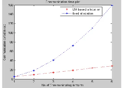
Fig. 5: Communication delay when1,2 ,3 ,4 ,5 ,6 cells communicating in each instant respectively with each other.
Fig. 6: packet lost plot when 5,4,3,4,5,3 cells communicating in each instant respectively with each other
Conclusion:
For the implemented design the simulations were performed for different case study. The result for different offered load(weight) at different channel characteristic was observed. The quality metrics such as throughput, communication delay, and packet loss are evaluated. The obtained observation illustrated that the developed methodology for resource allocation based on channel gain parameter can improve the performance of the suggested system as compared to the existing method. The performances were observed to be improved and the evaluation is carried out for different level of system load. The observation illustrates that as the number of users added where the conventional method takes larger time for computation and processing, due to network overhead. The proposed method improves the performances for different offered load.
About Authors:
Santhoshi M is a P.G student of Department of ECE, AITAM, Tekkali, Andhra Pradesh, India. And Ch. Rajasekhar is presently working as Associate Professor in the Department of ECE, AITAM, Tekkali, Andhra Pradesh, India.
References:
1.G. S. Rao, Mobile and cellular commnunications Pearson 2010.
2.GPP TR 25.896, Feasibility Study of Enhanced Upli nk for UTRAFDD V6.0.0, www.3gpp.org, Mar. 2004. 3.I. B. Kim and M. L. Honig, “Resource allocation for
multile classes of DS- CDMA traffic,” IEEE Trans. Veh. Technol., vol. 45, no. 6, pp.506-519, May 2000. 4.An Efficient Resource Allocation Strategy for Future