The Developed Security System Based on
Communication Technology with Internet
Networks
Pairach Tanuphol and Prayong Likitkarnpaiboon
Faculty of Engineering, Saint John's University, Bangkok, ThailandAtthapol Ngaopitakkul
Faculty of Engineering, King Mongkut's Institute of Technology Ladkrabang, Bangkok, Thailand Email: [email protected]
Abstract—The security automation system technology is unique from other systems which give ability to the user to control the system from any location around the world through internet connections. For this reason, the internet networks play a vital role in the field of security Systems. This paper presents a security system based on communication technology. The security system uses smoke sensors, motion sensors, and magnetic sensors to detect environment conditions, using a microcontroller to control system operation. The output from the devices is used as raw data and then sent to analyze with a central computer using The Delphi software. The program will send signal to operate the alarm system and it can operate on the designed webpage. By considering experimental results, all of sensor devices and notification system can work realizable and effectively.
Index Terms—security system, communication technology, sensors
I. INTRODUCTION
Nowadays, communication technology has been widely developed. Thus, there is new technology emerged to easily communicate, i.e. Wi-Fi, 3G, 4G, and so on. People around the world can easily interact with each other because there are communication networks installed in all areas: enterprises, department store, public places, and homes. Generally, the communication networks are allowed to access all times in term of convenience and easy usage. In addition, the communication networks can be used to send data as control signal.
Bahtiyar et al. [1] present a framework to assess trust to security systems of web services. The framework is used to improve an automated system to assess trust of a specific security system protecting web services. Zhaozheng et al. [2] investigate a set of Internet service security system. RFID technology, GSM communication technology, and LCD display are studied by Pinggui et al. [3]. The results indicate that the proposed security can effectively prevent campus safety accidents. Paper [4]
Manuscript received March 16, 2018; revised June 20, 2018.
proposes the design of an Automated Office receptionist system using Raspberry Pi 3 and an Android Application. The proposed system can eliminate manual assistance and also improve the security with simple devices and low costs. Tanwar et al. [5] present a security alert system based on advanced Internet of Thing to detect an intruder or any unusual event at home. A small Pyroelectric Infrared (PIR) module and raspberry pi are used to reduce the delay during process. Thus, the proposed technique is low cost for a home security system and flexible usage. Kaliyamurthy et al. [6] investigate combination of user and system interaction, whole together in the course of providing efficient secured network using multilevel system and user intervention which in turn reduces the system or the user's possibility of false perception in securing the network. The physical network environment threat data is analyzed as a Decision Support System.
Communicative technology is applied to the easily accessible safety systems of life and property. Thus, communicative technology which is an internet network is developed to use as monitor and notification systems using a microcontroller to control and detect. Additionally, when the communicative technology is cooperated with a designed software program, it can be alerted through the user's computer. This paper presents a security system uses smoke sensors, motion sensors, and magnetic sensors to detect environment conditions, using a microcontroller to control system operation. The output from the devices is used as raw data and then sent to process with a created program. The program will send signal to operate the alarm system and it can operate on the designed webpage.
II. EXPERIMENTAL TEST SET DESIGN
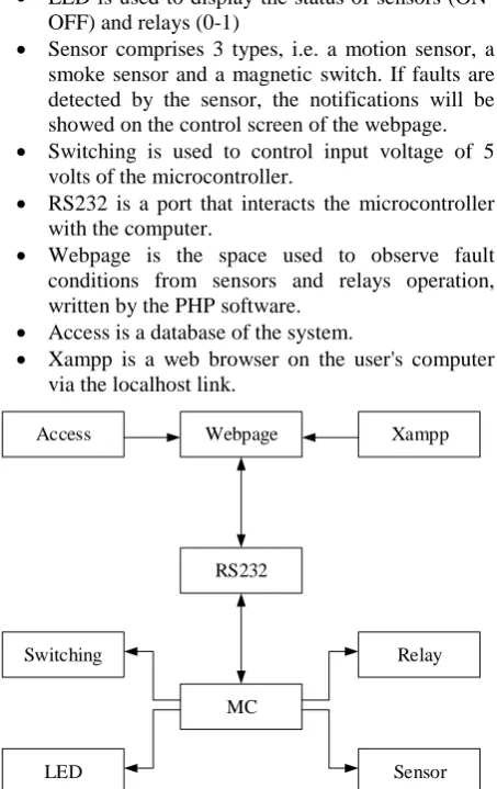
The box diagram of the designed security system based on communication technology with internet networks is shown in Fig. 1.
LED is used to display the status of sensors (ON-OFF) and relays (0-1)
Sensor comprises 3 types, i.e. a motion sensor, a smoke sensor and a magnetic switch. If faults are detected by the sensor, the notifications will be showed on the control screen of the webpage.
Switching is used to control input voltage of 5 volts of the microcontroller.
RS232 is a port that interacts the microcontroller with the computer.
Webpage is the space used to observe fault conditions from sensors and relays operation, written by the PHP software.
Access is a database of the system.
Xampp is a web browser on the user's computer via the localhost link.
MC RS232
Relay
Sensor Switching
LED
Webpage Xampp
Access
Figure 1. The box diagram of the designed security system.
The central computer is used to be an interface and processing of the proposed system. The Delphi software is used to control the devices using a microcontroller, which receives raw data from sensors via a serial communicate system. In addition, the status of the devices is displayed through a web page created from the PHP program. System operation is divided into two parts: hardware and software as shown in Fig. 2.
Hardware Software
Figure 2. The box diagram of the designed security system.
A. Hardware Part
Hardware consists of 8 relays and 3 sensors (a smoke sensor, micro switch, and a motion sensor), which is connected to the microcontroller. The raw data from the devices is sent via serial ports and recorded as database on the computer in order to process, control, and alert the security system automatically.
1) Relay. Fig. 3 shows the circuit diagram of a relay. When the relay’s coil is energized by electricity, a magnetic field will be occurred, resulting in movement of the movable contracts making a connection with a fixed contact, hence an electric current flow. Additionally, there are LED lamps to indicate the status of relays.
D9 IN4001 LED9
R25 1K
9013 R29
1K
R41 10
K V+
V-Relay 1
12V
NC RELAY-1
COM NO
1 2 3 Relay1 K9
Q9
Figure 3. The circuit diagram of a relay.
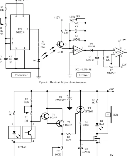
2) Motion. The motion sensor used is an infrared type, consisting of a transmitter circuit and a receiver circuit as shown in Fig. 4. When there is no an obstacle, the receiver circuit will not generate output signals. By contrast, if the sensor able to detect an object, there are signals generated from the output.
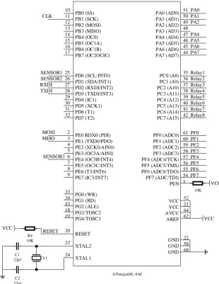
3) Motion. The smoke sensor circuit is shown in Fig. 5. When there is smoke occurring around the detected areas, the infrared light inside the sensor will be covered. Therefore, T1 and T2 transistors based on a Darlington connector will operate. The gate voltage of the SCR (T3) is high, causing voltage drop the MOSFET at T4 via the R4 resistance, thus BZ1 and LED lamps are activated.
4) ATmega64 microcontroller. A microcontroller is used to control all functions of the designed security system based on communication technology. In case study, the ATmega64 microcontroller of 64 pin is selected as shown Fig. 6.
B. Software Part
Q1 D2 1N4148
Receiver IC2a 3
2 1
L1 C3
RS 100K
POT
R4 2.2K
+12V
L14F
5 6
7 IC2b
R6 22K
R7 50K POT
+12V
8
4
C4 0.047 uF
-12V
IC2 = LN1458
D1
Transmitter 1 5 2 6
4 8
3 IC1 NE555
R3 220 Ohm
C2 0.01
uF C2
0.01 uF
R1 50K POT
R2 10K
+12V
Figure 4. The circuit diagram of a motion sensor.
2
1 3
4
H21A1 R1
1K
P1 1M
R2 100K
T1 BC547
T2 BC547
P2 100K
R3 100W C1
100uF/25V +
T3 BT169
R4 220W
C2 4u7/25V +
R5 1K
D1 Red
BZ1 +
0V +9V
Figure 5. The circuit diagram of a motion sensor.
III. EXPERIMENTAL RESULTS
This section presents experimental results of the designed security system based on communication technology, which are divided into the results of sensor status and relays operation; these are displayed thought a webpage.
A. Motion Sensor
PB0 (SS) PB1 (SCK) PB2 (MOSI) PB3 (MISO) PB4 (OC0) PB5 (OC1A) PB6 (OC1B) PB7 (OC2OCIC) PA0 (AD0) PA1 (AD1) PA2 (AD2) PA3 (AD3) PA4 (AD4) PA5 (AD5) PA6 (AD6) PA7 (AD7) PC0 (A8) PC1 (A9) PC2 (A10) PC3 (A11) PC4 (A12) PC5 (A13) PC6 (A14) PC7 (A15) PF0 (ADC0) PF1 (ADC1) PF2 (ADC2) PF3 (ADC3) PF4 (ADC4/TCK) PF5 (ADC5/TMS) PF6 (ADC6/TDO) PF7 (ADC/TDI) PEN PD0 (SCL/INT0) PD1 (SDA/INT1) PD2 (RXDI/INT2) PD3 (TXDI/INT3) PD4 (IC1) PD5 (XCK1) PD6 (T1) PD7 (T2)
PE0 RDX0 (PDI) PE1 (TXD0/PDO) PE2 (XCK0/AIN0) PE3 (OC3A/AINI) PE4 (OC3B/INT4) PE5 (OC3C/INT5) PE6 (T3/INT6) PE7 (IC3/INT7) VCC VCC AVCC AREF PG0 (WR) PG1 (RD) PG2 (ALE) PG3/TOSC2 PG4/TOSC1 GND GND GND RESET XTAL2 XTAL1 ATmega64L-8AI 10
CLK 11 12 13 14 15 16 17
SENSOR1 25 SENSOR2 26 RXDI 27 TXDI 28 29 30 31 32
MOSI 2 MISO 3 4 5 SENSOR3 6 7 8 9
51 PA0 50 PA1 49 PA2 48 47 PA4 46 PA5 45 PA6 44 PA7
35 Relay1 36 Relay2 37 Relay3 38 Relay4 39 Relay5 40 Relay6 41 Relay7 42 Relay8
61 PF0 60 PF1 59 PF2 58 PF3 57 PF4 56 PF5 55 PF6 54 PF7 1 10K VCC 33 34 43 18 19 20 23 24 52 21 64 62 22 58 68 VCC C2 22pf C1 22pf Y1 VCC R4 10K RESET
Figure 6. The circuit diagram of the ATmega64 microcontroller.
TABLE I. DISTANCE DETECTION OF A MOTION SENSOR
Number
Motion sensor ranges
Distance of 0.5 m Distance of 1 m Distance of 1.5 m Distance of 2 m Distance of 3 m
1 ON ON ON ON ON
2 ON ON ON ON OFF
3 ON ON ON ON ON
B. Smoke Sensor
Experimental results of a comparison between the normal and detectable state of the smoke sensor are shown in Table II. If the smoke is detected according to various test distance, the light on control screen will flash and the alarm status will be displayed. Thus, status at the bottom of the control screen become ON. The measurement of output voltage between the normal state and activated state of the sensor is 9 volts and 4 volts respectively.
TABLE II. DISTANCE DETECTION OF A SMOKE SENSOR USING
SIMULATED SMOKE
Number
Smoke sensor ranges Distance of 0.5 m Distance of 1 m Distance of 1.5 m Distance of 2 m
1 ON ON ON ON
2 ON ON ON ON
3 ON ON ON ON
C. Magnetic Switch
Table III presents the number of accuracy of magnetic switch operation – magnetic contactors are fixed.
TABLE III. MAGNETIC SWITCH OPERATION
Number 1 2 3 4 5 6 7
Status ON ON ON ON ON ON ON
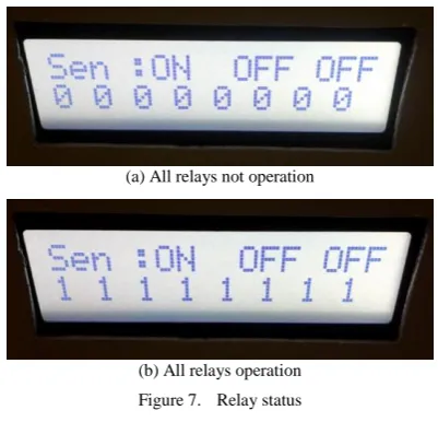
D. Relay
row shows status of all relays (8 relays); 0 is a normal state, 1 is operation state.
(a) All relays not operation
(b) All relays operation Figure 7. Relay status
IV. CONCLUSION
This paper presents the security system based on communication technology, dividing into two parts: the device control (relays and sensors) and the notification system on a webpage. In part of device operation, all of delays can operate ON-OFF effectively. There is LED display to indicate the status of the relays (0 or 1). The status for the sensors is ON-OFF, which works well together with the control system. For the notification, the status of three sensors is shown in the designed webpage on the server computer. If a fault takes place with the installed sensors, there is alarm on the webpage — ON status is shown. Thus, all installed sensors and the notification system can work realizable and effectively.
ACKNOWLEDGMENT
The authors wish to gratefully acknowledge financial support for this research from Faculty of Engineering, Saint John's University Research fund, Thailand.
REFERENCES
[1] Ş. Bahtiyar, O. Ermiş, A framework for trust assessment of security systems on flexible networks,” in Proc. IEEE 5th International Conference on Future Internet of Things
and Cloud, Prague, Czech Republic, 2017, pp. 177-182.
[2] C. Zhaozheng and H. Songyang, “Security system of ETC internet service,” in Proc. 4th International Conference on Information
Science and Control Engineering, Changsha, China, 2017, pp.
659-662.
[3] H. Pinggui and C. Xiuqing, “Design and implementation of campus security system based on internet of things,” in Proc.
International Conference on Robots & Intelligent System, Huai'an,
2017, pp. 86-89.
[4] S. Aswin and K. V. M. Prashanth, “Wireless office automation & security system - A novel approach,” in Proc. International
Conference on Recent Advances in Electronics and
Communication Technology, Bangalore, 2017, pp. 105-108.
[5] S. Tanwar, P. Patel, K. Patel, S. Tyagi, N. Kumar, and M. S. Obaidat, “An advanced internet of thing based security alert system for smart home,” in Proc. International Conference on
Computer, Information and Telecommunication Systems, Dalian,
2017, pp. 25-29.
[6] N. M. Kaliyamurthy, L. J. B. Andrews, and S. Shanmugasundaram, “Enhanced security in computer networks based on multilevel system and user intervention,” in Proc. International Conference on Signal Processing, Communication, Power and Embedded
System, Paralakhemundi, 2016, pp. 915-917.
Pairach Tanuphol is currently a lecturer at the department of electrical engineering, Faculty of Engineering, Saint John’s University, Bangkok, Thailand. His research interests are on transmission systems and Protection Relay.
Prayong Likitkarnpaiboon is currently a lecturer at the department of electrical engineering, Faculty of Engineering, Saint John’s University, Bangkok, Thailand. His research interests are on transmission systems and Protection Relay.