www.adv-radio-sci.net/8/101/2010/ doi:10.5194/ars-8-101-2010
© Author(s) 2010. CC Attribution 3.0 License.
Radio Science
Forward and backward RLS-DDCE processing in MIMO-OFDM
spatial multiplexing receivers
M. Muxfeldt, P. Beinschob, and U. Z¨olzer
Department of Signal Processing and Communications, Helmut-Schmidt-Universit¨at/University of the Federal Armed Forces Hamburg, Holstenhofweg 85, 22043 Hamburg, Germany
Abstract. In this paper we present a novel approach in fre-quency domain channel estimation technique. Our proposal is based on the recursive least squares (RLS) algorithm com-bined with the decision making process called decision di-rected channel estimation (RLS-DDCE). The novelty and key concept of this technique is the block-wise causal and anti-causal RLS processing that yields two independent pro-cessing of RLS along with the associated decisions. Due to the implemented low density parity check (LDPC) code the receiver operates with soft information, which enables us to introduce a new modification of the Turbo principle as well as simple addition of the a-posteriori log-likelihood ratios (LLRs). Although the computational complexity is increased by both of our approaches, the latter is relatively less com-plex than the earlier. Simulation results show that these im-plementations outperform the simple RLS-DDCE algorithm and yield lower bit error rates (BER) and more accurate chan-nel information.
1 Introduction
A widespread modulation technique used in today’s commu-nication systems is orthogonal frequency-division multiplex-ing (OFDM), which combines high spectral efficiency, ro-bustness against inter-symbol interference and an easy im-plementation using the fast Fourier transform (FFT). Com-bining the OFDM system with a multiple-input-multiple-output (MIMO) system, a MIMO-OFDM system is created, which results in a higher spectral efficiency and link reliabil-ity (B¨olcskei et al., 2002; Uysal et al., 2001).
Although the development of OFDM is already very ad-vanced, there still exists enough research potential in
MIMO-Correspondence to: P. Beinschob ([email protected])
OFDM. Today MIMO systems can be found in wireless local area network access points, WiMAX or some 3GPP specifi-cations.
Especially under bad transmission conditions with small signal-to-noise ratios (SNR) or high mobility, there are broad possibilities to improve the performance of MIMO-OFDM systems. High mobility involves a highly time-variant chan-nel, which causes the spectral efficiency to decrease. A so-lution to countervail this degradation is the enhancement of detailed knowledge of the channel state information (CSI).
An exceedingly important application area for improve-ment is in the domain of vehicle to vehicle (V2V) and vehi-cle to infrastructure (V2I) communication, where high rela-tive velocities create a time-variant channel combined with bad SNR scenarios due to obstacle obstructed communica-tion channels.
Receiver designs for MIMO-OFDM which make accept-able use of diversities are rare. There are few researches focusing on iterative receiver architechture (Akhtman and Hanzo, 2007b; Zhang et al., 2006; Liu et al., 2003; Sun et al., 2004), which exploit the Turbo principle with its iterative de-coding structure. Even though they result in higher compu-tational complexity these receivers seem to be promising in relation to BER performance.
Since the LDPC codes possess similar performance when compared to Turbo Codes, they are implemented in MIMO-OFDM systems as well (Lu et al., 2004). Also the combina-tion of the Turbo Principle and LDPC codes is under research (Salari et al., 2007).
S
o
u
rce
C
h
an
n
el
C
o
d
in
g
π
M S/PM
IM
O
C
o
d
in
g
IF
F
T
IF
F
T
IF
F
T
IF
F
T
F
F
T
F
F
T
F
F
T
F
F
T
M
IM
O
D
eco
d
in
g
M
−
1
π
−
1
C
h
an
n
el
D
eco
d
in
g
S
in
k
Channel Estimation
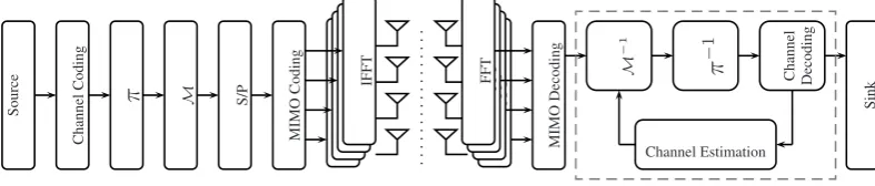
Fig. 1. General structure of the underlying system, represented for a 4×4 system.
The rest of the paper is organized as follows. The under-lying system model and structure are presented in Sect. 2, followed by the description of the RLS-DDCE algorithm in Sect. 3. Our novel approach with detailed information about the modified Turbo principle and summation of a-posteriori LLRs is presented in Sect. 4, respectively in Sects. 4.1 and 4.2. The paper is concluded by illustrating our simu-lation results in Sect. 5 and a conclusion in Sect. 6.
2 System model and structure
The vector of received valuesr at the time sample mof a MIMO system is the superposition ofL·nTpreviously sent samples and the currentnTsamples, whereL+1 is the length of the sampled channel impulse response andnTis the num-ber of transmit antennas. It is given by
r[m] = L
X
l=0
h[l,m] ·s[m−l] +w[m], (1)
where s[m]denotes the current vector of symbols of each of the transmit antenna, w is an identically, independently dis-tributed (iid) additive white Gaussian noise term and h[l,m]
is the MIMO channel matrix in delay and time domain, in-dexed withl respectivelym. The past sent samples are de-noted by s[m−l], forl6=0,l≤L. For simulations the data symbols of theK subcarriers are modulated by an inverse fast Fourier transform (IFFT). In simulations every value cor-responding to a transmit antenna of the resulting vectors is transmitted using the formula above.
In frequency domain the system model in Eq. (1) can be described as
r[n,k] =H[n,k] ·s[n,k] +w[n,k], (2) wherendenotes the time index of an OFDM symbol andk its subcarrier index. The vectorsr[n,k]and w[n,k]are of dimensionnR×1, s[n,k]of nT×1 and the matrix H[n,k] ofnR×nT, at whichnRis the number of receive antennas. In simulations the MIMO channel coefficientsHr,t[n,k], r= 1,...,nR, t=1,...,nT are modeled using the 3GPP spatial model which is developed to evaluate receiver algorithms in MIMO scenarios (3GP, 2008).
An overview of the implemented general system structure can be seen in Fig. 1. At first the bits for one OFDM trans-mission frame, arranged in vectorsuv,v=1,...,nc, withnc being the number of codewords, are LDPC (MacKay, 1999) encoded and implemented according to Richardson et al. (2001), using the coding matrix G
uv,c=G·uv. (3)
The vectorsuv,ccontain the regular information bitsuhand the parity bits uf, h=1,...,ns, f=1,...,np, where ns de-notes the information length andnpdenotes the number of parity bits. Following the transmitter scheme the systematic and parity bits are then interleaved and quadrature amplitude modulated as shown byπ respectivelyMin Fig. 1. At this stage the generated symbols are serial to parallel converted and MIMO encoded, which is performed by spatial multi-plexing by multiplying with the unity matrix in the under-lying system, resulting in vectorss[n,k], which are symbol wise fed into the IFFT, one for each transmit antenna.
In the receiver, the superposed received signals are trans-ferred back into the frequency domain with the help of a FFT, resulting in the vectorsr[n,k]of Eq. (2). Subsequently the RLS-DDCE algorithm is performed on each of the OFDM symbols. The demodulator produces soft information in form of a-priori LLRs,L(uh), which are defined as the logarithm of the ratio of the probabilities of a bit uh being 0 or 1 . These LLRs are LDPC decoded, producing the estimated a-posteriori LLRs at the output of the LDPC decoder:
L(uh|y)=ln P (u
h=1|y) P (uh=0|y)
, (4)
where y is the sequence of received bits for one codeword. Together with the estimated a-posteriori LLRs the LDPC de-coder produces the parity check sum (PCS):
A·uv,c≡γ, (5)
C
au
sal
R
L
S
P
ro
ces
si
n
g −M
1
π
−
1
C
h
an
n
el
D
eco
d
in
g
Channel Estimation
M
em
o
ry
A
n
ti
cau
sal
R
L
S
P
ro
ces
si
n
g
M
−
1
π
−
1
C
h
an
n
el
D
eco
d
in
g
Channel Estimation
M
em
o
ry
Further Processing of Information
final RLS
Sink
Fig. 2. Novel approach in forward and backward RLS-DDCE processing implemented on the receiver side of the system depicted in Fig. 1.
When the PCS is not zero, the soft information of the a-posteriori LLRs is used to transform the received symbols into the transmitted symbols. The symbols gained by either of the strategies are then used to calculate an estimate of the channel transfer function vectorsH˜[n,k]via the RLS algo-rithm, which is further explained in Sect. 3.
The BER is calculated on the basis of the equalized re-ceived symbols. These symbols are therefore decoded,de-interleaved and decided on a hard basis.
Figure 2 shows the structure of our novel approach to the channel estimation and is explained in Sect. 4.
3 RLS-DDCE
The RLS algorithm as described in Akhtman and Hanzo (2007a) is suitable for tracking a communication channel as it computes an estimate of the current channel matrix
˜
H[n,k]upon arrival of new received data r[n,k]and con-verges within just a few OFDM symbols.
The introduced forgetting factorξ associates an exponen-tial weighting of the past transmitted signals onto the current channel factor. Therefore it can be used to adapt to the time-variant channel conditions.
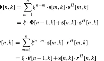
For calculating the channel transfer function the autocor-relation matrix (6) of the transmitted signals and the cross-correlation matrix (7) of the transmitted and received signals are needed. Initialisation of both matrices is performed by using the identity matrix I.
8[n,k] = n
X
m=1
ξn−m·s[m,k] ·sH[m,k]
=ξ·8[n−1,k] +s[n,k] ·sH[n,k] (6)
θ[n,k] = n
X
m=1
ξn−m·s[m,k] ·rH[m,k]
=ξ·θ[n−1,k] +s[n,k] ·rH[n,k] (7) Following the development of the RLS algorithm the solution for calculating the channel factors ends up in the matrix form of the normal equation, that can be formed to calculate the channel factors by inverting the autocorrelation matrix, as can be seen in the following equation:
˜
H[n,k] =8−1[n,k] ·θ[n,k] H
. (8)
1 . . . NP 1 2 3 . . . Nd 1 . . . NP 1 2 3 . . . Nd
preamble
bit-interleaved OFDM-symbols frame 1
preamble
bit-interleaved OFDM-symbols frame 2
Forward RLS-DDCE Forward
RLS-DDCE
Backward RLS-DDCE
Fig. 3. Frame structure for proposed MIMO-OFDM RLS-DDCE
Forward and Backward Filtering with re-use of next and previous frame preambles.
The inversion of the autocorrelation matrix can be avoided by using the matrix inversion lemma, the description of which is omitted here.
Summation of rank-1 matrices in Eqs. (6) and (7) is avoided by starting each transmission frame with a training sequence of known pilot symbols, as the matrices have full condition after a few summations. The transmitted symbols are known in the receiver and the channel transfer function estimatesH˜[n,k]can instantly be calculated. The symbols following the pilot symbols have to be decided in the re-ceiver, for that reason the received symbols are equalized, decoded and detected before calculation of the channel fac-tors.
4 Forward and backward RLS processing
The RLS-DDCE algorithm provides the receiver with infor-mation on the channel and also results in the transmitted sig-nals. Due to the uncertainty in the decision making process it is prone to error propagation which might lead to a large amount of errors and entirely destroyed subcarriers.
Our novel proposal for this is to perform the RLS algo-rithm twice, in causal and anti-causal direction, which uses block-wise processing of received data, as shown in Fig. 3. This is done independently of each other since the additional information gained from that technique can be evaluated to eliminate errors and correct wrong decisions.
LDPC Decoder
LDPC Decoder
→total PCS= 0
→∆σ2<0.03
⇒break
+ +
−
− − −
Lmax(uh|y) yh,1
yf,1
yh,2
yf,2
L1(uh|y)
L2(uh|y)
L2(uh) =L1,e(uh) L1(uh) =L2,e(uh)
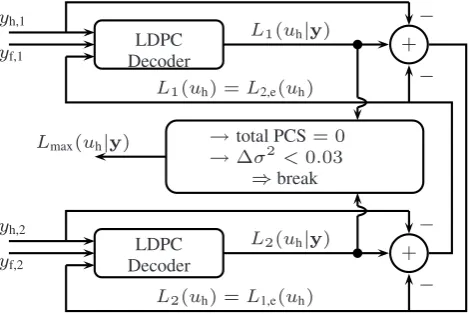
Fig. 4. Modified Turbo principle.
by soft demodulation and decoding, depicted by C−1 in Eq. (9). The right part of the figure processes the received data anti-causal wise, Eq. (10), where the length of the pilot symbols is denoted byNP and the data length byNd. This routine can be described as:
L1(uh|y)=C−1(M−1{H†[n,k]r[n,k]}), (9)
L2(uh|y)=C−1(M−1{H†[ν,k]r[ν,k]}), (10) ν=(NP+Nd)−n,
where H†denotes the pseudo-inverse of the channel matrix andνthe anti-causal time index.
The gained information in the form of a-posteriori LLRs (4) is passed on for further evaluation. Due to this post-evaluation of the first two RLS processing, depending on the SNR and actual channel conditions, some of the codewords in the receiver can be considered as being correct. These codewords provide additional reliable information for the fi-nal RLS processing and will not be decided again. In case the post-evaluation does not result in any correct codewords, the final RLS processing is performed using the information of either the causal or anticausal RLS processing.
An important part of the proposed approach is the applica-tion of soft informaapplica-tion, which is used to calculate the trans-mitted symbols in case of incorrect decoding. This additional usage of the soft information is exploited to calculate the BER, contrary to the normal RLS-DDCE algorithm.
The underlying frame structure only provides a training sequence at the beginning of each frame, and therefore the training sequence of the subsequent transmission frame can be used for the anti-causal RLS processing. Exploiting the incremental overhead twice comes at no additional overhead cost, but results in an additional channel information gain. Figure 3 gives an idea of the double usage of the pilot sym-bols.
4.1 Modified Turbo principle for forward and back-ward RLS processing
For our purpose the original Turbo principle of Berrou et al. (1993) and Berrou and Glavieux (1996), nicely explained by Hanzo et al. (2002), is changed, as presented in Fig. 4. We totally ignore the encoding part of the original Turbo Coding and solely perform the normal LDPC coding as presented in Sect. 2, which will lead to the combination of LDPC and Turbo decoding in the receiver.
On the receiver side we retain the Turbo decoding lay-out, though we change the inputs to the component decoders. As the RLS algorithm is processed in causal and anti-causal manner the soft information of the received bitsyhis avail-able twice,yh,1 andyh,2. The availability of two different inputs, which are supposed to be the same under perfect con-ditions, replaces the usage of two different codes. The ex-trinsic information is created and exchanged in the same way as in the original Turbo principle:
Le(uh)=L(uh|y)−L(uh)−Lc·yh, (11) whereLcdenotes the channel reliability.
Our proposed Turbo decoding is performed twice, starting with the soft information from the causal RLS first, followed by the anti-causal information with the adequate extrinsic in-formation (12) and vice versa (13).
L1(uh|y)⇒L1,e(uh)=L2(uh)⇒L2(uh|y) (12)
L2(uh|y)⇒L2,e(uh)=L1(uh)⇒L1(uh|y) (13) In our proposal we use the break criterion provided by Robertson (1994), which evaluates the variance of the a-posteriori LLRs. This is sensible as this criterion de-scribes the alteration of the a-posteriori LLRs and the it-eration breaks when subsequent a-posteriori LLRs do not change more than 0.03.
Nevertheless we also include an additional break criterion in order to avoid unnecessary iterations. In case the PCS for all codewords of either the causal or anti-causal RLS are zero, which is mostly the case for high SNR, the iteration of the Turbo decoding will not even start. The two break criteria are also shown in Fig. 4.
The comparably large codeword distance of LDPC codes (MacKay, 1999) can be used to evaluate the performance of certain iteration steps. A PCS of zero is likely to be equiva-lent to an error free codeword. And in addition, simulations have shown that a small total PCS over all codewords is con-nected to a lower BER.
B
E
R
SNR in dB 10-3
10-2 10-1 100
6 9 12 15 18 21
⊗
⊗
⊗
⊗
⊗
⊗
×
×
×
×
×
×
*
*
*
*
*
*
⊗ ⊗ ⊗
⊗
⊗
⊗
×
×
×
×
×
×
*
*
*
*
*
*
1
.67m/s 25m/s
*
RLS-DDCE*
RLS-DDCE⊗ Summation ⊗ Summation
×
Turbo×
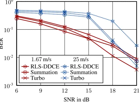
TurboFig. 5. BER for different SNR at velocities of 1.67 m/s and 25 m/s.
the a-posteriori LLRsLmax(uh|y)that are to be further pro-cessed:
nc X
m=1 pv,fw≤
nc X
m=1
pv,bw⇒Lmax(uh|y)=L2(uh|y), (14)
nc X
m=1 pv,bw≤
nc X
m=1
pv,fw⇒Lmax(uh|y)=L1(uh|y), (15)
wherepv,fwrespectivelypv,bwdescribe the PCS of the code-word v after the second LDPC decoder operating on the anti-causal respectively anti-causal data.
After the iteration the RLS algorithm is again processed in causal or anti-causal direction, depending on the origin of Lmax(uh|y). The correct codewords are determined by codewords with a PCS of zero.
4.2 Summation of a-posteriori LLRs
Our second approach to improve the channel estimation is to simply sum up the a-posteriori LLRs from the forward and backward RLS processing:
Lmax(uh|y)=L1(uh|y)+L2(uh|y). (16) This, in comparison to the modified Turbo principle, has less computational complexity and still corrects a large amount of errors.
The key issue behind this idea is the availability of the soft information, which is presented by the sign and magnitude of the LLRs. Out of the LLRs, the probability of a bit being a 1 or 0 can easily be computed:
P (uk=1)=
1 1+exp(−L(uh))
, (17)
P (uk=0)=
1 1+exp(+L(uh))
. (18)
Table 1. MIMO-OFDM system parameters.
Parameter Value
carrier frequency 2.412 GHz
channel bandwidth 20 MHz
number of subcarriers K 128
number of OFDM symbols p. frame 576
number of pilot symbols p. frame 32
channel model 3GPP SCM
channel order L 6
norm. Doppler freq.fd,n 0, . . . , 1.35×10⁻³
equiv. velocityvin m/s 0, . . . , 25
LDPC design code rate 1/2
In the case when both of the RLS processing results in the same decided bits, the summation of the LLRs will not change the decisions, but enhances the reliability of the right decision. When the RLS processing decide on different bits, the larger magnitude of the soft information will determine the final bits.
The reliable codewords to conduct the final RLS process-ing are determined by comparprocess-ing the hard decided bits, based on the a-posteriori LLRs after the summation, with the hard decided bits of the a-posteriori LLRs before the summation. A codeword is considered to be reliable when all a-posteriori LLRs of a certain codeword do not change due to the sum-mation. To ensure the correctness of that codeword the total PCS for the codeword has to be zero, regardless of whether it is based on the causal or anti-causal RLS.
5 Simulation results
The simulation was performed on a 4×4 MIMO-OFDM sys-tem with the simulation parameter given in Table 1. For the modulation, a 4-QAM was taken so that an OFDM symbol consisted of 1024 bits. The calculated frame duration based on the paramters resulted in 3.86 ms.
The forward, backward and final RLS processing used the simple zero forcing equalizer due to computational complex-ity and retention of soft information. Thereby the resulting BER was not as small as possible, but the operating principle and the improvements due to our new approach were demon-strated.
Simulations were done for several velocities, ranging from 0 m/s, for comparison, to 25 m/s, suitable for a micro urban cell as simulated by the channel model. The range of inter-esting SNR values lied between 6 dB and 21 dB.
The forgetting factorξ was chosen according to (Akhtman and Hanzo, 2007a) with a value of 0.7, so that the algorithm worked fine over a large range of velocities.
B
E
R
Velocity in m/s
10-3
10-2
10-1
100
0
.0 4.1 8.3 12.5 16.6 20.8 25.0
* * *
*
*
*
*
*
* * *
*
*
*
*
*
⊗ ⊗ ⊗ ⊗
⊗ ⊗ ⊗ ⊗
⊗ ⊗ ⊗ ⊗ ⊗ ⊗ ⊗ ⊗
× × × ×
× × × ×
× × × × × × × ×
18dB SNR 21dB SNR
*
RLS-DDCE*
RLS-DDCE⊗ Summation ⊗ Summation
× Turbo × Turbo
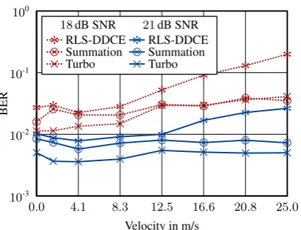
Fig. 6. BER for different velocities at 18 dB SNR respectively 21 dB
SNR.
for both velocities. For smaller SNR, up to about 15 resp. 19 dB, the summation of a-posteriori LLRs dominated the BER performance. The Turbo principle was slightly worse, but increased in performance for higher SNR values. For small SNR values the receiver did not yield correct code-words, so the performance increase in comparison to the sim-ple RLS-DDCE algorithm was solely due to the extended soft information evaluation of the final RLS processing. In addi-tion the summaaddi-tion used the added a-posteriori LLRs for the BER evaluation in low SNR regions, which explains the bet-ter performance for small SNR values. For the upper SNR range the Turbo principle worked better due to the larger amount of correct codewords, which resulted in a smaller BER.
The simulation results in relation to the velocities are shown in Fig. 6. The RLS-DDCE algorithm again performed worst. For the SNR of 18dB the summation was comparable to the modified Turbo principle for velocities above 12.5 m/s. In case of lower velocities and for the entire velocity range at 21dB the modified Turbo principle performed better, because of the available number of correct codewords.
In order to evaluate the channel estimation the normalized mean squared error (NMSE) is applied:
NMSE= N−1
P
n=0
K−1 P
k=0
nT P
t=1
nR P
r=1
Hr,t[n,k] − ˜Hr,t[n,k] 2
N−1 P
n=0
K−1 P
k=0
nT P
t=1
nR P
r=1
Hr,t[n,k] 2
(19)
Figure 7 shows the NMSE in relation to the velocities for a SNR of 18 and 21 dB. For 21 dB SNR the behaviour was the same as for the BER, the modified Turbo principle resulted in the lowest NMSE values. The results were different for 18 dB SNR, where the summation of a-posteriori LLRs per-formed the better channel estimation. The values at 1.67 m/s and 20.8 m/s for 18 resp. 21 dB for the summation and Turbo
N
M
S
E
Velocity in m/s
10-2
10-1
100
101
102
0
.0 4.1 8.3 12.5 16.6 20.8 25.0
* *
*
*
*
*
*
*
* * *
*
*
*
*
*
⊗ ⊗
⊗ ⊗
⊗ ⊗ ⊗ ⊗
⊗ ⊗
⊗ ⊗ ⊗ ⊗ ⊗ ⊗
× × × × × × × ×
× × × ×
× ×
× ×
18dB SNR 21dB SNR
*
RLS-DDCE*
RLS-DDCE⊗ Summation ⊗ Summation
× Turbo × Turbo
Fig. 7. NMSE for different velocities at 18 dB SNR respectively
21 dB SNR.
principle presented runaway values due to insufficient chan-nel realisations.
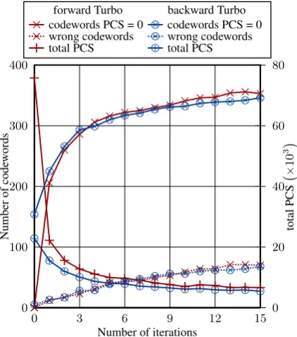
Figure 8 shows the iterative behavior of the implemented Turbo principle for a SNR of 18 dB and a velocity of 8.33 m/s. The figure nicely depicts how the number of code-words with a total PCS of zero increased with increasing number of iterations, for the forward and backward iteration. Along with it the number of wrong codewords, codewords with PCS of zero and biterrors, also rose. This was due to the LDPC decoder, which ran into wrong codewords due to the exchange of extrinsic information. As one can see, the curve’s slope for the total PCS was flattening with increasing iterations, so that the variance break criterion became active at one point and stopped the iteration. In case the final RLS processing is able to make better decisions with more reliable channel information, then the number of iterations should not be too large in order to avoid incorrect codewords. In addi-tion Fig. 8 presents the difference between the causal and anticausal iteration direction, as can be seen at the starting values of the curves.
6 Conclusion
N
u
m
b
er
o
f
co
d
ew
o
rd
s
Number of iterations
to
ta
l
P
C
S
×
10
3
0 100 200 300 400
0 3 6 9 12 15
0 20 40 60 80
⊕ ⊕
⊕ ⊕ ⊕ ⊕ ⊕ ⊕ ⊕ ⊕ ⊕ ⊕ ⊕ ⊕ ⊕ ⊕
+
+
+
+ + + + +
+ + + + + + + +
× ×
× ×
× × × × × ×
× × × × × ×
⊗ ⊗
⊗
⊗ ⊗ ⊗ ⊗ ⊗
⊗ ⊗ ⊗ ⊗ ⊗ ⊗ ⊗ ⊗
× × × × ×
× × × × × × × × × × ×
⊗ ⊗ ⊗ ⊗ ⊗ ⊗
⊗ ⊗ ⊗ ⊗ ⊗ ⊗ ⊗ ⊗ ⊗ ⊗
forward Turbo backward Turbo
× codewords PCS = 0 ⊗ codewords PCS = 0
× wrong codewords ⊗ wrong codewords
+
total PCS ⊕ total PCSFig. 8. Iterative behavior of the Turbo principle showing the number
of correct codewords, wrong codewords and total PCS for the for-ward and backfor-ward Turbo iteration, at a SNR of 18 dB and 8.33 m/s.
corrects a certain amount of wrong decided symbols. The performance increase for the NMSE is comparable to the BER performance and results in a better channel estimation for the proposed approaches.
References
3GPP: Spatial channel model (SCM) for Multiple Input Multiple Output (MIMO) simulations, TR 25.996, 2008.
Akhtman, J. and Hanzo, L.: Advanced Channel Estimation for MIMO-OFDM in Realistic Channel Conditions, IEEE Inter-national Conference on Communications, 2007, ICC ’07, pp. 2528–2533, doi:10.1109/ICC.2007.418, 2007a.
Akhtman, J. and Hanzo, L.: Iterative Receiver Architectures for MIMO-OFDM, in: Wireless Communications and Network-ing Conference, 2007.WCNC 2007, IEEE, pp. 825–829, doi: 10.1109/WCNC.2007.157, 2007b.
Berrou, C. and Glavieux, A.: Near optimum Error Correcting Cod-ing and DecodCod-ing: Turbo-Codes, IEEE Transactions on Commu-nications, 44, 1261–1271, 1996.
Berrou, C., Glavieux, A., and Thitimajshima, P.: Near Shannon limit error-correcting coding and decoding: Turbo-codes (1), IEEE International Conference on Communications, 2, 1064– 1070, 1993.
B¨olcskei, H., Gesbert, D., and Paulraj, A.: On the Capacity of OFDM-Based Spatial Multiplexing Systems, IEEE Transactions on Communications, 50, 225–234, 2002.
Hanzo, L., Liew, T. H., and Yeap, B. L.: Turbo coding, turbo equali-sation, and space-time coding for transmission over fading chan-nels, Wiley, Chichester, 2002.
Liu, H., Wang, X., and Xiong, Z.: Iterative receivers for OFDM coded broadband MIMO fading channels, IEEE Workshop on Statistical Signal Processing, pp. 355–358, 2003.
Lu, B., Yue, G., and Wang, X.: Performance Analysis and Design Optimization of LDPC-Coded MIMO OFDM Systems, IEEE Transactions on Signal Processing, 52, 348–361, 2004.
MacKay, D.: Good error-correcting codes based on very sparse ma-trices, IEEE Transactions on Information Theory, 45, 399–431, doi:10.1109/18.748992, Mar 1999.
Richardson, T. J., Shokrollahi, M. A., and Urbanke, R. L.: De-sign of capacity-approaching irregular low-density parity-check codes, IEEE Transactions on Information Theory, 47, 619–637, doi:http://dx.doi.org/10.1109/18.910578, 2001.
Robertson, P.: Illuminating the structure of code and decoder of parallelconcatenated recursive systematic (turbo) codes, IEEE Global Telecommunications Conference, 3, 1298–1303, 1994. Salari, S., Ardebilipour, M., Ahmadian, M., Cances, J., and
Megh-dadi, V.: Turbo Receiver Design with Carrier-Frequency Offset Estimation for LDPC-Coded MIMO OFDM Systems, Interna-tional Conference on Advanced Communication Technology, 3, 1911–1915, 2007.
Sun, S., Wu, Y., Li, Y., and Tjhung, T.: A novel iterative receiver for coded MIMO OFDM systems, IEEE International Conference on Communications, 4, 2473–2477, 2004.
Uysal, M., Al-Dhahir, N., and Georghiades, C.: A SpaceTime Block-Coded OFDM Scheme for Unknown Frequency-Selective Fading Channels, IEEE Communications Letters, 5, 393–395, 2001.