Please cite this article as: L.Ke and YC. Liu, Modeling and Simulation of Variable Frequency Pump Control Fatigue Test Machine,International Journal of Engineering (IJE), TRANSACTIONS A: Basics..Vol. 29, No. 1, (January 2016) 96-102
International Journal of Engineering
J o u r n a l H o m e p a g e : w w w . i j e . i rModeling and Simulation of Variable Frequency Pump Control Fatigue Test Machine
L. Ke*, YC. Liu
Zhejiang Industry Polytechnic College, Shaoxing-312000, China
P A P E R I N F O
Paper history:
Received 04December 2015
Received in revised form 10January 2016 Accepted in 28 January 2016
Keywords:
High-speed Maglev Train Variable Frequency Hydraulic
Fatigue Test Machine SIMULINK
A B S T R A C T
High-speed maglev train is considered an ideal vehicle in the 21st Century. The travel mechanism as an important part of the train, bears and delivers a variety of vertical and horizontal alternating load in operation. It affects the operation safety of the train directly, so key components of the travel mechanism should be under fatigue strength test by fatigue test machine. The paper proposed a variable frequency pump control fatigue test machine for high-speed maglev train. It simplified the structure and improved the stability and reliability by using variable frequency pump control technology to regulate the velocity of the motion of hydraulic cylinder. Introducing the operating principle of the system, established the simulation model including frequency converter, electromotor and hydraulic system. The system performance in the cases of variable load and variable speed is analyzed with the SIMULINK of MATLAB. The system is verified correct and feasible by comparing simulation results with the actual situations. Finally, control performance of the model system was optimized by using PID closed-loop controller as well. The variable frequency pump control fatigue test machine achieved high response and high energy efficiency, so it is suitable for fatigue test application.
doi: 10.5829/idosi.ije.2016.29.01a.13
NOMENCLATURE
np Rotational speed of Three-phase alternating current asynchronous motor Dp Capacity of pump
f1 Frequency of power supply pp Outlet pressure of pump
s Slip of electric motor ηpm Mechanicalefficiency of pump
mp Pole pairs of electric motor Qp Outputflow of pump
Eg Valid values of each phase electromotive force Qlp Leakage of pump
Ψg Air gap flux linkage Ql Flow which emerged by oil compressibility inside the pump
U1 Stator phase voltage μt0 Dynamicviscosity of hydraulic oil when the temperature is t0
UN Rated voltage of motor λ Viscosity-temperature coefficient of hydraulic oil
fN Rated frequency of motor t Temperature of hydraulic oil
U0 Low-frequency voltage compensation value βe Bulk modulus of hydraulic oil
Tn Electromagnetictorque of asynchronous motor Qc Input flow of hydrauliccylinder
ω1 Motor stator angular frequency A Area of piston big end of hydrauliccylinder
R1 Stator resistance v Speed of cylinder rod
R2’ Rotor resistance which converts to the stator side Clc Leakage coefficient of hydrauliccylinder
L1 Stator leakage inductance Vm Volume from hydraulic pump to hydrauliccylinder
L1’ Rotor leakage inductance which convert to the stator side m Total mass of the hydraulic rod and load
JT Moment of inertia of asynchronous motor Bc Viscousdampingcoefficient of hydraulic cylinder
np Rotational speed of t asynchronous motor FLc Load of fatigue test machine
TL Loadtorque of asynchronous motor kuf Voltage frequency coefficient of the controller
BT Damping coefficient of the motor shaft
*Corresponding Author’s Email: [email protected]( L.Ke)
1. INTRODUCTION
The high-speed maglev train has the advantage of energy saving, safe, comfortable and good line adaptability, and become one of the most competitive public transport in the future. The travel mechanism is the most significant part of the high-speed maglev train with complex working conditions, as the travel mechanism is the loaded platform of the train, and the working platform of traction and turning [1]. It influenced the whole performance of maglev trains. Improving and optimizing the structure of the travel mechanism by fatigue testing key components of the travel mechanism and analyzing the test result is very useful and important [2-4]. Hydraulic transmission used in fatigue test gig areas has the advantages of high energy density, steady transmission and steady transmission. Traditional fatigue test gigs change executers’ speed by adjusting electro-hydraulic servo valves or proportional solenoid directional control valves [5], which will cause massive throttle loss and overflow loss [6, 7]. So, the traditional fatigue test gigs with throttle control have the disadvantages of low efficiency in power, complicate structure, high requirement for oil quality and expensive to repair. Especially, it’s impossible to change electric motor’s speed when the fatigue test gig is running. Motor runs very fast although the requirement of system volume is small even the machine is in stand-by mode. It cause seriously wear of the electric motor and hydraulic motor, shorten lifespan of fatigue test machine [8], and will made a loud noise as well.
The output flow rate of ration pump can be governed by adjusting the frequent of electrical power, accordingly [9], hydraulic cylinder’ speed of fatigue test gig can be governed by using frequency control technology in order to satisfy the system. The article introduces the principle of variable frequency pump control hydraulic speed governing system, established the simulation model, and analyzed the system performance base on SIMULINK of MATLAB. The system is verified correct and feasible by the simulation, control performance of the model system is optimized by using PID controller as well.
2. THE PRINCIPLE OF THE FATIGUE TEST MACHINE HYDRAULIC SYSTEM
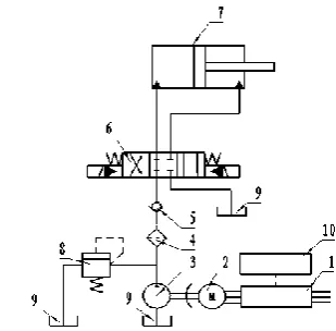
The principle of the fatigue test gig hydraulic system can be seen in Figure 1. Frequency converter transforms 380V/50Hz industrial frequency source supply into three-phase ac power with specific frequency and specific voltage for asynchronous motor. Motor drives the ration pump with determined speed to output hydraulic oil with determined flow. Finally, hydraulic oil drives piston rod of hydraulic cylinder to do fatigue
test through the filter, the check valve and the electric-hydraulic commutating valve. Hydraulic oil from exit of the dual-action telescopic cylinder goes back to the oil tank.
Figure 1. The principle of fatigue test gig hydraulic System: 1- frequency converter 2- three-phase alternating current asynchronous motor 3- ration pump 4-filter5- check valve 6- electric-hydraulic commutating valve 7- dual-action telescopic cylinder 8- relief valve9- oil tank, 10- speed controller
The system eliminated throttle loss and overflow loss by adopting an electric-hydraulic commutating valve to replace the electro-hydraulic servo valve, improved energy utilization, simplified the system’s structure, enhanced the reliability. Especially, motor can reduce rotate speed with executor’s speeddroop automatically when requirement of system’ volume is small or in stand-by situation.
3. MODELS OF VARIABLE FREQUENCY PUMP CONTROL FATIGUE TEST MACHINE
3. 1. Link of Frequency Converter The speed of three-phase alternating current asynchronous motor can be described as
(1)
Equation (1) shows that the rotational speed of three-phase alternating current asynchronous motor is proportional to the frequency of power supply. Frequency converter can control the asynchronous motor to attain stepless speed regulating by changing the frequency of power supply. The air gap flux linkage should be kept constant during the course of varying speed of the motor in order to make full use of asynchronous motor. The air gap flux linkage satisfies the following equation [10]:
(2)
1 1
60 (1 ) / (1 )
p p
n f s m n s
Equation (2) shows that the air gap flux linkage will be kept constant as long as Eg/f1 is constant. However, it
is difficult to detection and control, stator phase voltage can be considered equal to the valid values of each phase electromotive force, as:
1 g 4.441 g
U E f (3)
The pressure and frequency ratio should keep constant when output frequency of controller is lower than fundamental frequency, U1/f1=Const. However,
when the output frequency of controller is low, stator magnetic indicator leakage resistance voltage drop ratio increased,so the assumptionU1≈Eg is invalid, the
voltage U1 should be raised in order to compensate
stator voltage drop. When output frequency of controller lower than fundamental frequency, the voltage and frequency of motor stator satisfied the equation as follows
1 1 0
N
N
U
U f U
f
(4)
When output frequency of controller is higher than fundamental frequency, the stator voltage couldn’t be raised as the limitation of saturation of magnetic, so motor run in a weak magnetic state.
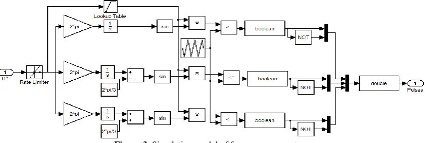
Synthesize the above analysis, the functional diagram of frequency converter of three-phase alternating current asynchronous motor is set up, as shown in Figure 2.
Frequency converter consisted of the acceleration and deceleration time setting, U/fcurve, integrator, SPWM modulation and inverter. f1* is the signal of
frequency given by system, the acceleration and deceleration time setting limits the acceleration of asynchronous motor, in order to avoid the enormous impulsion to motor’s stator current and torque. Voltage magnitude of SPWM modulating wave can be obtained according to f1 and U/f curve, U/f maintain constant
when f1 is below the fundamental frequency, while
stator voltage equals to rated voltage when f1 is above
the fundamental frequency.
The phase angle of modulation wave θU can be
obtained by integrating f1 by the integrator. SPWM
produces sine pulse width modulation driving signals to control inverter according to the voltage magnitude U and the phase Angle of Modulation wave θU, so the
rotate speed of asynchronous motor can be governed. The simulation model of frequency converter based on SIMULINK is shown in Figure 3.
3. 2. Link of Asynchronous Motor According to principle of electromotor, electromagnetictorque of asynchronous motor satisfies the following equation [11]:
2
1 1 2
2 2 2 2
1 1 2 1 1 2
3 ( )
( ) ( )
n p
U s R
T m
sR R s L L
(5)
Torque balance equation of asynchronous motor is shown below
2 2
60 60
p
T n L T p
dn
J T T B n
dt
(6)
The loadtorque of asynchronous motor from Equation (6) is input torque of constant delivery pump, considering the loss of mechanical transmission, the loadtorque of asynchronous motor is given as
p p L
p m
D p T
(7)
Figure 2. The functional diagram of frequency converter of three-phase alternating current asynchronous motor
Figure 4. Simulation model of asynchronous motor
According to Equations (5)-(7), simulation model of asynchronous motor can be established, as shown in Figure 4.
3. 3. Link of Hydraulic The output flow of hydraulic pump is related to rotational speed of electric motor and affected by leakage flow of pump. Liquid-flow equation of the pump outlet is shown below [12]
2 60
p p p lp l
Q D n Q Q (8)
The leakage of pump can be expressed as [13]
0 0
( ) lp p
lp t t
t
C p
Q
e
(9)
The flow which emerged by oil compressibility inside the pump can be expressed as follows
2
/ 60
l p p p e
Q p n D (10)
According to Equations (8)-(10), the liquid-flow equation of the pump can be rewritten as
( 0) 0 2
(1 )
60
p lp p
p p p t t
e t
p C p
Q D n
e
(11)
While the input flow of hydrauliccylinder is
c ( 0)
0 1+ p lc t tp
e t
p C p
Q Av
e
( ) (12)
According to flow continuity equation, following equation can be obtained
m p
p c e
V Avdt dp
Q Q
dt
(13)By substituting Equation (11) and Equation (12) into Equation (13), flow continuation equation of hydraulic link can be obtained.
( 0) ( 0)
0 0
2
(1 ) 1+
60 p m
e
p p lp p lm p
p p t t t t
e e t t
dp V
dt
p p C p C p
D n A v
e e
(14)
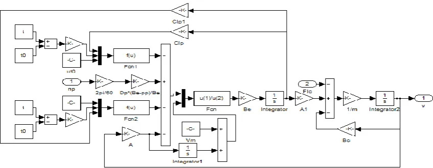
According to the second law of Newton, the force equilibrium equation of hydraulic cylinder is as below
p c Lc dv
m Ap B v F
dt (15)
According to Equations (14)-(15), simulation model of hydraulic link with SIMULINK of MATLAB can be established [13-15] as shown in Figure 5.
4. SIMULATION OF VARIABLE FREQUENCY PUMP CONTROL FATIGUE TEST MACHINE
4. 1. Simulation of Open Loop System
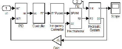
Connected and packaged simulation models of the frequency converter, the asynchronous motor, the hydraulic link with SIMULINK, open loop system of variable frequency pump control fatigue test machine was set up, as shown in Figure 6.
Figure 6. Open loop system of variable frequency pump control fatigue test machine
Figure 7. Hydraulic pressure of system
Figure 8. Hydraulic pressure of system
Figure 9. Speed curve of hydraulic cylinder
Figure 10. Structure of proportion integration differentiation controller
Input of open loop system simulation model is voltage signal of frequency converter uc, the relation
between voltage signals and frequencysignal is shown as follows
*
1 uf c
f k u (16)
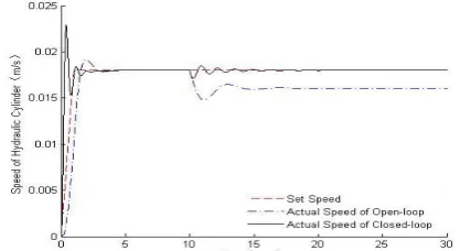
Simulation analysis of open loop system was carried out under the condition of constant speed and variable load. The set speed of hydraulic cylinder is 0.018 m/s, and load of the system is 0N Within 10 seconds and increase to 500N 10 seconds later. Figure 7 shows the simulation results of load and hydraulic pressure of system. Figure 8 shows the set speed and actual speed of hydraulic cylinder.
When the load of system is 0N,the deviation between set speed and actual speed of hydraulic cylinder is small, steady-state deviation is less than 1%, when the load of system increases to 500N, actual speed of hydraulic cylinder is about 0.016 m/s, and steady-state deviation is more than 11%, so the steady-steady-state deviation of hydraulic cylinder closely related to the load of system: hydraulic pressure of system increased when load of system increased, increasing hydraulic pressure lead to more the leakage of hydraulic oil, but the rational speed of asynchronous motor in open-loop system keeps stable, as a result, speed of hydraulic cylinder decrease and steady-state deviation became bigger, which matches practical case of variable frequency pump control fatigue test machine.
Under the condition of constant load and variable speed, simulation analysis of open loop system was carried out. When the load of system is 500N, the speed curve of hydraulic cylinder is shown in Figure 9.
The actual speed of hydraulic cylinder is close to set speed, velocity accelerates is small, the system has reasonable dynamic performance, but steady-state deviation of speed of hydraulic can not be eliminate on account of leakage of hydraulic link and compressibility of hydraulic oil.
4. 2. Simulation of Closed-loop System A proportion integration differentiation (PID) controller is proposed in order to improve accuracy of speed and better dynamic performance [16], as shown in Figure 10.
The control performance of system is improved by choosing reasonable parameters: kp, ki, kd [17, 18]. The
closed-loop system of variable frequency pump control fatigue test machineis shown in Figure 11.
Simulation analysis of closed-loop system was carried out under the condition of constant speed and variable load as same as Figure 8. The speed of hydraulic cylinder of closed-loop system when the load changed is shown in Figure 12.
Figure 12 shown that the actual speed of closed-loop is almost as same as the set speed; the steady-state deviation of speed of hydraulic was eliminated in the closed-loop system.
When the load of system increased, the close-loop system adjusted the rotational speed of asynchronous motor automatically, as soon as speed detector detected the deviations of set speed and actual speed of hydraulic cylinder. As a result, the outlet flow of constant delivery pump changed with adjustment of rotational speed of asynchronous motor, which could compensate leakage of the hydraulic link and compressibility of hydraulic oil. The rigidity and accuracy of speed of system was improved by using the PID controller.
When closed-loop system is under the condition as same as Figure 9, simulation analysis of closed-loop system was carried out as well. Figure 13 which shows the steady-state deviation of speed of hydraulic could be eliminated under control of the PID controller in spite of the change of the set speed, and speed of dynamic response was improved too.
Figure 12. The speed of hydraulic cylinder of closed-loop system when the load changed
Figure 13. The speed of hydraulic cylinder of closed-loop system when the set speed changed
5. CONCLUSIONS
The paper proposed a variable frequency pump control fatigue test gig for high-speed maglev train, which has the advantage of simple structure, high reliability, high efficiency and low noise. The fatigue test machine is of high efficiency in power because of no overflow loss or damper loss in hydraulic link and asynchronous motor can reduce rotate speed automatically when requirement of system’ volume is small or in stand-by situation. The simulation module of system was established based on SIMULINK, and control performance of the system was optimized by using the PID controller. The fatigue test gig could be used in the fatigue strength and fatigue life tests, which would improve the operation safety and reliability of high-speed maglev train. The accuracy of speed and dynamic performance of fatigue test machine can be improved by choosing reasonable PID parameters kp, ki, kd of the closed-loop system.
6. REFERENCES
1. Lee, J., Jo, J., Han, Y. and Lee, C., Position detection performance improvement for lsm control in super speed maglev, inIntelligent Robotics and Applications., Springer. (2013) 97-104.
2. Poursaeidi, E. and Pedram, O., "An outrun competition of corrosion fatigue and stress corrosion cracking on crack initiation in a compressor blade", International Journal of
Engineering-Transactions B: Applications, Vol. 27, No. 5,
(2013), 785.
3. Barman, M., Ghabchi, R., Singh, D., Zaman, M., Commuri, S. and Hobson, K., "Evaluation of fatigue resistance of asphalt mixes using four point beam fatigue and semi-circular bend test methods", Computer Methods and Recent Advances in
Geomechanics, Vol., No., (2014), 459-472.
4. Konda, N., Nishio, M., Ichimiya, M., Kasugai, T. and Kiyokawa, S., "Development of fatigue test method and improvement of fatigue life by new functional steel plates for welding of trough rib and deck plate of orthotropic decks",
International Journal of Steel Structures, Vol. 13, No. 1,
(2013), 191-197.
5. Osawa, N., Nakamura, T., Yamamoto, N. and Sawamura, J., "Development of a new fatigue testing machine for high frequency fatigue damage assessment", in ASME 32nd International Conference on Ocean, Offshore and Arctic Engineering, American Society of Mechanical Engineers. (2013).
6. Adrian, R.J. and Marusic, I., "Coherent structures in flow over hydraulic engineering surfaces", Journal of Hydraulic
Research, Vol. 50, No. 5, (2012), 451-464.
7. Saidur, R., Mekhilef, S., Ali, M., Safari, A. and Mohammed, H., "Applications of variable speed drive (VSD) in electrical motors energy savings", Renewable and Sustainable Energy Reviews, Vol. 16, No. 1, (2012), 543-550.
9. Schwing, M., Chen, Z., Scheuermann, A., Williams, D. and Wagner, N., "Experimental study on the relationship of mechanic and hydraulic state variables, and the dielectric properties of clays", in Unsaturated Soils: Research and Applications-Proceedings of the 6th International Conference on Unsaturated Soils, UNSAT. (2014), 247-253.
10. Hong, N.G., "Modeling and simulation of power electronic motor control system", Mechanical Industry Press, (2012). 11. Ruan, Y., "Electrical automation control system", Mechanical
Industry Press, (2010).
12. Peng, T., "Research on variable frequency pump-control-motor speed governing and compensation characteristics", Zhejiang University, (2003),
13. Guan, L., Niedert, A. and Hill, R.C., "Simulation-based design of the geometry and control system for an omnidirectional ground vehicle", in ASME 2014 Dynamic Systems and Control Conference, American Society of Mechanical Engineers. (2014),
14. Di Natale, M., Chirico, F., Sindico, A. and Sangiovanni-Vincentelli, A., An mda approach for the generation of communication adapters integrating sw and fw components
from simulink, in Model-driven engineering languages and systemsSpringer,(2014) 353-369.
15. Subramanian, N., Prasanth, P., Srinivasan, R., Subhesh, R. and Seyezhai, R., "Analysis and experimentation of soft switched interleaved boost converter for photovoltaic applications",
International Journal of Engineering-Transactions A: Basics,
Vol. 28, No. 10, (2015), 1469-1478.
16. Hashemi, F. and Mohammadi, M., "Combination continuous action reinforcement learning automata & pso for design of pid controller for avr system", International Journal of
Engineering-Transactions A: Basics, Vol. 28, No. 1, (2014),
52-61.
17. ME, R.S.R.B., ME, S.D. and ME, S.J., "A closed loop control of quadratic boost converter using pid controller", International
Journal of Engineering-Transactions B: Applications, Vol.
27, No. 11, (2014), 1653-1661.
18. Wang, H., Hong, R., Chen, J. and Tang, M., "Intelligent health evaluation method of slewing bearing adopting multiple types of signals from monitoring system", International Journal of
Engineering-Transactions A: Basics, Vol. 28, No. 4, (2015),
573-581.
Modeling and Simulation of Variable Frequency Pump Control Fatigue
Test Machine
TECHNICAL NOTE
L. Ke, YC. Liu
Zhejiang Industry Polytechnic College, Shaoxing-312000, China
P A P E R I N F O
Paper history:
Received 04December 2015
Received in revised form 10January 2016 Accepted in 28 January 2016
Keywords:
High-speed Maglev Train Variable Frequency Hydraulic
Fatigue Test Machine SIMULINK
هديكچ
ولگام راطق لااب تعرس اب ناونع هب
هیلقن هلیسو کی لآ هدیا
نرق رد 12 هدش هتفرگ رظن رد .تسا مسیناکم رفس ناونع هب یمهم شخب راطق زا ، راب بوانتم ار یعیسو یقفا و یدومع .دنک یم لمح و هدرک لمحت لمع رد
ینمیا رب نآ یدرکلمع
راطق هب ،هتشاذگ ریثات میقتسم روط هجیتن رد یازجا یدیلک مسیناکم رفس دیاب نومزآ تحت یگتسخ ماکحتسا هاگتسد طسوت
دیآرد یگتسخ تست .
کی ،هلاقم نیا رد تست هاگتسد یگتسخ پمپ لرتنک اب سناکرف یارب ریغتم ولگام راطق لااب تعرس
تسا هدش هئارا ار راتخاس نآ .
هداس هدرک و تیلباق و تابث نانیمطا
ار زا هدافتسا اب لرتنک یروانف پمپ اب ریغتم سناکرف هب میظنت روظنم تعرس تکرح کیلوردیه ردنلیس دهد یم دوبهب
.
اب یفرعم درکلمع لوصا ،متسیس
یزاس هیبش لدم هلمج زا
لیدبت ،سناکرف و روتومورتکلا متسیس درکلمع .تسا هدش داجیا کیلوردیه متسیس
دراوم رد ریغتم راب و ریغتم تعرس اب SIMULINK زا MATLAB
متسیس .تفرگ رارق زیلانآ دروم رظن زا
یتسرد ندوب یلمع و هسیاقم زا هدافتسا اب
جیاتن
یزاس هیبش اب یعقاو یاه تیعقوم تسا هدش دییات
.
،تیاهن رد درکلمع متسیس لرتنک لدم
زا هدافتسا اب هدننک لرتنک
هقلح
هتسب
PID
دش یزاس هنیهب
. هاگتسد تست یگتسخ پمپ لرتنک اب سناکرف ریغتم لااب خساپ و لااب یژرنا یرو هرهب ار
هب
دروآ تسد هجیتن رد ، بسانم یگتسخ تست دربراک یارب تسا