Gift – An Integrated Development and Training System
for Finite State Machine Based Approaches
https://doi.org/10.3991/ijoe.v13i08.7387
Karsten Henke!!", Tobias Fäth, René Hutschenreuter, Heinz-Dietrich Wuttke Ilmenau University of Technology, Germany
Abstract—At the Ilmenau University of Technology’s “Integrated
Commu-nication Systems” Department a main teaching concept deals with the design of digital control systems. Different lectures from the 1st to the 8th semester are using Finite State Machines (FSM) as a specification technique to realize dif-ferent design tasks. During undergraduate studies the basics of Finite State Ma-chines and their usage within the design of digital control systems are taught. To conceptualize more complex digital systems, as required in higher courses, it is necessary to use powerful toolsets. One example of such a toolset is the GIFT (Graphical Interactive Finite State Machine Toolset) system, developed by the Integrated Communications System Group at the Ilmenau University of Tech-nology. With this toolset we want to extent our remote lab GOLDi and imple-ment new techniques for a web-based developimple-ment system for Finite State Ma-chines.
Keywords—control engineering education, web-based design tools, and remote
laboratories.
1
Introduction
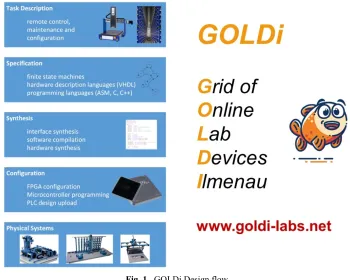
With our hybrid online lab GOLDi (Grid of Online Lab Devices Ilmenau), de-scribed in several papers [1]-[6], we support the design process of digital control sys-tems, which usually consists of the conceptual formulation and the design of the con-trol algorithm to finally achieve a validated concon-trol (see Fig. 1).
For the functional description, we offer different specification techniques by using non-commercial development tools for various web-based control units in the remote lab:
• a Finite State Machine (FSM) based design on the basis of digital automata -
exe-cuted within a client-side FSM interpreter
• a software-oriented design in C or assembler executed on microcontrollers
• a hardware-oriented design in hardware description languages or schematic block
Simulation and visual prototyping help to identify functional errors before starting practical work on real physical systems (the electro-mechanical models) in the lab room with one of the selected control units.
Fig. 1. GOLDi Design flow
While several professional or semi-professional design tools are available for soft-ware and hardsoft-ware oriented approaches, the FSM based design is only partially sup-ported. That’s why we enhanced the functionality of our GOLDi system by the GIFT (Graphical Interactive Finite State Machine Toolset) system which will be described in detail within this contribution. The GIFT system is an integral part of the GOLDi remote lab infrastructure. The first conceptual ideas for this GIFT system were pre-sented during REV2016 [7].
In the following, we will demonstrate how students can use the GIFT system to:
• specify the given task by using Finite State Machines
• simulate their design within the GIFT system to achieve a faultless solution and • export the generated next-state and output equations to the GOLDi remote lab
2
GIFT within the GOLDi Remote Lab Infrastructure
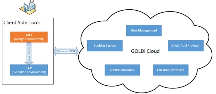
Based on the flexible grid structure of the GOLDi system an experiment consists of two components: on the one hand there are various control units (e.g. FSM, microcon-troller, FPGA). On the other hand, there are the electro-mechanical physical systems (e.g. elevator, 3-axis portal crane or warehouse models). A detailed description of the whole GOLDi architecture as well as different working modes can be found in [1]-[4]. As shown in Fig. 2, the GIFT system is part of the toolchain which is executed at client side within a web-browser. Any client side tools will be downloaded from the GOLDi cloud [12]. Two terms are used to classify the client side tools:
• Design Environment (GIFT, Atmel Studio, Quartus Prime) • Execution Environment (ECP- Experiment Control Panel).
Fig. 2. GIFT within the GOLDi- Architecture
2.1 Design Environment
The Design Environment is used to specify the user developed design by using a specification technique determined by the control unit. For FSM based designs, this Design Environment is the GIFT system which provides methods for:
• general FSM administration
• FSM input as automaton graph or transition table • handling of transition conditions and coding of states • simulation of single and parallel automata
• generation of the next-state (z) and output (y) equations • export of z/y equations to the ECP of the GOLDi system • generation equations for D and JK flip-flops.
Prime from Altera [9] in case of FPGA based control units for a more hardware-oriented design. The Design Environment is not limited to specification - it provides also support for syntax check of the design in the specification language as well as automatic tools for verification and validation. An important feature is also the possi-bility to generate output data (e.g. GIFT export data or Atmel *.hex, Altera *.pof binary files), which can finally be loaded into the Execution Environment.
2.2 Execution Environment
The Execution Environment is used to execute the user design within the GOLDi architecture. This is done by using the Experiment Control Panel (ECP). The ECP supports any of the available control units within the GOLDi architecture and is dy-namically configured on startup to fit the user’s choice in control unit/electro-mechanical physical system.
By using the ECP [7], students can:
• upload the synthesized/compiled designs to the corresponding control units (e.g.
microcontroller, FPGA) in the lab room
• import designs previously exported from the GIFT and execute them in the ECP’s
integrated FSM interpreter
• . watch the experiment by manipulating environmental variables inside an I/O
monitor (Fig. 3 shows an example to monitor the sensor signals of the 3-axis por-tal) or by observing the control of the physical system directly via a webcam
• handle the experiment (e.g. start, stop, reset)
• use the interactive debugging features (break on sensor/actuator changes or special conditions)
• single step processing, by pausing the execution on every sensor/actuator change • change environmental variables if necessary
• choose an individual initial situation for the experiment by manipulating the physi-cal system via mouse or keypad or by choosing a pre-defined initial state.
3
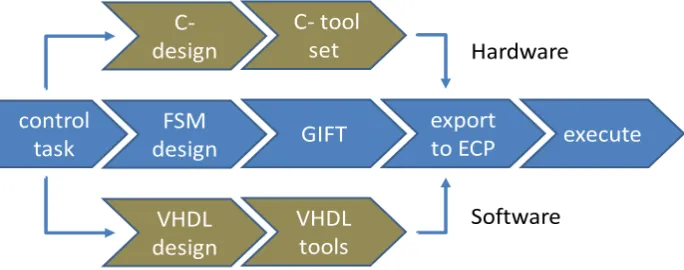
FSM Based GOLDi Design Flow
By using Finite State Machines as specification technique to realize various control tasks, the graphical interactive FSM toolset GIFT can be used directly within the GOLDi design flow (see 0).
Fig. 4. GIFT integrated GOLDi design process
3.1 Control Task Example
As an example, to introduce Finite State Machines to students in the first semester, we will discuss a design task by using the electro-mechanical model “3-axis portal crane” from the GOLDi remote lab infrastructure:
“On one spindle of a 3-axis portal crane, a tool carriage can be moved to the right and to the left. Limit switches provide input information on the left end position (xl) as well as the right end position (xr) of the tool carriage (xr, xl).
The motion can be controlled via the output variables (yl, yr) between • motion to the left (yl= 1, yr= 0),
An additional input variable xs signalizes • stop motion (xs = 0) or
• movement (xs = 1) to the left or right.
After a possible break, the movement in the original direction should be continued.”
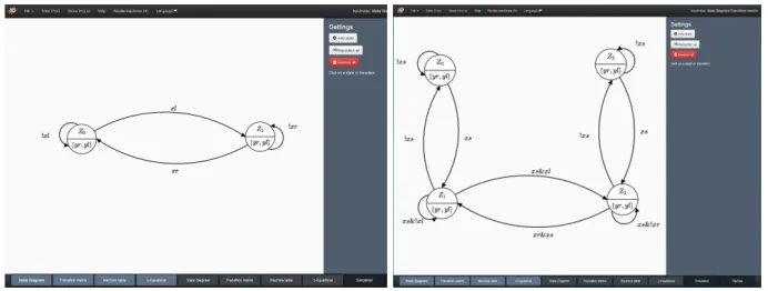
Fig. 5. Mealy (left) and Moore automata (right) for the spindle control task
3.2 GIFT FSM Design
In the following we demonstrate how students can specify their design based upon the given task by using Finite State Machines, simulate their design within the GIFT system to achieve a faultless solution step by step and can finally export the generated next-state and output equations to the ECP within the GOLDi remote lab infrastruc-ture.
Design of the Automaton Graph Such kinds of tasks are solved by developing a formal description of the control algorithm on the basis of an automaton graph and the corresponding Boolean equations. Fig. 5 shows two possibilities of corresponding automaton graphs by using the graph editor of the GIFT system:
• a Mealy automaton graph with two states as well as • a Moore automaton graph with four states.
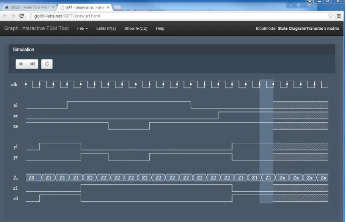
Simulation of the Design The student can proceed to the simulation process using graphical controls. That leads to appropriate state transitions caused by the changed set of input variables. Via waveform simulation (see Fig. 6) the temporal sequence of input and output variables and the internal state variables (coding the states) of partial automata can be shown.
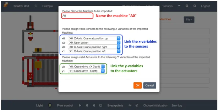
3.3 Export to ECP
Because the design is typically made with user-defined variables (e.g. xl, yr) the
student must adapt them to the real sensor and actuator interface notations (e.g. xr
must be replaced by x00 of the 3-Axis Portal sensor signals, which means “X-Axis:
Crane position right”). This can be done interactively for each input and output varia-ble within the ECP (see Fig. 8).
3.4 Design Execution
After uploading the next-state and output functions from GIFT or inserting these equations manually to the ECP, students are able to start the lab procedure and watch the behavior of their implemented design (see Fig. 3).
Fig. 6. Simulation tool of the GIFT system
Fig. 8. ECP: GIFT import functionality
In this case, the electro-mechanical model will be controlled via the Internet “from a distance” through the interpreter, running inside the student’s client PC. No addi-tional control units in the remote lab are necessary. In this case, only the input and output signals between the virtual control and the physical system are transferred via Internet.
In case of a selected virtual physical system the real physical system is represented by a simulation component within the ECP running on the client machine. No Internet connectivity to the laboratory and the physical systems in the remote lab is necessary for this kind of experiment. This mode is especially suitable for face-to-face lectures in a classroom where each student can work with the same virtual physical system simultaneously as well as in situations in which a stable network connection cannot be guaranteed (e.g. during travel or while using mobile networks).
4
Further Applications of the GIFT System
In this chapter, further applications of the GIFT tool beside the standard GOLDi development process mentioned above will be explained. These applications are used alongside our teaching models at Ilmenau University of Technology and have been proven to be successful in teaching in depth knowledge of techniques to achieve flaw-less designs based of Finite State Machines.
4.1 Teaching by Demonstration
system can demonstrate the resulting faulty behavior of the design task and gives information how to avoid them.
Due to the intuitive approach for the design of automata graphs it could be possible that students
• forget to specify all next-state conditions which lead to an incomplete design or • specify inconsistent next-state conditions which lead to a contradictory design.
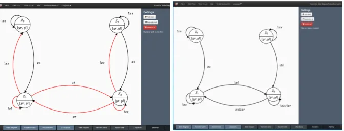
In both cases it is not recommended to realize such faulty designs because the be-havior of the implemented design is normally completely different as the desired behavior. Fig. 9 (left) gives an example for a faulty Moore automaton of the spindle design task with contradictions in states Z1 and Z3. The GIFT system automatically
indicates an incorrect design by highlighting the faulty state transitions in red and calculates the behavior of the resulting design based on the faulty next-state functions (Fig. 9, right). The correct Moore automaton graph is shown in Fig. 5, right.
Fig. 9. GIFT: Incorrect FSM design (left) and resulting automaton graph (right) for the given
spindle control task
The idea is to stop the motion during the “motion to left” (state Z1) or “motion to
right” (state Z3) to switch to the two “stop” states Z0 or Z2 by deactivating the xs
vari-able. The motion to left or right will be continued by activating xs again. Due to the
intuitive design, students often ignore, that it is only possible to change the motion direction (between Z1 and Z3 or vice versa) or stay in these states when xs is activated.
This will otherwise result in the mentioned contradictions. Although the resulting design can be activated to drive to the left or right direction from the two “stop” states Z0 or Z2 it is never possible to stop the motion again (see Fig. 9, below). In the worst
case the motion will not be stopped in Z3 if xs is deactivated and the right end position
is reached – which finally could damage the electro-mechanical model (or the hard-ware model in the f2f laboratory without any further protection mechanisms).
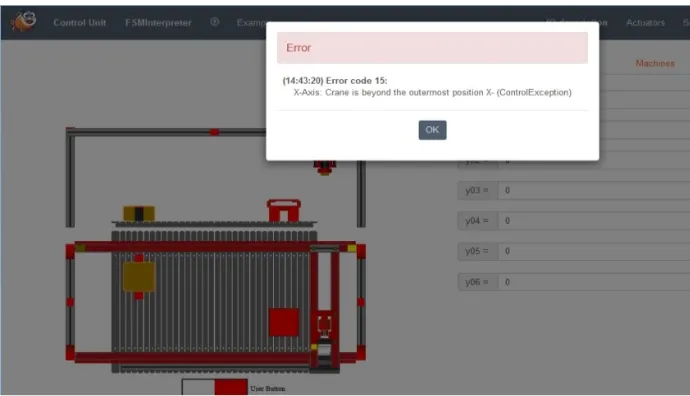
Fig. 10.ECP: Termination of the design execution due to design errors
4.2 GIFT as Interactive Training System
Complementing the theoretical knowledge taught during lectures, students can use the GIFT system as an interactive training system to deepen their knowledge in speci-fication techniques or for exam preparation. For that, students will get predefined automata designs:
• to derive the next-state and output functions and
• to check the given automaton regarding completeness and contradictions
• and can compare their solutions with the calculations of the GIFT system.
4.3 Preparation for Hands-on Lab Sessions
In preparation of the hands-on laboratories students can enter and simulate their FSM design for the given lab task. The GIFT assisted preparation process for hands-on lab sessihands-ons is shown in Fig. 11. In chands-ontrast to the automated GIFT integratihands-on into the GOLDi infrastructure and the execution of the design in the ECP, for hands-on lab sessions the students must realize their design by manually connecting integrated circuits (e.g. AND/NAND, OR/NOR Gates, D/JK flip- flops) by wires.
Fig. 11. GIFT assisted preparation for hands-on lab sessions
!"#$%"&'()*+' ,-.('./0'12*34#' 567"%$''.&378.&"7' 59:);"#*'
<)%=>)%2'
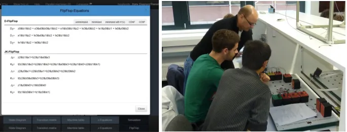
Equations for D and JK flip-flops (Fig. 12) as well as output equations can be gen-erated by the GIFT system. During the hands-on laboratory students will build up a sequential circuit on the basis of these next-state and output functions to control sim-ple technical facilities. While the results achieved within the GOLDi infrastructure are self-assessed, in hands-on lab sessions this is done by a teacher/tutor (Fig. 12).
Fig. 12. GIFT: Export of minimized D Flip-Flop and JK Flip-Flop equations (left),
used in hands-on lab session (right)
4.4 Design of Parallel Automata
Beside the design of single automata, students can use the GIFT system to design parallel automata. In principle, there are two possibilities:
• the automatic decomposition of a single automaton in several parallel automata or • the intuitive design of a set of single automata which will be interact finally as a
parallel system.
Automatic Decomposition of a Single Automaton into Parallel Automata This mode will be used mainly for teaching purposes to demonstrate different aspects for the design of parallel automata. Based on the design of a single automaton, students can choose the number of parallel automata and the state coding of the parallel au-tomata. Fig. 13 gives an example for a single automaton for a water level control task. Although GIFT detects contradictions in two states (Z2 and Z3, marked in red), it is
possible to use this design because these contradictions are part of the “don’t care”- conditions of the water level system.
The water level control task (see visual model in Fig. 13) in detail:
The number of active pumps as well as the alternation is described in the specifica-tion scheme (Fig. 13, right).
One example for decomposition into two parallel automata is shown in Fig. 14 and Fig. 15. The first parallel automaton (Fig. 14) is responsible for the number of active pumps:
• Z0: both pumps are inactive
• Z1: one pump is active – depending the actual state of the second parallel
automa-ton
• Z2: both pumps are active
Fig. 13.GIFT: Automaton graph for the water level control task (left) and the specification
scheme (right)
The second parallel automaton (Fig. 15) is responsible to switch between the two pumps for an alternative use if only one pump is active according to the specification scheme, shown in Fig. 13.
This approach of decomposition is often used in lectures and seminars to discuss special aspects with the students on the fly. To use the ECP execution for a number of students it is necessary to switch to the “virtual mode” – shown in Fig. 16
Intuitive Design of Parallel Automata In special courses the design of complex digital control systems will be taught to students of the 8th semester in form of a so called “project class”. The students have to solve a complex design task and document all the steps of their work in great detail. During the development process, a collection of design variants will be created; serving as case studies and provided via the Inter-net. Examples for such design tasks are amongst others controls for technical facilities like elevators, production cells and high storage warehouse systems. Solutions of such controls are available e.g. as a set of parallel automata (designed with the GIFT sys-tem) within the GOLDi remote lab infrastructure. Fig. 17 gives an impression of the execution of a control task for the Production Cell – realized with 12 parallel automa-ta.
Fig. 16. ECP: Execution of parallel water level control design in virtual mode
Fig. 17. ECP: Execution of a control task for the “Production Cell” with 12 parallel automata
5
Conclusion
own experiences. For all students, hands-on experiences are important to deepen their knowledge about topics they learned during lectures. Therefore they can use the de-scribed GIFT system to generate D or JK flip-flop equations to realize their schemat-ics in the hands-on laboratory.
One of the great advantages of the remote laboratory concept to our highly-motivated students is the possibility to test their theoretical knowledge in a real life environment at any time, allowing them to manage their daily schedule more individ-ually and efficient. The GIFT system offers the possibility to export the generated next-state and output equations directly to the Experimental Control Panel of the GOLDi remote lab system, and therefore is an integral part of the GOLDi remote lab architecture as well as the students’ learning process. With this possibility to execute their design tasks within our GOLDi infrastructure, we want to offer the students a working environment that is as close as possible to a real world laboratory. Under real laboratory conditions disturbances can appear and lead to failures of the control algo-rithm that cannot be detected under virtual lab conditions.
6
Acknowledgment
The authors would like to acknowledge the work of Tobias Vietzke, Andrey Yelmanov, Lisa-Marie Schilling, Nicole Ponischil, Lennart Planz, Stephen Ahmad, Bastian Hellweg, Felix Seidel, and David Sukiennik for their work within the GIFT- and GOLDi- framework.
This work was supported in part by the European Commission within the program “Tempus”, “ICo-op – Industrial Cooperation and Creative Engineering Education based on Remote Engineering and Virtual Instrumentation”, Grant No. 530278-TEMPUS-1-2012-1-DE-TEMPUS-JPHES [10] as well as “DesIRE - Development of Embedded System Courses with implementation of Innovative Virtual approaches for integration of Research, Education and Production in UA, GE, AM”, Grant No. 544091-TEMPUS-1-2013-1-BE-TEMPUS-JPCR [11].
We acknowledge support for the Article Processing Charge by the German Re-search Foundation and the Open Access Publication Fund of the Technische Universi-tät Ilmenau.
7
References
[1]M. Poliakov, H.-D. Wuttke, T. Larionova, K. Henke: “Automated testing physical models in remote laboratories by control event streams,” in Proc. 2016 Int. Conf. Interactive Mo-bile Communication, Technologies and Learning, San Diego, CA, USA, October. https://doi.org/10.1109/IMCTL.2016.7753764
[3]K. Henke, T. Vietzke, H.-D. Wuttke, S. Ostendorff, “GOLDi – Grid of Online Lab Devic-es Ilmenau,” Demonstration of Online Experimentation, exp.at’15 Int. Conf. , São Miguel Island, Azores, Portugal, Jun. 2015.
[4]K. Henke, H.-D. Wuttke, T. Vietzke, S. Ostendorff, “Using Interactive Hybrid Online Labs for Rapid Prototyping of Digital Systems,” Int. J. of Online Eng. (iJOE), vol. 6, pp. 57-62, Vienna, Oct. 2014.
[5]K. Henke, S. Ostendorff, H.-D. Wuttke, T. Vietzke, C. Lutze, “Fields of Applications for Hybrid Online Labs,” Int. J. of Online Eng. (iJOE), vol. 9; pp. 20–30, Vienna, May 2013. [6]K. Henke, S. Ostendorff, S. Vogel, H.-D. Wuttke, “A Grid Concept for Reliable, Flexible
and Robust Remote Engineering Laboratories,” Int. J. Online Eng. (iJOE), vol. 8, pp. 42– 49, Vienna, Dec. 2012.
[7]K. Henke, T. Vietzke, R. Hutschenreuter, H.- D. Wuttke: “The Remote Lab Cloud “goldi-labs.net”,” 13th Int. Conf. on Remote Eng. and Virtual Instrumentation REV 2016, Madrid, Feb. 2016. https://doi.org/10.1109/REV.2016.7444437
[8]Atmel Corporation: http://www.atmel.com [9]Altera Corporation: http://www.altera.com [10]ICo-op project Website: http://www.ICo-op.eu
[11]DesIRE project Website: http://tempus-desire.thomasmore.be [12]GOLDi-labs cloud Website: http://goldi-labs.net
8
Authors
Karsten Henke (corresponding author) is a scientist and lecturer at the Tech-nische Universität Ilmenau, Department of Computer Science & Automation, Ehren-bergstraße 29, 98693 Ilmenau, Germany. He obtained his PhD at the TU Ilmenau in 1986.
Tobias Fäth is a scientist and lecturer at the Technische Universität Ilmenau, De-partment of Computer Science & Automation, Ehrenbergstraße 29, 98693 Ilmenau, Germany. He obtained his Master of Science at the TU Ilmenau in 2016.
René Hutschenreuter is a scientist and lecturer at the Technische Universität Il-menau, Department of Computer Science & Automation, Ehrenbergstraße 29, 98693 Ilmenau, Germany. He obtained his Diploma in computer science at the TU Ilmenau in 2015.
Heinz-Dietrich Wuttke is a senior researcher and lecturer at the Technische Uni-versität Ilmenau, Department of Computer Science & Automation, Ehrenberg- straße 29, 98693 Ilmenau, Germany. He obtained his PhD at the TU Ilmenau in 1983.