1
Engineering Of Civil And Mechanical Structural Systems
Adaptive Brake By Wire
From Human Factors to Adaptive Implementation
Thesis Tutor
Prof. Mauro Da Lio
Doctoral Candidate
Andrea Spadoni
3
Table of contents
TABLE OF CONTENTS ... 3
LIST OF FIGURES ... 6
LIST OF TABLES ... 8
GENERAL OVERVIEW ... 9
INTRODUCTION ... 12
1. BRAKING PROCESS FROM THE HUMAN FACTORS POINT OF VIEW ... 15
THE BRAKING PROCESS AND THE USER-RELATED ASPECTS ... 15
1.1. BRAKE ACTUATOR AS USER INTERFACE ... 16
1.2. BRAKE FORCE ACTUATION: GENERAL MOVEMENT-FORCE DESCRIPTION ... 17
1.3. 2. BRAKE PEDAL FEELING AND IMPACT FACTORS ... 21
INTRODUCTION ON BRAKE FEELING ... 21
2.1. IMPACT FACTORS ON BRAKE FEELING... 21
2.2. RESEARCH PERFORMED BY RENAULT ABOUT FACTORS IMPACTING ON BRAKE FEELING ... 24
2.3. 3. PEDAL FEELING DESIGN ... 27
HIGH-LEVEL REQUIREMENTS ... 27
3.1. GENERAL ASPECTS ... 29
3.2. DESIGNING EXAMPLE... 30
3.3. SITUATION ADAPTED PROPERTIES -USE CASES AND USERS' EXPECTATIONS ... 34
3.4. SITUATION RECOGNITION CRITERIA... 37
3.5. 3.5.1. Adaptation braking speed reduction while driving or to stop ... 37
3.5.2. Target and parking braking... 38
3.5.3. Emergency braking ... 38
3.5.4. Constant speed braking (e.g. downhill) ... 38
3.5.5. Repeated hard braking - Similar to emergency braking (e.g. race scenario) ... 38
3.5.6. Fading effect - Holding the vehicle and hard repeated braking actions ... 38
3.5.7. Stopping in vehicle manoeuvre... 39
3.5.8. Holding the stopped vehicle for restarting on plane road ... 39
3.5.9. Holding the vehicle and adapt its position on a slope ... 39
3.5.10. Holding the vehicle stopped for restarting on a slope ... 39
3.5.11. Stop the vehicle and key off - Parking service brake... 39
3.5.12. On highway, not perform speed reduction but foot touch the brake pedal ... 39
3.5.13. Full loaded vehicle... 40
SCENARIO –USE CASES DESCRIPTION ... 40
3.6. 4. PEDAL FEELING CURVES ... 43
ADAPT CURVE ... 44
4.1. LOW/PARKING CURVE ... 45
4.2. EMERGENCY CURVE ... 46
4.3. CONSTANT CURVE ... 47
4.4. 5. LOGICAL ARCHITECTURE AND IMPLEMENTATION ... 49
4
MATLAB/STATEFLOW DIAGRAM ... 50
5.2. 5.2.1. Macro State ... 50
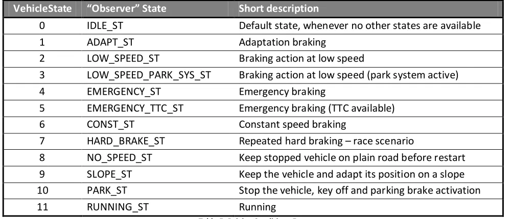
5.2.2. Observer Module ... 52
5.2.3. States enter conditions within “Observer” module ... 52
5.2.4. State Action/Output... 54
5.2.5. AccCalc Module ... 54
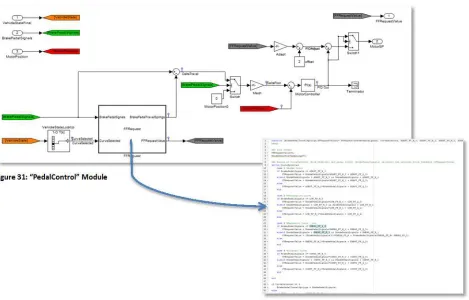
5.2.6. “PedalControl” Module ... 55
MODEL SIMULATION &DEPLOY ... 57
5.3. 5.3.1. Model Simulation... 57
5.3.2. DSPACE MicroAutoBox HW ... 57
5.3.3. Model Deploy on DSPACE ... 58
6. MODEL VALIDATION THROUGH EXPERIMENTAL VEHICLE DATA ... 61
VEHICLE INTEGRATION ... 61
6.1. TRIALS DATA ... 63
6.2. 6.2.1. Adaptation braking ... 63
6.2.2. Running ... 63
6.2.3. Braking action at low speed - Park/Stop ... 64
6.2.4. Emergency braking ... 65
6.2.5. Constant speed braking ... 65
6.2.6. Repeated hard braking ... 66
6.2.7. Keep the stopped vehicle on plain road before restart ... 66
6.2.8. Keep the vehicle and adapt its position on a slope ... 66
6.2.9. Stop the vehicle, key off and parking brake activation ... 67
6.2.10. Mixed Scenario ... 67
BENCH PREPARATION ... 68
6.3. VALIDATION RESULTS ON “OBSERVER” MODULE ... 68
6.4. 6.4.1. Repetition of all the tests ... 70
VALIDATION RESULTS “ACCCALC” AND “PEDALCONTROL” MODULE ... 70
6.5. 7. TESTS ON CLOSED-LOOP MOTOR CONTROLLER ... 71
ECMOTOR ... 71
7.1. MOTOR CONTROL TEST ENVIRONMENT ... 71
7.2. STEPINPUT ... 72
7.3. RAMPINPUT ... 73
7.4. STAIRINPUT ... 74
7.5. SINEINPUT ... 75
7.6. RESULTS ... 76
7.7. 8. CONCLUSIONS ... 77
9. NEXT STEPS ... 81
DRIVING SIMULATOR TEST &EXPERIMENTAL PLAN ... 81
9.1. 10. ANNEX 1: THE DESIGN OF BRAKE PEDALS - MATERIALS AND RATIO... 83
11. ANNEX 2: BRAKE BY WIRE PEDAL DESIGN HYPOTHESES AND REVIEW OF PATENTED TECHNOLOGIES ... 87
GENERAL REMARKS ... 87
11.1. REVIEW OF RELEVANT PATENTS... 89
5
11.3.1. Linear sensor, spring and rubber design solution ... 92
11.3.2. Rotating motor-driven solution ... 95
11.3.3. Magneto-rheological brake design ... 96
11.3.4. Other design solution ... 97
12. ANNEX 3: BRAKE BY WIRE PEDAL REACTION TIMES AND BRAKING BEHAVIOR: EXAMPLE FROM AN EXPERIMENTAL RESEARCHES ... 101
12.1.1. Relevant research studies about braking forces and deceleration ... 104
EMERGENCY REACTION AND ACTUATION TIMES... 107
6
List of figures
FIGURE 1:RESEARCH WORKFLOW ... 13
FIGURE 2:CONTROL LOOP DRIVER-VEHICLE DURING BRAKING PROCESS (BREUER ,BILL,2008)... 15
FIGURE 3:TIME PHASES OF AN EMERGENCY BRAKE ACTION (BREUER ,BILL,2008) ... 16
FIGURE 4:EXAMPLE OF NORMAL BRAKING PHASES (KASSAGI,2003) ... 16
FIGURE 5:BRAKING SYSTEM HMIINPUT-OUTPUT ... 17
FIGURE 6:PEDAL AND DECELERATION CHARACTERISTICS (BRAUER ,BILL,2008) ... 18
FIGURE 7:EXAMPLE OF PEDAL FORCE AND PEDAL TRAVEL DESCRIBED BY TYPE OF VEHICLE (BREMBO 2012) ... 19
FIGURE 8:REGIONS OF THE USUAL BRAKE PEDAL CHARACTERISTIC (BILL ET AL.,1999) ... 21
FIGURE 9:BRAKE PRESSURE,FORCE,JUMP-IN AND PEDAL TRAVEL ... 24
FIGURE 10:PARAMETERS IDENTIFIED BY RENAULT TO ADJUST BRAKE FEELING LAWS (DAIROU,2003). ... 25
FIGURE 11:CORRELATION AMONG PREDICTED SENSATION AND SENSORY RATINGS (RENAULT,DAIROU,2003) ... 26
FIGURE 12:EXAMPLE OF BRAKE BY WIRE ARCHITECTURE (CHEON ET AL.,2010)... 29
FIGURE 13:EXAMPLE OF FUNCTION-ANALYSIS-SYSTEM-TECHNIQUE DIAGRAM FOR BRAKE DESIGN (PAN,2007) .... 30
FIGURE 14:EXAMPLE OF QUALITY-FUNCTION-DEPLOYMENT DIAGRAM FOR BRAKE DESIGN (PAN,2007)... 31
FIGURE 15:DERIVED CURVES BY JUMP-IN VARIATION 0%,5%,10%(BILL ET AL.,1999). ... 33
FIGURE 16:DERIVED CURVES BY IDLE PEDAL TRAVEL VARIATION 10MM,20MM,30MM (BILL ET AL.,1999). ... 33
FIGURE 17:ACTIVE BRAKE PEDAL BEHAVIOUR STRATEGY OUTLINE ... 34
FIGURE 18:DRIVING USE CASES CONCERNING BRAKING ... 35
FIGURE 19:DESIRED SITUATION-ADAPTED PROPERTIES OF THE ACTUATION DEVICE (BILL ET AL.,1999) ... 35
FIGURE 20:HYPOTHESES OF SITUATION-ADAPTED BRAKING CURVES ACCORDING TO USERS'EXPECTATIONS ... 37
FIGURE 21:ADAPT CURVE -FORCE VS PEDAL TRAVEL AND ACCELERATION VS PEDAL TRAVEL ... 44
FIGURE 22:LOW/PARKING CURVE -FORCE VS PEDAL TRAVEL AND ACCELERATION VS PEDAL TRAVEL... 45
FIGURE 23:EMERGENCY CURVE -FORCE VS PEDAL TRAVEL AND ACCELERATION VS PEDAL TRAVEL ... 46
FIGURE 24:CONSTANT CURVE -FORCE VS PEDAL TRAVEL AND ACCELERATION VS PEDAL TRAVEL ... 47
FIGURE 25:SWARCHITECTURE ... 49
FIGURE 26:MODEL MAIN STRUCTURE ... 50
FIGURE 27:MODEL:INIT STATE MACHINE AND CONTROL BLOCK ... 51
FIGURE 28:“OBSERVER”,“PEDALCONTROL”,“ACCCALC” ... 51
FIGURE 29:"OBSERVER"MODULE ... 52
FIGURE 30:“ACCCALC” MODULE ... 54
FIGURE 31:“PEDALCONTROL”MODULE ... 56
FIGURE 32:PID SETTING ... 57
FIGURE 33:DSPACEMICROAUTOBOX HW ... 57
FIGURE 34:SIMULINK®LIBRARY WITH DSPACE COMPONENTS ... 58
FIGURE 35:DSPACECONTROL PANEL ... 59
FIGURE 36:HWINTEGRATION VIA OBD... 61
FIGURE 37:DATA COLLECTION VIA SMARTPHONE &SMARTPHONE AXIS ... 62
FIGURE 38:ADAPTATION BRAKING ... 63
FIGURE 39:RUNNING ... 64
FIGURE 40:BRAKING ACTION AT LOW SPEED ... 64
7
FIGURE 42: CONSTANT SPEED BRAKING DATA COLLECTED ... 65
FIGURE 43:PLAIN ROAD AND RESTART ... 66
FIGURE 44:KEEP THE VEHICLE AND ADAPT ITS POSITION ON ASLOPE... 67
FIGURE 45:MIXED SCENARIO ... 67
FIGURE 46:LOG REPLAY CHAIN... 68
FIGURE 47:EC MOTOR AND ENCODER ... 71
FIGURE 48:MOTOR CONTROL BY PIDCONTROLLER ... 71
FIGURE 49:MOTOR POSITION (MAGENTA)VS STEP INPUT (YELLOW) ... 72
FIGURE 50:MOTOR POSITION (MAGENTA)VS STEP INPUT (YELLOW)-ZOOM-IN ... 72
FIGURE 51:MOTOR POSITION (MAGENTA)VS RAMP INPUT (YELLOW) ... 73
FIGURE 52:MOTOR POSITION (MAGENTA)VS RAMP INPUT (YELLOW)-ZOOM-IN... 73
FIGURE 53:POSITION (MAGENTA)VS STAIR INPUT (YELLOW)... 74
FIGURE 54:MOTOR POSITION (MAGENTA)VS STAIR INPUT (YELLOW)-ZOOM-IN ... 74
FIGURE 55:MOTOR POSITION (MAGENTA)VS SINE INPUT (YELLOW) ... 75
FIGURE 56:MOTOR POSITION (MAGENTA)VS SINE INPUT (YELLOW) -ZOOM-IN ... 75
FIGURE 57:DRIVING SIMULATOR ... 81
FIGURE 58:TRADITIONAL BRAKE PEDAL FORCE OUTLINE ... 84
FIGURE 59:CALCULATION OF THE PEDAL RATIO ... 84
FIGURE 60:INSTANTANEOUS RATIO VS PEDAL TRAVEL FOR A FIXED RATIO PEDAL (MOK,2007). ... 85
FIGURE 61:3D MODEL AND FINAL ASSEMBLY OF VARIABLE RATIO CONCEPT BRAKE PEDAL (MOK,2007) ... 86
FIGURE 62:EXAMPLE OF MORPHOLOGICAL CHART FOR BRAKE-BY-WIRE PEDAL DESIGN (PAN,2007) ... 88
FIGURE 63:EXAMPLE OF PUGH TABLE FOR BRAKE-BY-WIRE TECHNOLOGY EVALUATION (PAN,2007)... 89
FIGURE 64:RELEVANT PATENT TIMELINE... 91
FIGURE 65:PEDAL SIMULATOR : BRAKE FEEL TUNING BY SOFTWARE (CHEON ET AL.,2010) ... 92
FIGURE 66:PEDAL SIMULATOR DESIGN - RUBBER TYPES AND EFFORT (CHEON ET AL.,2010) ... 93
FIGURE 67:EXAMPLE OF SOFTWARE DESIGN ARCHITECTURE (CHEON ET AL.,2010) ... 93
FIGURE 68:SPRINGS/RUBBER FEELING SIMULATOR CONCEPT (CONTINENTAL PATENT US20060071545) ... 94
FIGURE 69:TTTTECHAND DELPHI CONCEPT FOR BRAKING PEDAL MODULE ... 94
FIGURE 70:MOUNT SENSOR TO PEDAL AND BACK BRACKET WITH A FOUR-BAR LINKAGE (PAN,2007). ... 95
FIGURE 71:LINEAR SENSOR BRAKE BY WIRE PEDAL CONCEPT (PAN,2007). ... 95
FIGURE 72:MOTOR DRIVEN FORCE FEEDBACK IN HAPTIC ACCELERATOR PEDAL (DE ROSARIO ET AL.,2010) ... 95
FIGURE 73:BRAKE PEDAL DRIVEN BY MOTOR (STACHOWSKY ET AL.PATENT US20030122418) ... 96
FIGURE 74:MAGNETO-RHEOLOGICAL BRAKE PEDAL FEEL EMULATOR (DELPHI PATENT US20020108463) ... 96
FIGURE 75:BASIC CONFIGURATION OF A MAGNETO-RHEOLOGICAL BRAKE CONCEPT (PARK ET AL.,2006) ... 97
FIGURE 76:"NARUSE"PEDAL (NARUSE PATENT,US20110107870)... 97
FIGURE 77:PEDAL EFFORT PLOTTED AGAINST TIME DURING PANIC AND NORMAL BRAKING (FITCH ET AL.,2010B) ... 103
FIGURE 78:CUT-OFF PFG VALUES FOR SATISFACTORY DRIVER-VEHICLE BRAKING PERFORMANCE (DOT,1970).... 105
FIGURE 79:RECOMMENDED DECELERATION/PEDAL FORCE SPACE (DOT,1970) ... 105
8
List of tables
TABLE 1:DETAILED VARIABLES INFLUENCING THE BRAKE PEDAL FEEL (BASED ON BILL ET AL,1999). ... 23
TABLE 2:BRAKE BY WIRE POTENTIAL BENEFITS ... 28
TABLE 3:FUTURE BRAKING REQUIREMENTS AND POSSIBLE BENEFITS (SOURCE:BREUER,BILL,2008) ... 28
TABLE 4:EXAMPLE OF PEDAL DESIGN ENGINEERING SPECIFICATION:ACTIVE PEDAL FEELING DESIGN PARAMETERS... 32
TABLE 5:DRIVING CONDITIONS ENUM ... 54
TABLE 6:MAPPING VEHICLE STATE -CURVE SELECTED ... 55
TABLE 7:VALIDATION RESULTS ON "OBSERVER" ... 69
TABLE 8:SIMULATOR TESTS EXPERIMENTAL PLAN ... 81
TABLE 9:LIST OF RELEVANT PATENTS ABOUT BRAKE BY WIRE TECHNOLOGY ... 89
TABLE 10:REVIEW OF EMERGING BRAKE TECHNOLOGIES (WINKLER,2005). ... 98
TABLE 11:DRIVERS' BRAKING PERFORMANCE AT THE SURPRISE CONDITION (FITCH ET AL.,2010A) ... 101
TABLE 12:DRIVERS' BRAKING PERFORMANCE AT THE EXPECTED CONDITION (FITCH ET AL.,2010A) ... 102
TABLE 13:DRIVERS' BRAKING PERFORMANCE TO AN EXPECTED AUDITORY ALARM (FITCH ET AL.,2010A) ... 102
TABLE 14:EXAMPLE OF APPLIED BRAKING FORCE IN COACHES AT GRADUAL LEVELS (GRSG-91,2006)... 104
9
General overview
Brake systems are undergoing radical change. Decisions to apply (or release) brakes are being made automatically by computer-controlled systems (e.g., ABS and ACC). The type, complexity and shear number of such automatic systems is growing. To enabled automatic control, electro-hydraulic valves acting under computer control have been introduced to the traditional electro-hydraulic systems. Electro-hydraulic brake-by-wire has been introduced, and in the foreseeable future, the brake application system is likely to become predominately electro-mechanical, largely doing away with hydraulic components (NHTSA, 2005).
In recent years, the friction brake and the hydraulic actuation system have remained overwhelmingly dominant, but computer-controller “intelligent” systems and are being given increasingly important (and numerous) roles in deciding how and even when to apply brakes. This trend will continue and may lead to the demise of the traditional hydraulic system in favour of the so-called brake-by-wire systems: systems using electrohydraulic actuation and, eventually, electro-mechanical actuation. Recently, regenerative brakes have appeared in small numbers (in hybrid and fully electric vehicles) to supplement the friction brake. The trend is likely to continue, albeit slowly. There may be some very long-term potential for reversal of these roles, i.e., motors acting as regenerative brakes supplying the primary braking effort with smaller friction brakes playing a supporting role. Computer-controlled brake application has become commonplace. Some of these systems modify braking initiated by the driver. Anti-lock braking systems (ABS) and traction control systems apply (or release) hydraulic pressure to prevent excessive (positive or negative) wheel slip. Brake-assist systems accelerate (in time), and may also raise the level of, brake application to improving emergency brake applications. Current brake-assist systems do so by altering the behaviour of the vacuum booster when the driver applies the brake more rapidly than normal. Other automatic systems apply the brake(s) on their own (as apposed to modifying driver-initiated braking). Stability enhancement systems apply individual wheel brakes to prevent pending yaw instability or can apply brakes generally to lower speed for the purpose of avoiding excessive lateral acceleration and, hence, rollover. More recent versions of Adaptive Cruise-Control (i.e. ACC) systems apply service brakes to adjust speed and maintain headway relative to a leading vehicle. The future is likely to see expanded use of similar automatic brake application in the forms of various crash mitigation and crash-avoidance systems.
Traditionally, the primary control interface between the driver and the brake system has been the brake pedal: a mechanical link through which the driver energizes the hydraulic master cylinder with forces applied by the foot. A secondary control interface is the parking-brake actuator, usually a hand operated lever or another foot pedal. Dash mounted warning lights provide an interface by which the driver can monitor the health of the brake system and its auxiliary elements. Finally, the rear-mounted brake lights constitute and advisory interface with other drivers regarding braking activity of the host vehicle.
10
also provide a distinctly different pedal feel when the system is activated as compared to pedal feel during normal applications.
The introduction of brake-by-wire systems has the potential for major changes to the primary driver/system interface. In theory, brake-by-wire does not require any forceful actuation by the driver, thereby eliminating the basic reason for actuation via a foot pedal. While the primary actuator could certainly remain as a pedal with either a displacement or pedal-force transducer, it could just as well be a hand-operated lever (joystick) or button as has been demonstrated in some experimental systems. On the other hand, in the foreseeable future, it is apparent that manufacturers have no plans to launch such changes. Indeed, the greater concern seems to be the desire to maintain a traditional pedal feel as brake-by-wire systems evolve. Moreover, manufactures will favour maintaining at least two-wheel hydraulic brake actuation as a fail-safe backup system for some time. Thus, the master cylinder is likely to remain for some time as part of a backup system.
The electro-mechanical form of brake-by-wire also offers obvious motivation for altering parking-brake application. In many cases the same electro-mechanical device used to apply the wheel brake for service braking would be appropriate for applying the brake in emergency or parking situations. (Separate electric parking brake applicators have already been developed). With electric application, all of the numerous mechanical components associated with parking brake application could seemingly be replaced with little more than an electric switch and some wiring, implying very attractive weight and cost savings.
If we assume that “the brake system” encompasses all of the automated systems that apply brakes, the monitoring interface between the driver and that brake system is becoming far more extensive and complex. The common “ABS” warning light was the first small step in this progression. This warning light provides a simple binary message regarding the general health of the system: either the ABS is properly operational or it is not. On the other hand, ACC systems, for example, have rather elaborate dash-board displays that not only indicate general system health, but provide continuing information on the current operating state on a moment-to-moment basis. These visual displays may indicate various driver-selected settings as well as monitoring system status (e.g., target vehicle recognized/not recognized). Additional visual displays and/or audible warnings indicate that the driver must take over the braking task. As they become available, forward-crash avoidance, lane-departure avoidance and other such systems will presumably have similarly elaborate performance-monitoring interfaces (NHTSA, 2005).
Finally, vehicle brake systems interface not only with the driver of the vehicle on which they are mounted, but also with the drivers of following vehicles. Previously, the decision as to when to turn on brake lights was rather straight forward: when the driver applied the brakes. The means to do so was similarly simple: with a switch activated by initial pedal motion or initial brake-pressure rise. Whether or not automatic brake application should be accompanied by brake-light actuation is not always so clear cut. The proliferation of automatic systems for applying brakes may raise this same question again in differing contexts. In any case, the means by which brake lights are actuated cannot remain so simple. Some set of brake actuations must result in brake lights turning on; others must be filtered out so that do not cause the brake lights to illuminate (NHTSA, 2005).
11
Hydraulic regenerative braking may be introduced soon. In the long term, regenerative braking could become the primary braking mechanism(NHTSA, 2005).
Experimental results from test user tests confirm the need of a driver dependant adaptive behaviour of the brake pedal characteristic and of a "smart" brake pedal for future brake-by-wire system. That could also fit theoretical considerations for the enhancement of active safety as significant improvement of the drivers condition during braking and an increase of the braking stability of the vehicle seem possible.
12
Introduction
The introduction of brake by wire system is replacing the traditional mechanical control systems with ECUs and active systems. This process is raising the need to reproduce feelings of eliminated static mechanical components (i.e. hydraulic fluids, pumps and cylinders). Thanks to electromechanical actuators and human-machine interfaces (i.e. active pedal) it is possible to reproduce such feelings and, therefore, be able to change their features.
This process makes possible customization of the pedal feelings depending on several factors (i.e. surrounding braking scenario, driver characteristics, race vs day-by-day driving condition). Since braking maneuvers are typically critical and, especially, involve the driver, the design and development of brake by wire system should start from human factors considerations in order to increase acceptance and braking effectiveness.
The objective of this research is to define methods and strategies for designing adaptable pedal brake feeling. The methods shown in the following chapters could be applicable in order to find different solutions basing on the requirements of the specific project. In fact, the strategies proposed in the research are not restricted to a certain project but they are potentially pliable to others environment, making the adaptive approach global. Driver acceptance and braking effectiveness could be highly improved by means of adaptive pedal feelings.
13
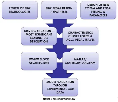
all the data are provided via standard CAN bus. One other important point is the presence or not of ADAS: in this case the vehicle is not equipped with ADAS. However, the implementation takes into consideration the availability (or not) of such systems, like automatic parking system and information on the time to collision. Figure 1 shows the workflow described so far.
15
1.
Braking process from the Human Factors
point of view
The braking process and the user-related aspects
1.1.
The basic demands in the brake system are the provision of an optimal responsiveness and decelerations behaviour in all driving and environmental conditions. Besides the objective measurable variables, the customer's subjective perception during the braking process is of particular importance when rating the quality of braking behaviour.
The layout aims at giving the customer's confidence in the safety level and the performance of their car in terms of positive distinct features. Brake pedal felling, responsiveness, and controllability are fundamentally important besides the basic performance and tracking stability during braking process.
The brake pedal represents the driver's central interface for controlling the braking process. Vehicle deceleration and pedal force characteristics are the important responses to the driver providing the subjective impression of responsiveness and controllability. The operating range starts from soft comfort braking to normal braking to standstill and full braking in dangerous situations.
The system technical presentation shows that the layout and optimization of the brake pedal feeling and thus the responsiveness require a detailed consideration of the overall brake system.
Figure 2: Control Loop Driver-Vehicle During Braking Process (Breuer , Bill, 2008)
After user perception and reaction, every braking action can be decomposed according to the following 5 phases:
- Accelerator release;
- Foot displacement from accelerator pedal to brake pedal; - Hit of the brake pedal (generally in the 100 to 200 first ms) ; - Regulation of applied braking force;
16
Figure 3: Time Phases Of An Emergency Brake Action (Breuer , Bill, 2008)
Figure 4: Example Of Normal Braking Phases (Kassagi, 2003)
Brake actuator
as user interface
1.2.
Taking into consideration the braking phases, the brake actuator is the main user interface the drivers use. Within normal vehicle, it is the responsible of both actions and feedbacks from/to the driver. Basically:
- Input:
- main brake actuator (e.g. pedal);
17 - Output:
- pedal brake feeling;
- user' perception of vehicle deceleration;
- brake rear vehicle lights (they warn other drivers about vehicle deceleration); - service brake instrument panel warning light;
- malfunctioning instrument panel warning lights (i.e. low fluid level, EBD failure, brake pad consumption, ABS failure);
- ADAS dashboard HMI (e.g. ACC, Hill Holder, etc.).
Figure 5: Braking System HMI Input-Output
Brake force actuation: general movement-force description
1.3.
The pedal characteristic and feeling the driver perceives during a braking process is given by the force on pedal travel characteristic.
For actuating the pedal a certain response force is required that is basically characterized by preload and friction within the system. During shorter pedal travels, no significant increase of the force can be noticed. This can be explained by the free travels within the system; alternatively, a deceleration is already caused after overriding the free travels without an increase of the force according to the layout. The results is also evident the presentation of the decelerations by pedal force. This function, which is also called the "springer functions" has a positive effect on the subjective perception of the responsiveness.
After this initial step, the pedal force is generated throughout the pedal travel and an incline of the curve can be noticed after the intervention of the Electronic Brake Force Distribution (EBD). At a certain value, the control point of the brake booster is reached and thus the maximum brake force support is reached. Beyond this point the driver perceived a mechanical stop. For this reason, a suitable dimensioning of the brake system guarantees that the control point does not have to be exceeded even in cases of full braking.
18
Figure 6: Pedal And Deceleration Characteristics (Brauer , Bill, 2008)
A number of design variables concerning braking response and controllability can be derived from all the characteristics presented above:
- length of travel and minimal braking pressure for certain pedal travel; - the initial step;
- response force;
- incline of pedal force development throughout pedal travel and deceleration.
A complex and high-precision optimization of all the parameters is necessary for attaining an actuating feeling the customer perceives as a particular quality feature. For instance even moderate increases of the response force can lead to the fact that the brake is subjectively perceived as being dull. Alternatively, it becomes evident that a short pedal travel is subjectively perceived as being favourable when the pedal forces are equal (Breuer , Bill, 2008). Brake force measurement and evaluation it is strictly related to type of car and its braking system. Applied forces and pedal travel could differ a lot between different type of cars and technologies involved in the braking system. The effectiveness of the force applied in traditional system is mainly dependent on the pedal ratio of the brake. The effective force in traditional brake systems with pedal lever and push-rod can be calculated using the following equation (Oshiro 2010):
Effective Force = Force Applied * Pedal Ratio
19
pedal of at least 10-15 kgs and the pressure on the pedal must be sustained until the vehicle has come to a complete stop (Harsha et al., 2008). Although it has been established that some 50% of car drivers do not depress the brake pedal hard enough in emergency braking situations (Youshida, 1998) and that the most subjects apply too little force to the brake pedal and fail to maintain constantly high pressure on it (Kinkner et al., 1997).
Inexperienced drivers tend in critical situation to relax pressure on the brake pedal between 0,1s and 0,2s after initiation of breaking and only start to reapply pressure when the hazard is dangerous close (Zomotor, 1987).
On the other hand, significant differences can be observed between touring cars and sport cars: touring cars have usually longer pedal travel (upper than 72 mm) and less required force (i.e. between 10 and 20 kgs) than sport cars. Typically sport cars require a large braking pressure (i.e. between 18 and 25 kgs) and the brake pedal has a very short travel (i.e. between 34 and 62 mm). In extreme cases, for instance in sigle-seater race vehicles, the brake pedal needed to take a about 2000 N force (about 204 kg), but needed to also be lightweight for design points. In such a cases, the pedal design is even more important, especially at the contact point from the foot of the driver, because that is where the most force would be applied (Scheitlin, 2011).
Figure 7: Example Of Pedal Force And Pedal Travel Described By Type Of Vehicle (Brembo 2012)
21
2.
Brake pedal feeling and impact factors
Introduction on brake feeling
2.1.
Brake pedal feeling is the physical sensation and perception experienced by the car drivers during braking actions. It is typically referred to the foot sensation touching and acting on the brake pedal following leg-foot movement. As braking is a mechanical process first involving vehicle deceleration, brake pedal feeling results in a complex and structured phenomenon and physical sensation experienced as long as pedal is actuated by driver. Thus brake pedal feeling is first of all strictly related to the applied force and the experienced pedal travel. Other mechanical, physical, dynamics and external situation related factors impact on the perceived brake pedal feeling.
Figure 8: Regions of the usual brake pedal characteristic (Bill et al., 1999)
Impact factors on brake feeling
2.2.
22
About vehicle braking systems, the crucial user interface is the brake pedal as it is both input and output interface. The pedal feel provides feedback to the driver about the performed braking manoeuvre and the state of the braking system. The pedal characteristics can be influenced by changes to the brake system and to the overall actuation complex. This variability is mainly exploited as part of style of the vehicle marque or model. The key parameters brake-related determine pedal feel can be listed as follow (Breuer, Bill, 2008):
- pedal response force; - pedal idle travel;
- braking two-stages effect (also called damping or jump-in factor); - braking boost (deceleration/pedal force);
- hysteresis; - pedal travel;
- pedal travel and pedal force at the run out point (ideally corresponds to maximum deceleration);
- increase in pedal travel and pedal force on fading; - response time;
- release time.
When braking, driver is integrated as a controller in the closed-loop control system within the vehicle control line. Following research hypothesis and driving experiments, the dependence of brake pedal parameters from braking situations has been shown. For instance, in modern vehicle electronically equipped, brake pedal interface becomes even more important in some situations (e.g. hard braking occurrences, ABS activations and pedal vibration).
If the positive subjective brake pedal feel has a positive influence on the operating reliability of the driver, performing of emergency braking and speed adapting braking are also influenced.
While brake pedal characteristic curves can be judged with the usual experimental means of vehicle engineering, the consideration of brake pedal feel requires also methods from ergonomic and human factor sciences.
23 Pedal and braking system related
aspects
Travel
Idle travel
Pedal transmission Clearance
System volume usage Increasing of travel on fading
Force
Pedal transmission Booster amplification Required applying force Pedal response force Increasing of force on fading
Damping (also called Jump-in) and hysteresis
Two-stages effect Component-friction Booster hysteresis Booster dynamics
Throttling if booster pneumatic ABS valve throttling
Line cross section
Vehicle deceleration Friction brake pad / disc Friction tire / street surface State of the vehicle Gradient of the street
Vehicle parameters Geometry and positions of pedal, seat, steering wheel Special vehicle behaviour
Vehicle challenge characteristic Vehicle type
Driver Body size
Condition and motivation Power and capacity Demands
Gender Driving style
Environment Weather
Street course
Road surface and type Traffic density
Table 1: Detailed variables influencing the brake pedal feel (based on Bill et al, 1999).
24
For instance, regarding emergency braking and dosed comfort braking, jump-in and idle travel are important parameters for controlling the braking system. The jump-in, as specific feature of pneumatic brake booster, is performed as a brake pressure jump at the end of the idle travel. With this pressure offset the clearance of can be surmounted and a defined small vehicle deceleration will be performed with very low brake pedal force, which gives the driver a positive feedback in brake pedal feel when starting to brake. With missing jump-in, the brake pedal is felt as "blunt" as vehicles without braking force enhancement (Bill et al., 1999).
Figure 9: Brake Pressure, Force, Jump-In And Pedal Travel
According to very relevant experimental tests performed by Bill et al. (1999) in order to investigate brake pedal under real road conditions in view of oncoming of brake by wire systems, the variations of individual brake pedal parameters seem to be difficult to recognize clearly for most drivers. For instance, the isolation of the force and travel information at the brake pedal in combination with retroactive vehicle deceleration is difficult to recognize especially for inexperienced drivers.
Some of the above listed parameters are impacting on the overall brake pedal feeling perceived by users and also on vehicle braking performance (i.e. braking distances) but they are not related to pedal design or to the braking system itself. Typically external factors as road type, weather conditions or maintenance aspects impact on performances. These aspect could be foreseen in use case definition but cannot be set as fixed conditions for technology development and future product on market. Thus it also important to consider them as relevant variables.
Information about the significance of the above parameters for braking distance is based on literature. The most relevant findings of those studies are cited below (Greibe, 2007).
Research performed by Renault about factors impacting on brake
2.3.
feeling
25
To sum up the research, Renault first defines "laws" pedal feeling is based on, both user action and physical related defining technical pedal characteristics.
Assuming that brake pedal feeling is strictly related to applied effort, pedal stroke (i.e. travel) and vehicle deceleration, Renault identified 11 primary factors that could be modified and set in order to adjust brake pedal feeling laws.
Figure 10: Parameters identified by Renault to adjust brake feeling laws (Dairou, 2003).
Detailed user tests have then been carried out by Renault in order to estimate how much each factor could impact on brake feeling and to define the driver model about perception. Through prototype equipped vehicle and pedal simulator, it was possible to test different braking configuration in order to assess the impact factor and the correlation between the 11 variables identified. In order to limit the test to most relevant characteristics and ensure controllability of variables, the Design of Experiment was defined involving a subset of 7 pedal attributes:
- travel; - idle travel; - effort;
- responsiveness;
- deceleration perceived;
- ease of balance (i.e. ease of modulation); - graduality of braking (i.e. controllability).
Renault's test intent was to assess the influence of the parameters of the braking on the sensation of the driver, both as negative and positive effect. That allowed researcher to carried out a predicting model derived by coefficients resulted from the study.
26
Figure 11: Correlation among predicted sensation and sensory ratings (Renault, Dairou, 2003)
27
3.
Pedal feeling design
High-level requirements
3.1.
Typical "x-by-wire" systems comprise of redundant sensors, actuators, microprocessors, and communication channels for fault tolerance in order to interprets driver’s input and executes the command to produce desired vehicle behavior typically via a microprocessor-based control systems. No mechanical or hydraulic connection between driver’s input interface (e.g. pedals) and vehicle system are present. Drive by wire systems are able to incorporate multi-functionality in a single system allowing cost effective advanced features also in touring passenger cars (Sohel, Bing, 2006). Brake by wire offer new chances for optimized integration of driver in the vehicle control loop in the design of the actuation device. In theory, the actuator device could be adapted individually and dynamically to the combinations of the overall system user-vehicle-environment driving situation (Breuer, Bill, 2008).
The process of achieving high customer satisfaction in brake pedal feeling begins with correctly defining customer requirements and translating those requirements to matching design attributes. For example, a customer requirement that the brake pedal needs to feel “predictable" may be translated by the design engineer into a linear brake pedal feel. Then those design attributes must be further translated into well-defined product specifications and manufacturing process specifications so that manufacturing can build the product according to the original design intent (Cerilles, 2005).
Five distinct classifications could be reported about brake by wire based on actuation features (Sohel, Bing, 2006):
- Electro-hydraulic brake by wire systems (EHB); - Electro-mechanical brake by wire systems (EMB);
- Electro-magnetic or electric eddy current brake by wire system. Frictionless braking system (e.g. Telma retarder system integrated with axle or driveline);
- Regenerative braking via electric generator;
- Hybrid brake by wire system with more than one actuator types indicated above.
28
Brake By Wire potential benefits
Enhance safety
Improved braking performance (general and situation adapted) Improved energy efficiency
Improved ergonomics Low impact on environment Tuneable brake feeling
Reduction of NVH and driver comfort Better fault detection and warning Easy maintenance
Integration with ADAS (stability and guidance)
Table 2: Brake by wire Potential Benefits
In the following table, high-level conceptual requirements for brake by wire design, development and deployment are listed. They summary aspects to be considered designing the system in order to meet as much as possible expected benefits and enhance the impact of them on the overall transportation system.
Active safety - Slip control, speed control, drive stability and driver-assistance systems. - Wheel selective actuation (intended and controllable).
- High system dynamics(reduction of delay times) for the shortening of braking distances and vehicle stabilization (apply and release).
- Lightweight construction: wheel sprung mass, reduction of vehicle mass.
- Optimized and situation-dependent configurable characteristic of the actuation device (coupling of the driver)
Passive safety - Increase of passenger protection (crash compatibility of pedal box) - Limitation of critical space requirements
Signals - Possibilities for external system interventions.
- Parallel working command sources (driver’s signal, signals from vehicle controllers).
- Transparent flow of information (interlinking).
- Safe and continuously working error diagnosis and warning for drivers.
Energy - Low power demand of the braking system. - Minimal residual brake torques.
- Possibility of brake energy recuperation.
Material, Environment, Costs
- Avoidance of problematic substance, recycling friendliness.
- Enhancing mechanical and thermal reliability and long-term quality.
- Assembly-, service-, and repair-friendliness; components with little or no maintenance.
- Costs, assembly, maintenance, economic efficiency.
29
Future braking system represents the basis for ADAS based on vehicle-internal signals. Their potential also includes optimal use of physical possibilities, the supply of additional safety functions, easy and environment compatible maintenance of braking system as well as improved ergonomic driver interface. In traditional systems, users perceived direct connection between actuator (i.e. brake pedal) and deceleration. Future braking systems have also access to external control systems (e.g. stability control, ACC, etc.). These two sources of longitudinal regulation could arise in "conflict" for the function and control allocation. The energetic decoupling of the actuation device and the transmission device leads to a power braking system and can offer so far unknown degrees of freedom designing HMI. Thus, an uncertainty or irritation of the driver during the brake actuation of the ADAS is avoidable and a specific haptic information is possible. The application of alternative operational controls is easily feasible and a crash-compatible construction can be accomplished (Breuer, Bill, 2008).
General aspects
3.2.
In a brake by wire system, braking intention should be transferred from the pedal to the actuator. Braking should be felt back to the driver using the pedal. Usually power assist function should be in action to assist the driver for controlling the pedal. If bilateral system is used above functionalities can be easily incorporated to brake by wire system. Power assist function is possible with power scaling in bilateral control (Harsha et al., 2008).
In brake by wire system control units, which have to detect the drivers input, calculate the corresponding brake effect and actuate the braking system. That imply also the compensation of latency periods. The gradient of deceleration after time gap is similar to that one of conventional braking systems. So if faster bus architecture is used, the braking dynamics of brake by wire systems become sustainably better (Kircher, Sendler, 2012).
30 Main system architecture components:
- Vehicle networks (e.g. CAN, TT, Power supply);
- Electronic Control Unites and Vehicle Control Systems; - Brake control Units;
- Sensors (e.g. pedal strokes, driving situation related, ADAS, etc.);
- HMI for input (i.e. brake pedal, service actuator, other input as selectors);
- HMI for output (i.e. brake pedal feedback, instrument panel and GUI, internal and external warnings).
Designing example
3.3.
The following chart and diagrams show as example the aspects considered in a research programme, called Challenge X, that had aimed at design and develop a regenerative brake pedal concept for ME 450 vehicle (Pan, 2007).
The F.A.S.T. diagrams shows the main aspects to be ensured and the derived parameters researchers considered to be set.
Figure 13: Example Of Function-Analysis-System-Technique Diagram For Brake Design (Pan, 2007)
31
Figure 14: Example Of Quality-Function-Deployment Diagram For Brake Design (Pan, 2007)
32
Table 4: Example Of Pedal Design Engineering Specification: Active Pedal Feeling Design Parameters
Brake pedal feedback can be seen as passive pedal, i.e. mostly mechanical, or active pedal, i.e. able to provide dynamic and tuneable feedbacks to users.
There is no problem with weak feedback at "zero" zones since there is only one direction of pedal depression and the brake pedal is naturally weakest at its "zero" position. For instance, a mechanical spring or a spring and dumper set could be used.
The active feedback on the brake can successively suppress negative influence of deceleration cues absence in case of driving simulators. Drivers of car simulators are often disappointed by inadequate car reaction in braking situation. In fact, the physical model can correctly compute all this processes but drivers cannot control the braking in the same way as they would in the real car. The reason is that they cannot obtain precise feedback from the car behaviour they are very sensitive to. The driver having no realistic feedback of a real progress of deceleration usually brakes harder than in real driving conditions. In order to face this issue in driving simulator is usually present an auditory warning like a slick sound, but this is not natural for common driving and drivers usually do not evaluate it correctly. Progressive resistance of the pedal and ABS pulses are able to improve the situation significantly (Bouchner, 2011).
In order to set up a brake pedal simulator, or an electro actuator deployed for brake by wire system, it is necessary to represent in the unit the force/travel characteristic of the brake pedal that is required by the customer, human factor specialists and OEM developers. That also allowed designers to size the pedal feeling.
Trade-offs and the pedal feel over deceleration could be adjusted by software. Also required brake pressure and associated deceleration to brake pedal travel can be command by software.
Basing on research studies, further development of the brake actuation complex will be aimed at low idle travel, low response forces and high two-stage effect to ensure that the braking system provides as direct response as possible. Further objective includes high levels of boost and short pedal travel to improve comfort (Breuer, Bill, 2008).
33
characteristics and vehicle deceleration in wide rage for a systematic investigation of brake pedal feel in real driving situations in addition to numerical solution strategies (Bill et al., 1999).
Jump-in and idle pedal travel
Researches and experimental tests demonstrate and measure the impact of some parameters on pedal feeling (i.e. impact on the overall perception of pedal travel and pedal force). The following figures show the results from a test carried out by Bill (1999) through jump-in and idle pedal travel variation respectively.
Figure 15: Derived curves by jump-in variation 0%, 5%, 10% (Bill et al., 1999).
34
About judgement of the pedal feeling in the research study carried out by Bill (1999), different users' expectations seem to exist with respect to the brake pedal during strong, average and weak decelerations. Evaluations deliver situation-dependant judgements of brake pedal feeling.
For deceleration > 20% (respect regular adaptation braking) a perceived stronger jump-in is favoured, but in case of parking and decelerations <= 20% a perceived strong jump-in has a disturbing effect. In case of deceleration > 20% a short perceived idle travel was preferred by the users in agreement with the goal of making reaction time of brake system as short as possible. On the other hand, an increasingly perceived longer pedal idle travel way is favoured during smaller deceleration, which becomes clear during judgement on deceleration <= 20% and braking during parking maneuverers.
In the presented study, differences are small in the general assessment of the pedal feeling. For experimental investigations of the pedal force and pedal travel the parameter grading must be adapted corresponding to the ability of drivers' sense of touch. However a mutual compensation of pedal force and pedal travel with respect to the brake pedal feeling is possible (Bill, 1999).
Situation adapted properties - Use cases and users' expectations
3.4.
The sense of touch between driver and vehicle is of great significance for a subjective opinion on the part of the driver and for the driver safety when controlling the car's deceleration. Active safety is directly influenced by the controllability of the brake system actuation and has an equally important influence on driving safety. In brake by wire system ideal opportunities for the development of a newly oriented brake pedal are made possible. These possibilities cover anthropometrical, physiological, movement, information and safety aspects.
Consequently, with brake by wire systems the chance for the individual and driving-situation-dependant adjustment of the brake pedal is given. With respect to ergonomics and active safety already the brake pedal design and characteristic was repeatedly investigated in the past with view to wheel locking and then to ABS.
35
Figure 18: Driving Use Cases Concerning Braking
Experimental results from user tests confirm the need of a driver dependant adaptive behaviour of the brake pedal characteristic and of a "smart" brake pedal for future brake by wire system. That could also fit theoretical considerations for the enhancement of active safety as significant improvement of the drivers condition during braking and an increase of the braking stability of the vehicle seem possible. Furthermore, anthropometrical and physiological considerations lead to a "personalized brake pedal” as, with the view of brake by wire systems, a driver individual and braking situation dependant brake pedal characteristic is possible in principle (Bill et al., 1999). To optimize the driver's support, the actual brake situation must be taken into consideration for the design of a concrete behaviour of the actuation device. The following figure shows the desired situation-adapted characteristics of the actuation device as a function of braking manoeuver (Bill, 1998). It is referred to qualitative and functional design of single brake pedal qualities standardized at the adaptation pedal.
The following suggestions represent hypotheses of situation-adapted pedal strategies. Curves and remarks do not represent a fixed technical requirement or specification, but show the what seem to be expressed expectation by users. Every suggestion is referred to a reference pedal braking strategy defined as the better one for type of car and vehicle in traditional braking system.
36
- Force/travel characteristic - Drivers need a convenient force/travel (also called displacement) characteristic of the actuation device for the sensitive and specific dosage of the breaking system. Low actuation forces relieve the driver. The actuation forces must at least have a magnitude large enough to prevent unintentional actuation because the effective vehicle deceleration creates additional mass force acting on the extremities that are involved in the brake actuation. Displacement can be adapt flexibly to available space inside the vehicle. Actuation device without any displacement are not reasonable because only displacement makes damping possible.
- Damping and hysteresis of the actuation device - Damping is necessary to avoid a destabilization of the braking process as a result of force/displacement disturbances. Damping is undesirable during emergency braking for the lack of a quick rise of deceleration.
- Amplification ratio between braking force and actuation force - The amplification ratio can be adjusted according to individual ergonomic requirements and to driving situation. It must be stressed that the stability of the closed-loop control circuit deriver-vehicle-environment may not be disturbed about actuation force.
- Jump-in - In traditional system, jumper is used to automatically generate pressure jump to quickly overcome the pad clearance at the beginning of the brake actuation. In the brake by wire systems, this can be realized very flexibly. The jumper transmits high-breaking system dynamics to the driver and gives a positive feedback. In emergency situations, brake by wire can theoretically raise the pressure jump up to the wheel lock limit; however, for parking the jumper is of no use.
37
Figure 20: Hypotheses Of Situation-Adapted Braking Curves According To Users' Expectations
Situation Recognition criteria
3.5.
Based on what detailed in the paragraph 3.4, a first collection of situation adapted strategies are reported below, jointly with comments on human factor point of view.
3.5.1.
Adaptation braking speed reduction while driving or to stop
38
3.5.2.
Target and parking braking
A special trigger (e.g. switch button) could be introduced for use case in order to adapt feeling and force. During braking and in case of parking, normally only very small vehicle decelerations are required. For this reason, the modularity of brake pedal is very important. Low dumping, low hysteresis and especially low level of jump-in is required. The dosability of the braking force will be seriously impaired by a too large jump-in level. However with a large idle travel a phase delay between brake actuation and vehicle deceleration will be produced with a resulting unsafe feeling, which leads to an overreaction of the driver and imprecise breaking behaviour. On human factor point of view, users need typically to stop immediately or to adapt speed for vehicle specific manoeuvring. Response should be immediate. Soft pedal issue should be avoided but high amplification is not required.
3.5.3.
Emergency braking
For the optimization of the braking distance during emergency braking, the brake pedal damping has to be minimized together with the smallest possible pedal travel and an enlarged pedal amplification. No feeling of pedal pulsing if ABS is activated. On human factors point of view, it is important to consider the importance of warning provided to users and situation awareness issue. Some users could feel safer if they perceive that braking system is performing at its maximum. Other users could prefer no interference and to delegate the maximum deceleration to braking system.
3.5.4.
Constant speed braking (e.g. downhill)
When constant braking is performed the driver needs an high jump-in and a high pedal amplification which leads to low brake pedal forces.
On human factors point of view, users expect to have constant brake performance while action is in progress and to be aware of possible failure or system change in performance.
3.5.5.
Repeated hard braking - Similar to emergency braking (e.g. race scenario)
Similar strategies to Emergency braking but repeated and performed intentionally and at expected points. On human factors point of view, it's important to provide driver detailed information about braking status. Improve situation awareness if failure occurs. Drivers should be aware of performance applied.
3.5.6.
Fading effect - Holding the vehicle and hard repeated braking actions
39
3.5.7.
Stopping in vehicle manoeuvre
Extreme situation of low speed braking. Applied little force on brake pedal vehicle should stop without high amplification. Low dumping, low hysteresis and especially low level of jump-in is required. On human factors point of view, user needs to stop immediately. Braking action needs to be not disturbing or annoying in manoeuvring
3.5.8.
Holding the stopped vehicle for restarting on plane road
Brake pedal should ensure vehicle is held. Pedal could represent the situation as in a fixed position with very small travel, e.g. as a ON-OFF toggle command. On human factors point of view, users need to be sure that vehicle is safely stopped but it needs to maintain control of possible movement (i.e. back in movement).
3.5.9.
Holding the vehicle and adapt its position on a slope
Brake pedal should ensure vehicle is held and controlled by driver. But ensure also position adjustability. Large travel, low force and large amplification can ensure adjustability. On human factors point of view, user needs is to adjust vehicle positioning in safety, so it needs high level of confidence and self-confidence. High force could be critical to be sustained.
3.5.10.
Holding the vehicle stopped for restarting on a slope
Brake pedal should ensure vehicle is held and controlled by driver. Large travel, low force and large amplification can ensure adjustability. With hill holder, it should provide information about self-braking status and incoming changing of status. Pedal idle position should be consistent with self-applied braking. On human factors point of view, user needs to be sure that vehicle is safely stopped but it needs to keep control of possible movement (i.e. back in movement). Users should be aware if function delegated to system change status (self not engagement and back) to ensure trust in automation.
3.5.11.
Stop the vehicle and key off - Parking service brake
Pedal should ensure and represent system status also when vehicle is stopped in key off and service brake is actuated. Specific movement to engage service park could be evaluated. Travel can be reduced and pedal resistance amplified. On human factors point of view, user needs to be sure that vehicle is safely stopped but its needs to keep control of possible movement (i.e. back in movement)
3.5.12.
On highway, not perform speed reduction but foot touch the brake pedal
40
3.5.13.
Full loaded vehicle
The pedal amplification should be larger in order to ensure performance. On human factors point of view, users would like to have same braking performance with different levels of vehicle load.
Scenario – Use Cases Description
3.6.
So far chapter 3 introduces some high level requirements about the designing of the pedal feelings, from which parameters is afflicted to and how to modify them depending on the related scenario. Starting from situation adapted strategies reported within paragraph 3.5, the relevant scenario situations Errore. L'origine riferimento non è stata trovata.could be collected as follow: - Adaptation braking: the user performs a speed reduction or conscious braking action typically
while driving at medium-high speed. It is a soft/medium braking, focused on the adaptation to the speed of the vehicle in front of. Example case could be when the driver is adapting the speed in order to make it coherent with the others vehicles and the surrounding.
- Running; the user performs a light brake action intentionally or not. In the second case, its foot touches lightly the brake pedal. The braking action is lighter than adaptation braking action. Example case could be when the users slightly touch the brake pedal on highway when others vehicles are in front of the users.
- Braking action at low speed: the user is driving at very low speed, typically when the users is performing vehicle maneuvers as parking, stop and on traffic queue.
- Braking action at low speed with automatic parking system: the user is driving at very low speed, typically during vehicle maneuvers as parking and stop but in this case with automatic parking system.
- Emergency braking: the user performs an high braking action consequently to a risky and unexpected situation on the road. It doesn’t care about instant vehicle speed. Example situation could be when some unexpected object are in the vehicle trajectory and the users must stop the vehicle before hit it.
- Emergency braking with TTC information available: the user performs an high braking action consequently to a risky and unexpected situation on the road. It doesn’t care about instant vehicle speed. Example situation could be when some unexpected object are in the vehicle trajectory and the users must stop the vehicle before hit it: in this case, the UC takes into consideration the time to collision information, which is available as ADAS.
41
- Repeated hard braking: the user intentionally performs several emergency braking actions. The behavior is very similar to a sequence of emergency braking actions, but in this case they are expected. Example case could be when the user is driving within a race scenario.
- Keep the stopped vehicle on plain road before restart: the user is performing a very common action while driving keeping stopped the vehicle and restart. Example case could be when the vehicle is stopped on a plain road in a traffic queue or stop panel.
- Keep the vehicle and adapt its position on a slope: the user iskeeping the vehicle stopped on a slope, adapting its position. Example case could be a traffic queue toward a slope.
- Stop the vehicle, key off and parking brake activation: a very common action sequence performed by the users: stop the vehicle, switch off the key, park the vehicle activating the parking brake. Actually, the parking brake could be not activated even if the vehicle is parked.
43
4.
Pedal feeling curves
Chapter 3 details the use cases defined from literature and analysing of normal driving situations. For each of detailed use cases, it is necessary to find out a braking behaviour (i.e. pedal feelings) in order to customize the pedal in function of driving situation. As described in chapter 2, basically, the pedal feeling is a complex phenomenon which takes into consideration several aspects.
Here detailed the most important: - force feedback on brake pedal;
- deceleration performed and perceived by the user;
For this reasons, these characteristics are good candidates to be variables in order to adapt the pedal feeling behavior in function of the use case. The following paragraphs detail the mathematical parameters which fully describe the pedal behavior in terms of pedal force feedback and deceleration needed. The data were found out following the literature review performed (see chapter 3). Since a lot of use case are defined, a first clustering could be performed in order to reduce the amount, finding out:
- Adaptation braking; - Low parking braking; - Emergency braking; - Constant braking;
All the use cases could be addressed to one of the 4 cases listed above.
The following graphs and tables show the math functions which describe the behaviors of the force feedback and deceleration needed, depending on brake pedal travel.
In all of the graph, it is possible to find out three main sections:
- idle: is first part of the graph till 20/25mm of pedal travel: in this part, the pedal feeling are “soft”, both in terms of force feedback and deceleration needed;
- dosing/normal: is the central part starting from 20/25mm of pedal travel: in this part the behavior of the pedal feelings starts to be stronger. It is very common to perform brake action in this section;
-
fading: it is the final part in which the pedal feelings become even more hard. It is uncommon to be in this section, except for the race scenario or following several consecutive emergency braking;44
same is on first approximation acceptable because the differences among the curves are minimum.
Adapt Curve
4.1.
The following tables and graphs show the math parameters of the adapt pedal feelings.
Force Feedback/ Pedal Travel
m factor Intercept Pedal travel X (mm) Applied pedal Force Fp (N)
0,000 18,170 0,000 18,170
Idle 0,400 18,170 20,000 26,170
Normal Braking 5,309 -80,000 80,000 344,680
Fading 16,934 -1010,000 102,000 717,217
Deceleration 1 g 5,309 -80,000 65,000 265,053
Deceleration/ Pedal Travel
m factor Intercept Pedal travel X (mm) Deceleration(%) 100% = 1g
0 0.05 0 5
Idle 0 0.05 8 5
Normal Braking 0.0083 -0.0162 20 14.96
Fading 0.0192 -0.2338 63.3 100
45
Low/Parking Curve
4.2.
The following tables and graphs show the math parameters of the low/parking pedal feelings.
Force Feedback/ Pedal Travel
m factor Intercept Pedal travel X (mm) Applied pedal Force Fp (N)
0 18.17 0 18
Idle 1.51 18.17 23 53
Normal Braking 4.3435 -47 78 292
Fading 14 -830 105 640
Deceleration 1 g 4 -27 75 273
Deceleration/ Pedal Travel
m factor Intercept Pedal travel X (mm) Deceleration(%) 100% = 1g
0 0.03 0 3
Idle 0 0.03 8 3
Normal Braking 0.0071 -0.0269 25 0.1506
Fading 0.0170 -0.2735 75 100
46
Emergency Curve
4.3.
The following tables and graphs show the math parameters of the emergency pedal feelings.
Force Feedback/ Pedal Travel
m factor Intercept Pedal travel X (mm) Applied pedal Force Fp (N)
0 18.17 0 18
Idle 1.80 18.17 15 45
Normal Braking 9.70 -118.50 55 415
Fading 21.67 -777 70 740
Deceleration 1 g 9.70 -118.50 30 173
Deceleration/ Pedal Travel
m factor Intercept Pedal travel X (mm) Deceleration(%) 100% = 1g
0 0.1 0 10
Idle 0 0.1 7 10
Normal Braking 0.0117 0.0179 15 19.34
Fading 0.0537 -0.6110 30 100
47
Constant Curve
4.4.
The following tables and graphs show the math parameters of the constant pedal feelings.
Force Feedback/ Pedal Travel
m factor Intercept Pedal travel X (mm) Applied pedal Force Fp (N)
0 18.17 0 18
Idle 0.80 18.17 20 34
Normal Braking 3.92 -63.00 80 251
Fading 42.50 -3142 90 683
Deceleration 1 g 3.92 -63.00 60 172
Deceleration/ Pedal Travel
m factor Intercept Pedal travel X (mm) Deceleration(%) 100% = 1g
0 0.08 0 8
Idle 0 0.08 8 8
Normal Braking 0.01 0 20 20
Fading 0.02 -0.2 60 100
49
5.
Logical Architecture and Implementation
Logical A
rchitecture Flow
5.1.
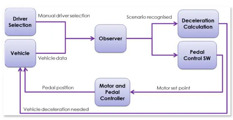
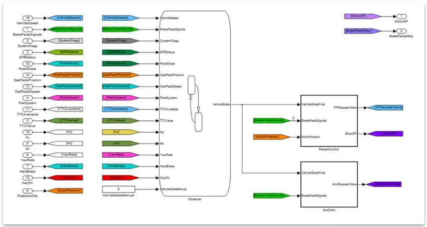
Chapter 5 shows the logical architecture behind the software implementation (paragraph 5.2). This is the rationale flow of the information among user, vehicle and software implementation. The core of the scenario detection is inside “Observer” module (Figure 25): it is the responsible of braking scenario recognition starting from vehicle dynamic data. In this case, on user point of view, the recognition of the scenario is left to the system. The user could decide to not demand to the system this detection and force it via manual selection. In this case, the “Observer” doesn’t perform its job. In case of automatic scenario recognition, “Observer” computes vehicle data input as:
- Vehicle speed and longitudinal acceleration (derived from its speed); - Brake pedal position and apply speed (derived from its position); - Gas pedal position and release speed (derived from its position); - Engine speed;
- 3 axes accelerometers; - Road slope;
- Key on/off;
- Park system availability;
- TTC availability and (in case) its value;
Figure 25: SW Architecture
As output, the “Observer” calculates the relevant scenario as detailed in paragraph 3.6. The output could be:
50 - Braking action at low speed;
- Braking action at low speed with automatic parking system; - Emergency braking;
- Emergency braking with TTC information available; - Constant speed braking;
- Repeated hard braking;
- Keep the stopped vehicle on plain road before restart; - Keep the vehicle and adapt its position on a slope; - Stop the vehicle, key off and parking brake activation;
Once the scenario is defined, both modules “Deceleration Calculation” and “Pedal Control SW” take as input the scenario and find out which curve has to be applied.
They calculate respectively the deceleration needed and the pedal force feedback basing on the data shown within chapter 4. The deceleration needed is sent directly to the vehicle ECUs in order to perform the braking action in the 4 wheels corners; the “Pedal Control SW” instead calculates a position of an electric