Available Online at www.ijpret.com 122
INTERNATIONAL JOURNAL OF PURE AND
APPLIED RESEARCH IN ENGINEERING AND
TECHNOLOGY
A PATH FOR HORIZING YOUR INNOVATIVE WORK
MODELING AND SIMULATION OF BLDC MOTOR BY USING MATLAB
MS. RUTUJA A. BHAT1, PROF. P. S. JADHAV2, MS. KSHITIJA A. BHAT3
1. Department of Electrical Engineering, PES Modern College of Engineering, Pune, Maharashtra, India.
2. Assistant Professor, Department of Electrical Engineering, PES Modern College of Engineering, Pune, Maharashtra, India. 3. Department of Mechanical Engineering, OM College of Engineering, Inzapur, Wardha, Maharashtra, India.
Accepted Date: 20/01/2015; Published Date: 01/02/2015
\
Abstract: The aim of this paper is modelling of three phase Brushless Dc Motor (BLDCM) using MATLAB .The performance of BLDC system is simulated. BLDC motors are gaining popularity rapidly now-a-days. BLDC motors are highly used in industries such as Aerospace, Appliances, Automotive, Consumer, Medical, Industrial, Automation Equipment and Instrumentation. BLDC motors do not use brushes for commutation, instead of that, they are electronically commutated. As compared to Brushed DC motor and Induction motor, BLDC motors have many advantages. Based on the mathematical model of BLDC motor, a control strategy of BLDC motor is proposed, then a simulation analysis is made using modern simulation software MATLAB/SIMULINK, which can provide accurate predictions of the system behaviour.
Keywords: BLDC, MATLAB/SIMULINK, control strategy, and simulation.
Corresponding Author: MS. RUTUJA A. BHAT
Access Online On:
www.ijpret.com
How to Cite This Article:
Rutuja A. Bhat, IJPRET, 2015; Volume 3 (6): 122-132
Available Online at www.ijpret.com 123 INTRODUCTION
A DC Motor is a device which is used to convert electrical energy into the mechanical energy. Number of electrical equipments is required to be supplied with kinetic energy for linear or rotating motion requirement.
BLDC motors are a type of synchronous motor. That means the magnetic field generated by the stator and the magnetic field generated by the rotor rotate at the same frequency. BLDC motors do not experience the” slip” that is normally seen in induction motors. BLDC motors come in single-phase, 2-phase and 3-phase configurations. Corresponding to its type, the stator has the same number of windings. Out of these, 3-phase motors are the most popular and widely used.
A motor that retains the characteristics of a dc motor eliminating the commutator and the brushes is called a Brushless DC motor. In many cases, Brushless DC (BLDC) motors can replace conventional DC motors. There are no brushes on the rotor. They are driven by dc voltage but current commutation is done by solid state switches that mean, the commutation is done electronically. The BLDC motors are available in many different power ratings ranging from very small motors as used in hard disks to large motors in (EV s) i.e. electric vehicles. [1] BLDC motors are highly used in industries such as Aerospace, Appliances, Automotive, Consumer, Medical, Industrial, Automation Equipment and Instrumentation since it has high reliability, high power density, low maintenance requirement, lower cost and lower weight. BLDC motors have many advantages over brushed DC motors. Some of these are:
Higher efficiency
Higher speed ranges
Noiseless operation
Better speed versus torque characteristics
Long operating life
Higher dynamic response
Available Online at www.ijpret.com 124
Here, in this paper, we are employing SPWM technique
In this method the speed is controlled in a closed loop by measuring the actual speed of the motor. The error in the set speed and actual speed is calculated. A proportional plus integral (PI) controller is used to amplify the speed error and adjust the pwm duty cycle. [3]By analysing the motor speed, torque and other parameters and imposing different control algorithm on the system, a best strategy can be adopted. Lastly, here, in this paper, a simulation model of BLDC motor is built, based on mathematical analysis, the reliability and validity of this method has been proved by simulation results.[4]
2. TYPE OF CONTROL TECHNIQUES OF PMBLDC MOTOR.
There are various control techniques available for controlling PMBLDC motor. But basically two methods are available i.e. sensor control and sensorless control. Some design utilised both to provide high torque at high load and high efficiency at low load. Such a type of hybrid design allows the control of harmonic current. [5]
Various senseless methods for BLDC motors are analyzed in [6-10]. Modeling of BLDC is given in [3]. The speed control of brushless drive employing PWM technique using digital signal processor was proposed in [6]. A PSO based optimization of PID controller for a linear BLDC motor is given in [7-8].Speed Control of BLDC based on CMAC & PID controller is explained in [9]. Direct torque control and indirect flux control of BLDC motor with non-sinusoidal back emf method controls the torque directly and stator flux amplitude indirectly using d axis current to achieve a low-frequency torque ripple free control with maximum efficiency[10] ,[11]Proposes the simulation of brushless DC motor on SVPWM control.
This paper deals with the control strategy of using SPWM to control the system. An accurate model of complete system is required to control the system.
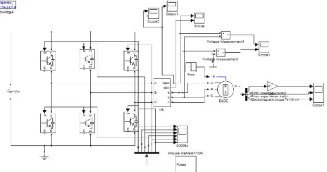
3. SIMULINK MODEL OF BLDC MOTOR
Here, we are considering two models: open loop model and the closed loop model with speed feedback of BLDC motor. In both the models, we are using six MOSFET s as a three phase inverter, to which the BLDC motor is connected. In case of closed loop structure, speed feedback is given to the pulse generator along with a reference speed of 1500 rpm. Here the pulses are generated. The error signal is given to the MOSFET switches and then these signals are passed over to the BLDC motor.
Available Online at www.ijpret.com 125 Fig -3(a): Open loop model with no feedback
Closed loop model is shown below:
Fig -3(b): Closed loop model with feedback
4. SIMULATION RESULTS
Fig shows the simulation results with following parameters; R=0.1Ω, L=1 mH, M=0.5 mH, J=0.002kg.sq.m. Tl=0.5 Nm and simulation time = 0.5 s.
(i). Simulation results for open loop
For speed, angle theta and electromagnetic torque, the waveforms are;
Available Online at www.ijpret.com 126
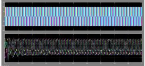
Voltage and current waveforms:
Fig -4(i) (d), (e): Output waveforms for voltage & current.
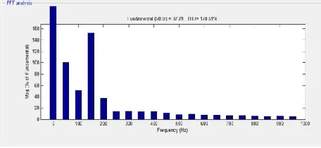
For open loop simulation model, the FFT analysis is given as:
For speed
Fig -4(i) f: FFT analysis for speed
For theta
Available Online at www.ijpret.com 127
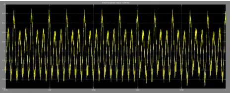
For electromagnetic Torque
Fig -4(i) h: FFT analysis for electromagnetic torque
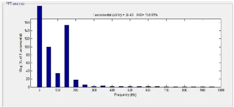
For voltage
Fig -4(i) d: FFT analysis for voltage
For current
Fig -4(i) i: FFT analysis for current
(ii). Simulation results for closed loop
Available Online at www.ijpret.com 128 Fig -4(ii) a: Output waveform for speed
For rotor angle theta
Fig -4(ii) b: Output waveform for theta
For electromagnetic torque
Available Online at www.ijpret.com 129
For current
Fig -4(ii) d: Output waveform for current
For voltage
Fig -4(ii) e: Output waveform for voltage
For closed loop simulation model, FFT analysis is given as:
For speed:
Available Online at www.ijpret.com 130
For theta:
Fig 4(ii) g: FFT analysis for thet
For electromagnetic torque:
Fig -4(ii) h: FFT analysis for electromagnetic torque
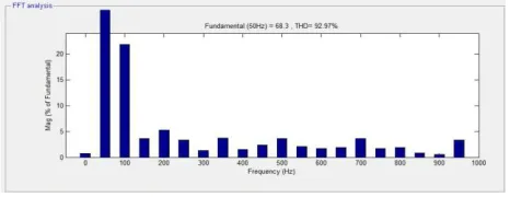
For voltage:
Fig -4(ii) i: FFT analysis for voltage
For current:
Available Online at www.ijpret.com 131 5. CONCLUSION
The modeling procedure proposed here in this paper helps in simulation of various types of BLDC motors. The fruitful simulation results show that such a modeling is very useful in studying the drive system before taking of the dedicated controller design.
REFERENCES
1. G. Prasad, N Sree Ramya, P.V.N. Prasad, G. Tulasi RamDas.” Modelling and Simulation
Analysis of the Brushless DC Motor by using MATLAB”. International Journal of Innovative Technology and Exploring Engineering (IJITEE), ISSN: 22783075, Volume -1, Issue-5, October 2012.
2. Chinch- Tsuns, Chi, Shih-An, Yin,”Speed Measurement of a General DC Brushed Motor
Based on Sensorless Method”. IEEE paper 2012 978-1-4673-4584-2.
3. Vinod Kr Singh Patel, A. K. Pandey, “Modeling and Simulation of Brushless DC Motor Using
PWM Control Technique”, International Journal of Engineering Research and Applications (IJERA) ISSN: 2248-9622 www.ijera.com Vol. 3, Issue 3, May-Jun 2013, pp.612-620
4. Congzhao Cai, Hui Zhang, Jinhong Liu Yongjun Gao, “Modeling and Simulation of BLDC
motor in Electric Power Steering”, IEEE 2010 paper 978-1-4244-4813-5/10.
5. ”New Approach to Rotor Position Detection and Precision Speed Control of the BLDC
Motor”, Yong-Ho Yoon Tae-Won Lee Sang-Hun Park Byoung-Kuk Lee Chung- 1-4244-0136-4/06/$20.00 '2006 IEEE 8
6. G. Madhusudhanrao, B.V. Sanker Ram, B. Sampath Kumar, K. Vijay Kumar, “Speed Control
of BLDC Motor using DSP”, International Journal of Engineering Science and Technology Vol.2 (3), 2010.
7. Yingfa Wang, Changliang Xia, Zhiqiang Li, PengSong,” Sensorless Control for BLDC motor
using support vector machine based on PSO”, 2009IEEE
8. Mehdi Nasri, Hosse in Nezamabadi-Pour, Malihemaghfoori, “A PSO-Based optimization of
PID controller for a Linear BLDC Motor” Proc. Of World academy of Science Engg &Tech, Vol. 20, April 2007.
9. Zhiqiang Li & Changliangxia, “Speed Control o fBLDC based on CMAC & PID controller” Proc.
Of 6th World congress on Intelligent Control & Automation. China, June 21-23, 2006.
10.Salih Baris Ozturk, Hamid A. Toliyat, “Sensorless Direst Torque and Indirect Flux Control of
Available Online at www.ijpret.com 132
11.Yi Huang, Chunquan Li,”Model and System Simulation of Brushless Dc motor based on