ISSN: 1942-9703 / CC BY-NC-ND Abstract—Security system is one of the common problems to
protect an environment such as personal house or a warehouse. There are numerous methods and technologies available to be used as part of a security system. However, creating an effective and efficient security system is not a trivia task. In this paper, we present a security system that offers a better efficiency. It has the capability to identify when an intruder enters a warehouse and send a report to registered user via short message service (SMS). It is based on vibration and infrared to detect intruders. Our objective is to describe the technology, development process, and the result of using the system in real case. We specifically use Raspberry Pi as the microcontroller of our system due to its ease of use. In our test case, we implemented our security system in a warehouse and observe the effectively of our system to detect intruders. We test a few possibilities of intruder’s method to enter the warehouse and record the response of the system. The result shows that the system has effectively record the event and send a report via SMS to registered user. The average time difference between intrusion event and notification received by user is 5 to 10 seconds.
Index Terms—Security-System, Raspberry-Pi, Infrared Sensor, Vibration Sensor, Microcomputer.
I. INTRODUCTION
ECURITY system is one of the most demanding feature in our current society. The availability of an effective and established security system has become a necessity in everyday activity. Using only man power for security is no longer considered as an effective method. The cost to hire adequate person to cover a certain area and the inability to guarantee an effective 24-hour security are two of the biggest problem in man-based security. Hence, the role of technology has replaced man based security as the vital part of the security. There are many methods and technology available to develop a solid security system. However, the use these technologies to achieve a better security should be in line with efficiency. For example, while recording a 24-hour event is considered as the most effective system, it is still considered
Manuscript received October 9, 2017. This work was supported by the Kementerian Riset, Teknologi, dan Pendidikan Universitas Sumatera Utara (USU), Medan, Department of “Lembaga Penelitian USU (Research Centre of USU), in contracts: 80 / UN5.2.1 / PPM / KP-TALENTA USU / 2017.
Poltak Sihombing, Jos Timanta Tarigan, Benyamin Ginting, and Dahlan Sitompul are with Universitas Sumatera Utara, Faculty of Computer Science and Information Technology, Universitas Sumatera Utara, e-mail: [email protected].
inefficient due to redundant amount of recording that contains no crucial information. Moreover, the cost of maintaining the system to work in 24-hour can be extremely expensive.
The objective of this work is to introduce a method that solves the efficiency problem without jeopardizing the effectiveness of the security system. The proposed system uses two sensors, infrared and vibration, to detect occurring intrusion event. In addition, the system also able to perform a one-way communication to registered user in order to notify the user should any event is occurred. We build this system using Raspberry Pi as its main board. Moreover, the system will be connected to a PC that will operate as an SMS gateway.
The paper is presented as follows: in the next section 2, we will discuss any works/research that has been done related to our topic. Section 3 will discuss the overall architecture of our proposed system. The implementation will be presented in section 4 followed by testing and results in section 5. Section 6 summarizes the work that has been presented in this paper.
II. RELATEDWORKS
Raspberry Pi [1] is a small single-board computer hardware that allows developers to study basic computer system. Developed and firstly introduced by Raspberry Pi Foundation in 2012, the purpose of this device is to simplify computer hardware while decreasing its cost. It's simplicity and the capability to work as stand-alone computer hardware gives opportunity for students and researchers to create a dedicated computer for a specific task. While the size of Raspberry is relatively small compared to a common computer, Raspberry Pi is capable to contain common computer hardware such as processor, memory, GPU, and storage. It also has the capability to run basic operating system such as Linux and Windows. There are numerous research based uses Raspberry Pi as its platform.Russel Barnes writes several projects using raspberry pi [2]. Shaijupaul, et al writes Android based Home Automation Using Raspberry Pi [3]. Pawan Singh, et al has done review paper on Smart GSM based Home Automation System [4]. The wireless remote car uses Raspberry Pi as its main board.
Passive Infrared sensor is an electronic sensor that detects an event based on changes of infrared light radiating from objects in its view. The operating principle of infrared sensors is that all objects emit heat energy in the form of radiation. The radiation is mostly invisible since it emits at infrared
Security System Based on Vibration and
Infra-Red Sensors Using Raspberry
Poltak Sihombing, Jos Timanta Tarigan, Benyamin Ginting, and Dahlan Sitompul
wavelength. An infrared sensor is able to detect the radiation emitted by objects. Usually, the sensor does not require to emit any energy to perform the detection, hence the term passive is embedded to the sensor. Infrared vision is mostly used to detect objects in dark environment. In the case of security, where the intrusions mostly occurred during the night to avoid the crowd, the use of infrared vision can be very important to record the event. Fig.2 shows the Infrared wavelength.
Fig. 1. Infrared Wavelength just below the visible light spectrum. (Image courtesy of Khan Academy [5])
Most of the works that use passive infrared sensor are either related to security based intrusion detection or internet-of-things tools development.
III. SYSTEMARCHITECTURE
A. Overview of Project
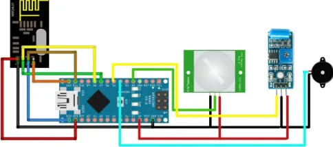
In this section, an experimental setup is implemented with real instruments. An Arduino controller is used along with the raspberry pi to achieve the desired result. A Web based system is developed using the Smart Access feature of the Raspberry pi. The equipment used in experimental setup is shown in Fig. 2 below.
Fig. 2. The block diagram of our Project.
The system contains 4 main components: camera, infrared sensor, vibration sensor, and a personal computer as a SMS Gateway. The system workflow can be summarized as follows: the two sensors, infrared and vibration are continuously sensing the targeted area. If one of the sensor senses an event, it will send a signal to Raspberry Pi. Raspberry Pi, acting as the main controller, sends the signal to a connected SMS Gateway. The SMS Gateway will then build
a message based on the detected event and send the message to a registered user.
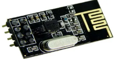
Physically, the system is divided into 2 main modules: sensor module and server module. The sensor module connects contains and manage the two sensors while the server module sends notification from sensors to registered user. The sensor module uses Arduino Uno as its main board while the server module uses Raspberry Pi. Each of these modules has a wireless device to communicate with each other. We use NRF24L01 as our wireless communication tools. This device, as shows as the image below, is a microcontroller that capable to send via Radio Frequency 2.4 GHz. It works on 3V DC power source and compatible with Arduino and Raspberry Pi. Fig.3 shows the Microcontroller model nRF24L01.
Fig. 3. Microcontroller model nRF24L01
We will go through each module in the next 2 subsections.
B. Sensor Module
The sensor module is responsible to detect intrusions by detecting infrared radiation changes and vibration. Hence, the module uses two sensors to perform this task; passive infrared sensor and vibration sensor. We also add the capability to produce a sound in this module to give a notification when the sensors detect changes. All of these devices are connected to an Arduino Nano as the main board. Fig.4 shows the Physical Form of Arduino Nano and Fig.5 shows the Architecture Schema of Arduino Nano.
ISSN: 1942-9703 / CC BY-NC-ND Fig.5. The Architecture Schema of Arduino Nano.
For this research, we use a Passive Infrared Sensor from Adafruit with Arduino compatibility as shown as the image below. This sensor has the capability to detect motion from averagely 7 meter’s. Its cone shaped camera has a 120 degree viewing angle. As for the vibration detection, we use sensor model SW-40 as shown in the image below. This sensor has a working voltage between 3.3 V to 5 V and will pass LOW output when there is no vibration detection, and HIGH if otherwise. The last part connected to the main board is a Buzzer. This device is responsible to generate a sound when it receives electrical current. We use 3.5V-5V Standard Passive Buzzer Model for the current system as shown on the image below. It is compatible with Arduino and capable to produce a sound with an adequate volume.
Fig. 6. a) Infrared Sensor, b) SW-40 Vibration Sensor, and c) Buzzer
C. Server Module
The Server module is responsible to generate notification to user regarding the detected signal from sensor module. When it received a signal from sensor module, it formed a message regarding the detection information and sends it to registered user. To perform this task, this module requires a modem connected to the device. For the server module, we use a Raspberry Pi as the main board. Our current work uses Raspberry Pi 2 with 900 MHz 32 bit quad-core ARM Cortex-A7 as its CPU. It also has 1 GB Random Access Memory and has a built in GPU. We use this device to act as our SMS gateway that sends notification to user.
IV. IMPLEMENTATION
The first part of the implementation process is to connect all of the devices described above. In this section, we will go through the process of connecting the devices based on the architecture.
A. Connecting NRF24L01 with Raspberry Pi B+ and Arduino
Since both modules require a form of communication, we install NRF24L01 to both Arduino Nano and Raspberry Pi. The installation is done by connecting the pin accordingly. NRF24L01 has 7 pins; 2 pins for power source (VCC and GND) and 5 pins for digital data transfer. Raspberry Pi has 40 Pin GPIO (General Purpose Input Output) and Arduino Nano has 14 pins for digital input output and 6 pins for analog input output. Table 1 shows which pins should be connected to each microcontroller board.
TABLE I
THE CONNECTING OF RASPBERRY PI WITH ARDUINO NANO NRF24L01 Raspberry Pi Arduino Nano
VCC 3.3V 3.3V
GND GND GND
CSN GPIO 8 Digital 10
CE GPIO 17 Digital 9
MOSI GPIO 10 Digital 11
MISO GPIO 9 Digital 12
SCK GPIO 11 Digital 13
B. Connecting Sensors and Buzzer to Arduino Nano
The next step of the installation is to connect the sensors to Arduino Nano Microcontroller. There are two sensors to be connected: Passive Infrared and Vibration Sensor. Both sensors require power source; hence each sensor is connected to GND pin and 3.3V pin on the Arduino Nano. For digital data transfer, Passive Infrared Sensor is connected to Digital 5 pin and Vibration Sensor is connected to Digital 2 pin. Additionally, we connect buzzer to Arduino Nano simply by using VCC and GND pin. The Buzzer does not require data transfer. The architecture of the sensor module can be seen in the diagram below.
C. Server Module
The main purpose of the server module is to send notification to user. This notification is sent via short massage system. The main board, Raspberry Pi, runs Debian, a variant of Linux that works on Raspberry Pi. We use Gammu SMS Daemon to support our SMS Gateway application and attach a GPRS Modem to the Raspberry mainboard via USB plugin. Fig. 8 shows the overall architecture of the server module.
Fig. 8. The overall of the server module.
The notification system is designed to send an SMS each time the sensor detects changes. However, designing the notification system to send an SMS each time the sensor senses a changes may cause SMS spamming. To avoid this problem, we set a restriction in the system to only send one notification per minute. Hence, the system will ignore any changes sent from the sensor for one minute after a notification is sent. We also set another restriction to only send one notification per event; thus a multiple and continuous changes will be treated as a single event.
D. Flowchart and Program
i. Flowchart of the security system project
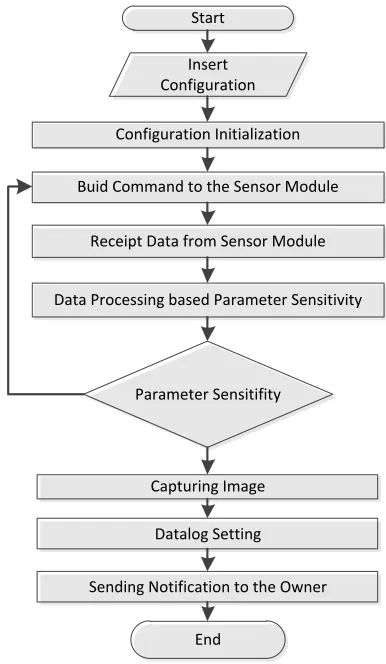
In this section, we briefly describe the performance of the system created. The first step is raspberry pi as the server module that initializes the settings and starts the service. The raspberry pi then creates a string-shaped command and sent to the sensor via the NRF2401L module, such as device information, sensors and alarm information. When the command is received by the sensor module, the sensor module will respond whether the sensor data needs to be sent or the alarm needs to be turned on. All command information is in the server module. The sensor module will send back the required server data module such as sensor value information, and then the server module checks whether the data passes through the sensitivity. If it exceeds or equal the sensitivity data that has been created, then the raspberry pi will take a picture by pi camera and record the log data in the database then do notification via SMS or internet to hand pone homeowners. Fig.9 shows the flowchart of the project.
Start
Insert Configuration
Configuration Initialization
Buid Command to the Sensor Module
Receipt Data from Sensor Module
Data Processing based Parameter Sensitivity
Parameter Sensitifity
Capturing Image
Datalog Setting
Sending Notification to the Owner
End
Fig. 9. The flowchart of the security system project
ii. Software Program
The software used to create the program is the Arduino editor and compiler. The compiled *.ino file extension will be uploaded into the arduino microcontroller. Writing code/ script embedded in arduino IDE software can be seen in fig. 10.
ISSN: 1942-9703 / CC BY-NC-ND iii. Experimental set up
The experiments performed are shown in figure 11 below.
Fig. 11. The experimental set up
The installations of raspberry pi start by install the raspberry’s Card and connect the cables. Take the raspberry’s card adaptor out, retrieve the micro card, and slot it into the Raspberry Pi; this is very important, as the Raspberry Pi won’t be able to turn on properly otherwise. To start with, we’ll need to plug in an HDMI (High definition Multimedia Interface) cable between the Raspberry Pi and our screen, an Ethernet cable to our router (or a USB Wi-Fi dongle), along with a mouse and keyboard. Finally, when everything we need is plugged in, we can attach the power cable to the Raspberry Pi.
V. TESTANDRESULTS
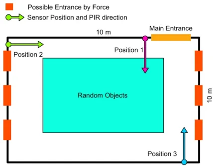
For testing purpose, we put our device in a 10x10 meters warehouse. We register 1 user as the registered user. We observed the sensitivity of the sensor and the capability to detect various type of intrusion in order to figure out the best condition for the system to work optimally. We collected data from 3 different sensor positions. We also observed the average time from the moment the sensor detects and event to the time of notification received by the user. The image below shows the condition of our test case.
Fig.12. The Part of our test case condition
Based on our observation we noticed that sensors on position 1 can easily detect intrusion using the main entrance due to the vibration caused by the door. The PIR is also able to detect the intrusion as soon as the intruder enters the perimeter. The wide angle of PIR's point of view is able to cover most part of the entrance. However, there is a narrow blind spot near the right of the door that can be used to enter the room undetected. Position 2 is optimal only to detect intrusions using the left window. There are 100% chances that the vibration sensor detects intrusion from the two nearest windows while it only able to detect 70% of entrance from the farthest left window. The PIR is unable to reach the main entrance which is averagely 8.5 meters from the sensor. Position 3 was able to detect the all intrusions from the nearest 2 windows on the right. However, 50% of the intrusions using the window near the main entrance were undetected. It is also unable to detect intrusions from the main entrance but able to detect if the intruder gets closer to the sensor. It is also important to note that vibration sensor in irrelevant on position 3.
Our test also shows that the notification system works successfully. The average time difference between intrusion event and notification received by user is 5 to 10 seconds. Most of the delay happened during the SMS sending process. We also noticed that the system does not send more than 1 SMS per minute. The notification system also successfully ignores continuous event.
VI. CONCLUSION
REFERENCES
[1] Raspberry pi.[Online].Available:http://www.raspberrypi.org/
[2] Russel Barnes, The Official Raspberry Pi Project Book. Available: https://www.raspberrypi.org/magpi-issues/Projects_Book_v1.pdf [3] Shaijupaul, Ashlin Anthony, Aswathy B, ''Android based Home
Automation Using Raspberry Pi,” IJCAT - International Journal of Computing and Technology, vol. 1, Issue 1, February 2014, pp 143 - 147.
[4] Pawan Singh, Krupachotalia, SanketPingle,” Review paper on Smart GSM based Home Automation System," International Research Journal of Engineering and Technology (IRJET), vol. 3, Issue: 04, pp 1838-1843, 2016.
[5] Khan Academy, Available: https://khanacademy.zendesk.com/hc/en-us/articles/
[6] Nikhil Agrawal, Smita Singhal, “Smart Drip Irrigation System using Raspberry pi and Arduino,” International Conference on Computing, Communication and Automation (ICCCA2015) ISBN:978-1-4799-8890 -7/15/$31.00 ©2015 IEEE.
[7] Bendel, R.B., Afifi, A.A., “Comparison of stopping rules in forward stepwise regression,” J. Amer. Stat. Assoc., vol. 72, pp. 46-53, 1977. [8] Meg, B. C., “Determining the optimum number of predictors for linear
prediction equation,” Amer. Meteo. Soc., Vol. 116, pp. 1623-1640, 1988. [9] Miller, A.J., Subset selection in regression. Monographs on statistics
and applied probability 40. Chapman and Hall, 1990.
[10] Palm, R., De Bast, A., Lahlou, M., “Comparaison des modèles agrométéorologiques de type statistique empirique construits à partir de différents ensembles de variables météorologiques,” Bull. Rech. Agron. Gembloux, vol. 26, pp. 71-89, 1991.
[11] Roecker, E.B., “Prediction error and its estimation for subset-selected models,” Technometrics, vol. 33, pp. 459-468, 1991.
[12] Ali M., V laskamp J.H.A, Eddiny N.N., Falconer B. and Oram C., “Technical Development and Socioeconomic Implications of the Raspberry Pi as a Learning Tool in Developing Countries," 5th Com puter Science and Electronic Engineering Conference (CEEC), pp. 103 -108, 2013.
[13] Yoon D., Bae D., Ko H. and Kim H., "Implementation of Home Gateway and GUI for Control the Home Appliance," The 9 the International Conference on Advanced Communication Technology, pp. 1583-1586, 2007.
[14] Ok S. and Park H., “Implementation of initial provisioning function for home gateway based on open service gateway initiative platform," The 8th International Conference on Advanced Communication Technology,
pp. 1517-1520, 2006.
[15] Kushiro N. , Suzuki S., Nakata M., Takahara H. and Inoue M., “Integrated home gateway controller for home energy management system,” IEEE International Conference on Consumer Electronics, pp. 386 - 387, 2003
[16] ChandankumarSahu, PramiteeBehera, “A Low-Cost Smart Irrigation Control System,” IEEE Sponsored 2nd International Conference on Electronics and Communication System (ICECS 2015).
[17] R. Hussain, J. Sehgal, A. Gangwar, M. Riyag, “Control of irrigation utomatically by using wireless sensor network,” International journal of soft computing and engineering, vol. 3, issue 1, pp. 324 – 328, 2013. [18] Megat N.M., Mohamed Noor, “Community based home security system
using wireless mesh network,” International Journal of Academic Research Part A, vol. 5, no. 5, pp. 73-79, 2013 DOI: 10.7813/2075-4124.2013/5-5/A.9
[19] Haghighi, M., and Cliff, D., “Sensomax: An agent - based middle are for decentralized dynamic data - gathering in wireless sensor networks,” In Collaboration Technologies and Systems (CTS), 2013 International Conference on IEEE, pp. 107-114, 2013.
[20] Cagnetti, M., Leccese, F., and Trinca, D., “A New Remote and Automated Control System for the Vineyard Hail Protection Based on ZigBee Sensors, Raspberry-Pi Electronic Card and iMAX,” J. Agric.Sci. Technol. B, vol. 3, pp. 853-864, 2013.
Poltak Sihombing (PS) was born in Indonesia on March 17, 1962. He
received the Physics degree in Computation Physics from the University of Sumatera Utara, Medan, Indonesia, in 1988. The M.Sc. degree in Computer Science from the University of Indonesia (UI), Jakarta, Indonesia, in 1998, and the Computer Science Ph.D. Degree in Intelligent System Techniques from the Universiti Sains Malaysia (USM), Penang, Malaysia, in 2010. He has held lecturing positions at The University of
Sumatera Utara, Medan, Indonesia. Since 2011, He has been the head of Computer Science Department on Faculty of Computer Science and Information Technology, University of Sumatera Utara. His research interests cover the intelligent system techniques, instrumentation engineering and information retrieval systems. He is a member of APTIKOM (Assosiasi Perguruan Tinggi Informatika Komputer/ The Association of Universities Computer and Informatics). Since 2011, he served as a secretary of North Sumatera and Aceh region.
Jos Timanta Tarigan was born in January 1985. He is a lecturer at Computer
Science Department, Faculty of Computer Science and Information Technology (Fasilkom-TI) Universitas Sumatera Utara, Medan, Indonesia. He received his bachelor degree in computer science from University of Indonesia in 2006. After working in several IT company for two years, he decided to continue his study and received his master degree in Advance Computer Graphic in 2011 from Linkoping University, Sweden. Since then, he has been a lecturer in Universitas Sumatera Utara. He is currently a member of IEEE an APTIKOM. email: [email protected].
Benyamin Ginting (BG) was born in Indonesia on February, 1991 and was
writing computer code by the time he was 17. He received the Diploma in Management Informatics in Telkom Polytechnic (now Telkom University), Bandung, Indonesia, in 2012. Degree in Computer Science from the University of Sumatera Utara, Medan, Indonesia, in 2017. From 2011 to 2017 he worked as Programmer at several company in Indonesia, eventually as a Computer Scientist. He primary focus and inspiration for studies is Web Development. Much of his work has been on improving the understanding, design, and performance of parallel and networked computer systems, mainly through the application of data mining, statistics, and performance evaluation.
Dahlan R.P. Sitompul, Currently he is a lecturer at Computer Science