MICROSTRIP PATCH ANTENNA FOR S-BAND APPLICATIONS
1
K.V.L.Bhavani, 1*B.T.P.Madhav, 1P.Poorna Priya,
2Y.Joseph Manoj Reddy, 2N.Srinivas Sri Chaitanya, 2N.Krishna Chaitanya
1
Department of ECE, K L University, Guntur DT, AP, India 2Project Students, Department of EEE, K L University, AP, India
Email: [email protected], [email protected]
ABSTRACT
The proposed antenna exhibits dual resonance at 2.524GHz and 3.222GHz due to the multi resonance characteristics of a single patch. Rectangular patch shape of dimensions 30X40mm is etched on the RT-duroid substrate material having dielectric constant εr=2.2 with loss
tangent tan δ=0.0009. Orthogonal feed is given at (6, 6) position. The resultant characteristics of the proposed antenna is compared with the rectangular MSPA with single feed at (6,0) and single feed at (0,6) positions. The theoretical results are compared with the simulated data using CONCERTO software which are in close agreement. Further returnloss, 2D radiation pattern, 3D radiation pattern, Total E field and H Field, power, axial ratio, probe impedance results for the proposed antenna are calculated and presented.
Keywords:Patch antenna, Dual Band MSPA, Orthogonal polarization
1. INTRODUCTION:
Microstrip patch antennas in general have a conducting patch printed on a grounded microwave substrate. The attractive features like low profile, light weight, easy fabrication and conformability to mounting hosts makes patch antenna as a better option in wireless communications[1-4]. Recent advances in wireless applications at S-Band that demands frequency reuse or polarization diversity involves dual band antennas rather than broad band antennas. In this paper a simple design for dual frequency rectangular microstrip patch antenna with orthogonal feed is proposed and the performance is evaluated with the normal single feed rectangular MSPA. Use of circulator or diplexer is avoided by the proposed antenna for dual band operation for wireless communications [5-7].
Dual frequency operation f01 and f10 for the proposed antenna is achieved by orthogonal feed
located at (x, y) location.
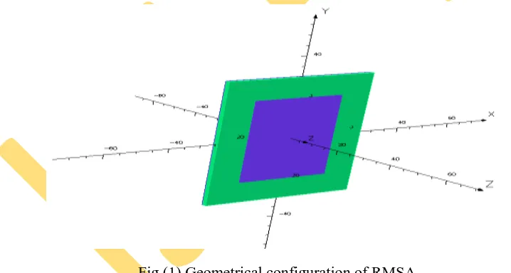
3. DESIGN SPECIFICATIONS FOR THE PROPOSED ANTENNA:
The geometrical configuration of proposed antenna is shown in Fig (1).Length of the patch is 30mm and width of the patch is 40mm.which is designed on a 50X60 mm RT-duroid substarte.Fig (2) depicts the feed locations for the proposed design indicated as A,B and C. If MSA fed at A it operates at single frequency and if it is fed at B it operates at other single frequency. For single feed dual band operation MSA should fed at C which is called orthogonal feeding so that it resonates at two frequencies.
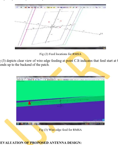
Fig (2) Feed locations for RMSA
Fig (3) depicts clear view of wire edge feeding at point C.It indicates that feed start at 0 and extends up to the backend of the patch.
Fig (3) Wire edge feed for RMSA
4. EVALUATION OF PROPOSED ANTENNA DESIGN:
Variation of return loss as a function of frequency for different feed locations A (6, 0), B (0, 6), A along with B and only at C (6, 6) are analyzed mainly.
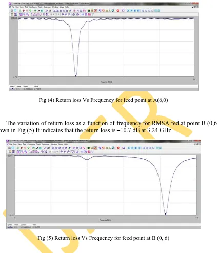
Fig (4) Return loss Vs Frequency for feed point at A(6,0)
The variation of return loss as a function of frequency for RMSA fed at point B (0,6) is shown in Fig (5) It indicates that the return loss is –10.7 dB at 3.24 GHz
Fig (5) Return loss Vs Frequency for feed point at B (0, 6)
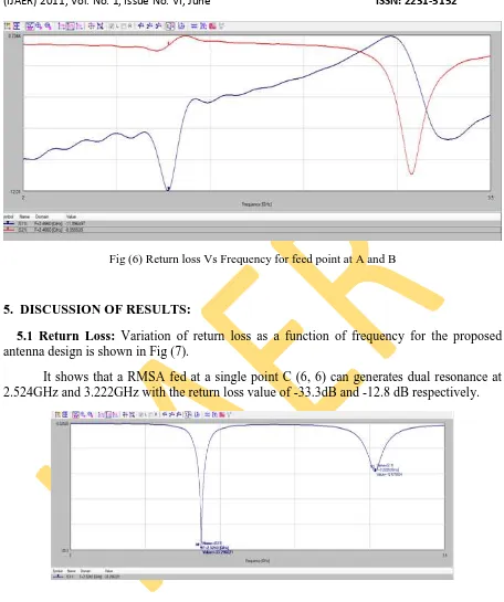
Fig (6) Return loss Vs Frequency for feed point at A and B
5. DISCUSSION OF RESULTS:
5.1 Return Loss: Variation of return loss as a function of frequency for the proposed antenna design is shown in Fig (7).
It shows that a RMSA fed at a single point C (6, 6) can generates dual resonance at 2.524GHz and 3.222GHz with the return loss value of -33.3dB and -12.8 dB respectively.
Fig (7) Return loss Vs Frequency for feed point at C (6,6)
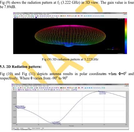
Fig (9) shows the radiation pattern at f2 (3.222 GHz) in 3D view. The gain value is found to
be 7.89dB.
Fig (9) 3D radiation pattern at 3.222GHz
5.3. 2D Radiation pattern:
Fig (10) and Fig (11) depicts antenna results in polar coordinates when Φ=00 and 900 respectively. Where θ varies from -900 to 900
Fig (11) 2D radiation pattern for Φ=900
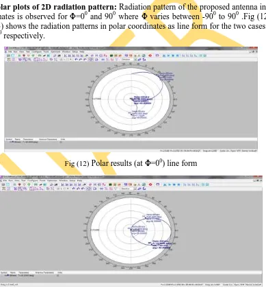
5.4 Polar plots of 2D radiation pattern: Radiation pattern of the proposed antenna in polar coordinates is observed for Φ=00 and 900 where Φ varies between -900 to 900 .Fig (12) and Fig (13) shows the radiation patterns in polar coordinates as line form for the two cases Φ=00 and 900 respectively.
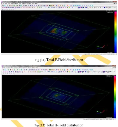
Fig (14) Total E-Field distribution
Fig (15) Total H-Field distribution
5.6 current distributions in linear and log form:
Fig (16) current distribution in line form Fig (17) current distribution in log form
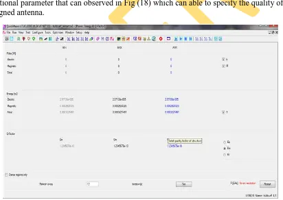
5.7 Quality factor and energy:
Electric field energy, magnetic field energy and total filed energy from the proposed antenna are calculated by CONCERTO and same is presented in Fig (18).The quality factor is the additional parameter that can observed in Fig (18) which can able to specify the quality of the designed antenna.
[4] GAO, S. C., LEE, L. W., YEO, T. S., LEONG, M. S., A Dual-Frequency Compact Microstrip Patch Antenna, Radio Science, vol. 36, no. 6, pp. 1669-1682, 2001.
[5] ROY, J. S., GHOSH, J., A Multifrequency Microstrip Antenna, Microwave and Optical Technology Letters, vol. 46, no. 1, pp. 63-65, 2005.
[6] D. Orban and G.J.K Moernaut, “The Basics of Patch Antennas”, RF Globalnet, 31 August 2005. Available online on 15 June 2008 on www.orbanmicrowave.com/The_Basics_Of_Patch_Antennas.pdf.
[7] J. Ollikainen, M. Fischer, and P. Vainikainen, “Thin dual-resonant stacked shorted patch antenna for mobile communications,” Electron. Lett. 35, 437–438, March 18, 1999.
[8] L. Zaid, G. Kossiavas, J. Dauvignac, J. Cazajous, and A. Papiernik, “Dual-frequency and broad-band antennas with stacked quarter wavelength elements,” IEEE Trans. Antennas Propagat. 47, 654–660, April 1999.
[9] K. L. Wong and M. H. Chen, “Slot-coupled small circularly polarized microstrip antenna with modified cross-slot and bent tuning-stub,” Electron. Lett. 34, 1542–1543, Aug. 6, 1998.
[10] W. S. Chen, K. L. Wong, and C. K. Wu, “Inset microstripline-fed circularly polarized microstrip antennas,” IEEE Trans. Antennas Propagat. 48, 1253–1254, Aug. 2000.
[11] K. L. Wong and W. H. Hsu, “A broadband rectangular patch antenna with a pair of wide slits,” IEEE Trans. Antennas Propagat. 49, 1345–1347, Sept. 2001.
[12] C. L. Tang, C. W. Chiou, and K. L. Wong, “Broadband dual-frequency V-shape patch antenna,” Microwave Opt. Technol. Lett. 25, 121–123, April 20, 2000.