HP ProLiant DL380 G5 High Availability
Storage Server
Legal and notice information
© Copyright 1999, 2008 Hewlett-Packard Development Company, L.P.
Confidential computer software. Valid license from HP required for possession, use or copying. Consistent with FAR 12.211 and 12.212, Commercial Computer Software, Computer Software Documentation, and Technical Data for Commercial Items are licensed to the U.S. Government under vendor's standard commercial license.
The information contained herein is subject to change without notice. The only warranties for HP products and services are set forth in the express warranty statements accompanying such products and services. Nothing herein should be construed as constituting an additional warranty. HP shall not be liable for technical or editorial errors or omissions contained herein. WARRANTY STATEMENT: To obtain a copy of the warranty for this product, see the warranty information website:
http://www.hp.com/go/storagewarranty
Contents
1 Preparing for installation ... 7
About this document ... 7
Related documentation ... 7
Check kit contents ... 7
System components ... 8
Gather configuration information ... 11
2 Setting up an active/passive cluster ... 13
Install the hardware ... 13
Make the physical connections ... 13
Power on the storage components and log in ... 14
Set static IP addresses for each network connection ... 15
Join both storage servers to the domain ... 18
Log in to the MSA ... 20
Set up the Quorum disk ... 20
Map the quorum disk volume ... 22
Establish the private connection between Server 1 and Server 2 ... 22
Install the MPIO Driver on both storage servers ... 22
Initialize and format the Quorum disk ... 23
Run the Cluster Administrator ... 25
Create the Cluster ... 25
Verify that the active/passive cluster is operational ... 28
3 Setting up an active/active cluster ... 29
Create additional volumes in the MSA ... 29
Initialize and format the disks ... 29
Add cluster resources ... 30
Verify that the active/active cluster is operational ... 32
4 Adding components for optimal availability and redundancy ... 33
Figures
DL380 G5 front panel ... 8 1
DL380 G5 rear panel ... 9 2
MSA 2012sa front panel ... 10 3
MSA 2012sa rear panel components ... 10 4
Cabling diagram: Server 1 and Server 2 connections to the MSA ... 14 5
Launch the iLO2 Integrated Remote Console ... 15 6
Private connection status ... 16 7
Public connection status ... 16 8
Setting the private connection static IP address ... 17 9
Setting the public connection static IP address ... 18 10
Computer Name tab of System Properties ... 19 11
Computer Name Changes dialog box ... 19 12
Enter virtual disk name and RAID Level ... 21 13
Select drives to add to the virtual disk ... 21 14
Configure volumes for the virtual disk ... 21 15
Map the quorum disk volume ... 22 16
Initialize the quorum disk ... 24 17
Create new partition ... 25 18
Set cluster domain and name ... 26 19
Analyzing cluster configuration ... 26 20
Add cluster service account information ... 27 21
iLO 2 Integrated Remote Console Virtual Power Button ... 27 22
Adding a volume in the MSA ... 29 23
New Resource Wizard ... 31 24
Possible Owners page ... 31 25
Dependencies page ... 32 26
Tables
DL380 G5 front panel components ... 8 1
DL380 G5 rear panel components ... 9 2
MSA 2012sa front panel components ... 10 3
MSA 2012sa rear panel components ... 10 4
Configuration information ... 11 5
1 Preparing for installation
These instructions are intended for professionals who will be installing, setting up, and configuring the HP ProLiant DL380 G5 High Availability Storage Server. Experience with Microsoft® administrative procedures and system and storage configurations is required.
The DL380 High Availability Storage Server solution consists of two HP ProLiant DL380 G5 Storage Servers and one Modular Smart Array (MSA) 2012sa storage device configured in an active/passive or active/active cluster. The following instructions allow you to set up a basic active/passive or active/active cluster using a shared Quorum disk and basic file shares.
About this document
This document provides instructions for creating three types of cluster configurations, depending on your storage server hardware configuration:
• To set up an active/passive cluster with the default hardware configuration (2 NIC ports on each storage server), see “Setting up an active/passive cluster” on page 13.
• To set up an active/active cluster with the default hardware configuration, first set up an active/pass-ive cluster as described in “Setting up an active/passive cluster” on page 13, then complete ad-ditional steps as described in “Setting up an active/active cluster” on page 29.
• To set up an active/active cluster with an additional NIC adapter on each storage server for the highest availability and redundancy, see
“Adding components for optimal availability and redundancy” on page 33.
Related documentation
The following documents [and websites] provide related information:
• HP ProLiant Storage Server user guide
• HP StorageWorks 2012sa Modular Smart Array user guide
• HP Rack Rail Kit installation instructions
• HP ProLiant Server troubleshooting guide
• HP Integrated Lights-Out 2 User Guide
• Network Attached Storage (NAS) from HP StorageWorks: http://www.hp.com/go/NAS
• HP ProLiant Storage Server NAS File and Print Solutions: http://www.hp.com/go/storageservers
You can find these documents from the Manuals page of the HP Business Support Center website:
http://www.hp.com/support/manuals
• 1 HP StorageWorks Modular Smart Array (MSA) 2012sa storage device
• 6 power cords
• 1 Ethernet crossover cable
• 4 mini SAS 1M cables
System components
The following figures show components, controls, and indicators located on the front and rear panels of the DL380 G5 Storage Server and MSA 2012sa. For more detailed information about specific system components, see the HP ProLiant Storage Server user guide and HP StorageWorks 2012sa Modular Smart Array user guide.
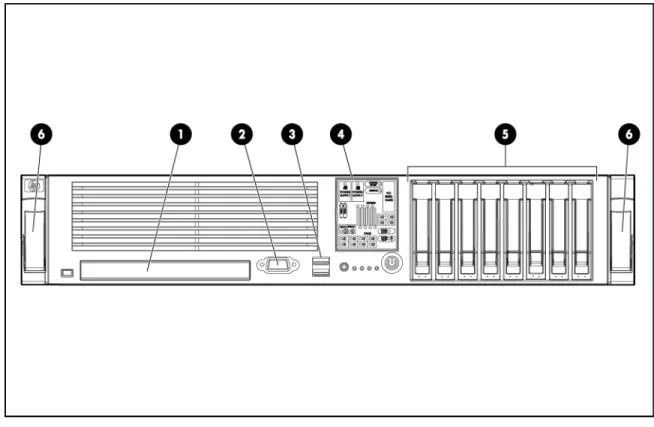
Figure 1 DL380 G5 front panel
Table 1 DL380 G5 front panel components Description
Item
DVD-RW drive 1
Video connector 2
USB connectors (2) 3
Systems Insight Display 4
Hard disk drive (HDD) bays 5
Quick release levers 6
Figure 2 DL380 G5 rear panel
Table 2 DL380 G5 rear panel components
Description Item
Description Item
USB connectors (2) (Black) 12
T-10/T-15 Torx screwdriver 1
Serial connector 13
External option blank 2
Mouse connector (Green) 14
NIC 2 connector 3
Keyboard connector (Purple) 15
NIC 1 connector 4
Expansion slot 1 16
Power supply bay 2 5
Expansion slot 2 17
Power supply LED 6
Expansion slot 3 18
Power supply bay 1 7
Expansion slot 4 (populated with an HP SC08Ge Host Bus Adapter)
19 Power cord connectors (Black)
8
Expansion slot 5 20
UID LED button 9
NIC/iLO 2 activity LED 21
iLO 2 connector 10
NIC/iLO 2 link LED 22
Video connector (Blue) 11
Figure 3 MSA 2012sa front panel
Table 3 MSA 2012sa front panel components Description
Item
Drive modules 1–12
Enclosure ID 13
Drive module LEDs 14
Status LEDs 15
Figure 4 MSA 2012sa rear panel components Table 4 MSA 2012sa rear panel components
Description Item
Power switch 1
Host ports 2
MUI (Service) port 3
CLI port 4
Ethernet port 5
Expansion port 6
Gather configuration information
Before you begin the process of installing and configuring the hardware, you will need the following configuration information. For easy reference during installation, fill in the Value columns with the appropriate values for your network.
Table 5 Configuration information
Server 2 Value Server 1 Value Notes Item
Local network information
If unknown, contact your network ad-ministrator
Public-facing static IP address
If unknown, contact your network ad-ministrator
Public-facing subnet mask IP ad-dress
If unknown, contact your network ad-ministrator
Public-facing default gateway IP address
If unknown, contact your network ad-ministrator
Public-facing DNS Server IP ad-dress
If unknown, contact your network ad-ministrator
Domain name on which the cluster will reside
If unknown, contact your network ad-ministrator
Cluster service account name and password
If unknown, contact your network ad-ministrator
Cluster management IP address
If unknown, contact your network ad-ministrator
Cluster name
Assigned network information
10.24.3.253 10.24.3.254
Reserved Private static IP address
255.255.255.0 255.255.255.0
Reserved Private subnet mask IP address
10.24.3.1
Assigned during manufacturing MSA Controller A static IP
ad-dress
iLO 2 settings
By default, iLO 2 obtains the IP ad-dress and subnet mask from DNS/DHCP servers. iLO 2 management IP address
Located on the iLO 2 Network Settings tag attached to the storage server Default iLO 2 remote
2 Setting up an active/passive cluster
If your DL380 High Availability Storage Server is already fully racked and cabled, move ahead to “Power on the storage components and log in” on page 14.
Install the hardware
1. Install the storage server rail kits and storage servers into a server rack by following the HP Rack Rail Kit Installation Instructions. Go to http://www.hp.com/support/manuals, click Disk Storage Systems, and select your storage server to download this document.
2. Install the MSA rail kit and MSA into the server rack by following the instructions provided in the
HP StorageWorks 2012sa Modular Smart Array User Guide. Go to http://www.hp.com/support/ manuals, click MSA Disk Arrays, and then click HP StorageWorks 2000sa Modular Smart Array
to download this document.
Make the physical connections
In order to accurately describe the physical connections between the storage components in this document, the storage servers are designated as Server 1 and Server 2. The two controllers of the MSA are designated as Controller A and Controller B.
Each storage server includes an HP SC08Ge Host Bus Adapter (HBA) in expansion slot 4 with two external mini SAS 4x connectors, referred to as HBA Port 0 and HBA Port 1. In addition, each MSA controller includes two host ports, labeled on the MSA as SAS Port 0 and SAS Port 1.
Connect the storage servers to the MSA
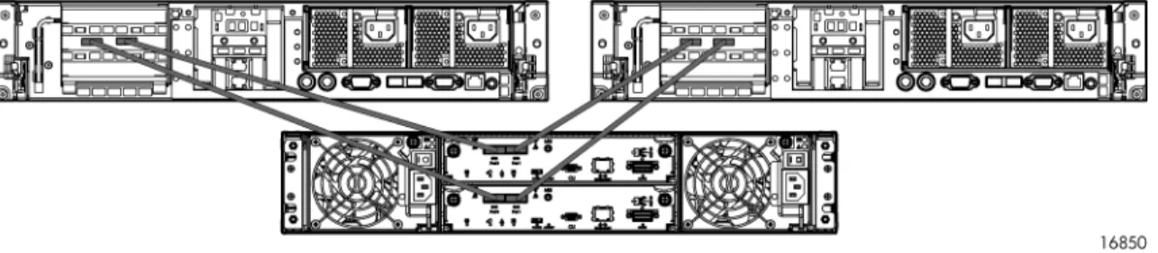
Using the four mini SAS cables provided, connect Server 1 and Server 2 to the MSA as described below.
1. Connect Server 1 HBA Port 0 to MSA Controller B SAS Port 0.
2. Connect Server 1 HBA Port 1 to MSA Controller A SAS Port 0.
3. Connect Server 2 HBA Port 0 to MSA Controller A SAS Port 1.
Figure 5 Cabling diagram: Server 1 and Server 2 connections to the MSA
This cabling configuration ensures that all LUNs remain available in the event of a controller failure.
Connect the storage servers and MSA to the network
After connecting the storage servers to the MSA, make the following power and network connections.
1. Connect the Server 1 NIC 1 connector to the network.
2. Connect the Server 2 NIC 1 connector to the network.
3. Using the crossover cable, connect the Server 1 NIC 2 connector to MSA Controller A NIC 1 connector.
4. Connect the power cords to power outlets.
Power on the storage components and log in
IMPORTANT:
Because the process of configuring the storage servers includes modifying storage server IP addresses, HP recommends that you initially access the storage servers using either the direct connect or iLO 2 remote management method. If you use the Remote Desktop access method to change the storage server IP addresses, you may be disconnected from the storage server and unable to continue the cluster installation process.
1. Power on the storage components in the following order: MSA, Server 1, and then Server 2. When powering on the storage servers for the first time, an HP ProLiant Storage Server installation process is initiated. This process takes approximately 10–15 minutes and requires no user interaction.
NOTE:
If using the direct connect access method, move on to step 3 of “Set static IP addresses for each network connection” on page 15.
2. Locate the iLO 2 Network Settings tag attached to both storage servers and record the default user name, password, and DNS name for each server.
3. From a remote computer, open a standard Web browser and enter the iLO 2 IP address of Server 1.
Set static IP addresses for each network connection
For proper operation of the cluster, each storage server requires both a private heartbeat network connection between the two servers as well as a public facing network connection for file serving purposes. Each NIC adapter must be set with a static IP address that does not register itself with the network DNS server.
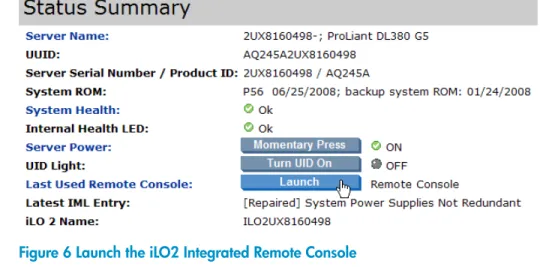
1. On the iLO 2 Status Summary page of Server 1, click Launch to open the iLO 2 Integrated Remote Console.
Figure 6 Launch the iLO2 Integrated Remote Console
2. On the iLO 2 Integrated Remote Console tab, click the button labeled CAD and then click the
Ctrl-Alt-Del menu item.
3. Log in to the Server 1 desktop using the default user name Administrator and password hpinvent.
4. Click Cancel to dismiss the Rapid Startup Wizard and close or minimize the HP Storage Server Management console.
5. On the Server 1 desktop, click Start > Settings > right-click Network Connections and then click
6. Determine which connection is the private connection:
a. Right-click one of the connections and select Status.
b. Select the Support tab.
The connection status of the private connection will indicate Limited or no connectivity; the connection status of the public-facing connection will list network information such as IP Address and Subnet Mask.
Figure 7 Private connection status
Figure 8 Public connection status
c. After identifying the private and public connections, click Close to dismiss the connection status dialog boxes.
7. Right-click the private network connection and select Properties.
10. Select the Use the following IP address radio button and enter the following configuration information:
• IP address: 10.24.3.254 • Subnet mask: 255.255.255.0
Figure 9 Setting the private connection static IP address
11. Click Advanced, select the DNS tab, and uncheck the Register this connection's addresses in DNS
box.
12. Click OK twice and then click Close to dismiss the Connection Properties dialog box. The Server 1 private static IP address is now set.
13. Right-click the public-facing network connection and select Properties.
NOTE:
Do not uncheck any items on the General tab.
15. Select the Use the following IP address radio button and enter the Server 1 public static IP address, Subnet mask, Default gateway, and Preferred DNS server as assigned by your network
administrator. Refer to your network configuration information as identified earlier.
Figure 10 Setting the public connection static IP address
16. Click Advanced, select the DNS tab, and uncheck the Register this connection's addresses in DNS
box.
17. Click OK twice and then click Close to dismiss the Connection Properties dialog box. The Server 1 public static IP address is now set.
18. Repeat the preceding steps on Server 2, setting both the private network static IP address and public-facing static IP address. For the Server 2 private network static IP address settings, enter the following configuration information:
• IP address: 10.24.3.253 • Subnet mask: 255.255.255.0
For the Server 2 public network IP address settings, enter the Server 2 public static IP address, Subnet mask, Default gateway, and Preferred DNS server as assigned by your network administrator.
Join both storage servers to the domain
2. On the Computer Name tab, click Change.
Figure 11 Computer Name tab of System Properties
3. On the Computer Name Changes dialog box, in the Computer name field, enter a unique name for the server.
4. Click the Domain radio button and type the name of the domain on which the cluster will reside and then click OK.
6. Click OK to accept the domain changes.
7. Click Yes to restart the server.
8. Repeat the preceding steps for Server 2.
Log in to the MSA
Use the HP StorageWorks MSA Storage Management Utility to log in to the MSA.
NOTE:
The following procedures can be completed by using the either direct connect, Remote Desktop, or iLO 2 access methods. If using the Remote Desktop connection method, establish the connection using the Server 1 public-facing IP address.
1. Connect to Server 1 using direct connect, iLO 2, or a Remote Desktop connection to the configured Server 1 public-facing IP address.
2. On the Server 1 desktop, select Start > Run, enter http://10.24.3.1, and then click OK.
3. When prompted, click Add to add the MSA to the list of trusted sites that Internet Explorer maintains.
4. Log in to MSA Controller A with the default user name manage and password !manage and click Login.
Set up the Quorum disk
All clusters must have a shared disk called the Quorum disk. The Quorum disk is the shared storage used by the cluster nodes (Server 1 and Server 2) to coordinate the internal cluster state. This physical disk is required for all cluster operations.
Use the HP StorageWorks MSA Storage Management Utility to set up and configure the Quorum disk, a single virtual disk that will be available to both storage servers.
WARNING!
Do not use the Quorum disk to store additional data.
IMPORTANT:
Creating virtual disks can be a lengthy process. Each terabyte of disk space requires approximately two hours of initialization time.
1. In the HP StorageWorks MSA Storage Management Utility, click Manage, then click Create a VDisk.
2. Under Virtual Disk Creation Method, select the Manual Virtual Disk Creation radio button.
4. In the Select Virtual Disk RAID Level list, select a RAID level that provides the best data protection for the number of disks in the enclosure. A minimum of two disks is required.
HP recommends using RAID level 6 for the Quorum disk.
5. Click Create New Virtual Disk.
Figure 13 Enter virtual disk name and RAID Level
6. Under Select Drives to Add to Virtual Disk, check all available drives and then click Continue.
Figure 14 Select drives to add to the virtual disk
7. Under Configure Volumes for Virtual Disk , select the following: • How Many Volumes: 1
• Create Volumes of Equal Size?: No • Present Volumes to All Hosts?: Yes • Automatically Assign LUNs?: Yes
9. After the virtual disk is created, on the Add volumes to virtual disk page, enter a volume size between 512MB and 1024MB and the volume name and then click Add Volumes.
NOTE:
After the cluster is fully set up, you can set up and configure data volumes.
Map the quorum disk volume
After the Quorum disk has been created, add a mapping for the Quorum disk volume.
1. Click Volume Management.
2. Under Volume Management, click Volume Mapping.
3. Under Add or Modify a Mapping for Volume <name>, make the following selections: • In the Host WWN / Nickname list, select All Other Hosts
• In the LUN field, type 1.
• In the Access list, select read-write
• Under Ports, check all check boxes (A0, A1, B0, B1)
4. Click Map It.
Figure 16 Map the quorum disk volume
5. Log off of the HP StorageWorks MSA Storage Management Utility.
Establish the private connection between Server 1 and Server
2
After the Quorum disk has been set up on the MSA, establish the private connection between Server 1 and Server 2 by disconnecting the crossover cable from the MSA Controller A NIC 1 and
reconnecting it to Server 2 NIC 2. This will enable the physical private network heartbeat connection between the two storage servers that is required to set up the cluster. After making this connection, the crossover cable should connect Server 1 NIC 2 to Server 2 NIC 2.
Install the MPIO Driver on both storage servers
1. Open Windows Explorer on Server 1 and navigate to
2. Double-click SETUP.EXE and follow the on-screen instructions
NOTE:
Accept the unsigned driver on the dialog box that appears beneath the MPIO installer dialog box.
3. When prompted at the end of the installation wizard, select Yes, I want to restart my computer now and click Finish.
4. Repeat the preceding steps for MPIO Driver installation on Server 2.
5. When prompted at the end of the installation wizard on Server 2, select No, I want to restart my computer later and click Finish.
6. Shut down Server 2 completely by clicking Start > Shut Down and then clicking OK.
NOTE:
If you are accessing Server 2 through iLO 2, the Integrated Remote Console tab remains visible during shut down. You can use the Integrated Remote Console tab Power button and menu options to power the server back on at a later time during the cluster installation process.
7. After Server 1 restarts, confirm the MPIO installation:
a. Log in to Server 1.
b. On the Server 1 desktop, click Start > Programs > Hewlett-Packard > MSA2000 > MPIO Configuration.
c. At the command prompt, type dev.
d. Confirm that the device is listed, there are 2 paths, and that the policy is RoundRobin.
e. Close the command prompt window.
NOTE:
The default MPIO policy is RoundRobin. Other policies are available and are described in the README.TXT file in the installation path listed above.
Initialize and format the Quorum disk
1. On the Server 1 desktop, right-click My Computer and select Manage.
2. In the console tree, click Disk Management.
NOTE:
3. Right-click the Quorum disk, and then click Initialize Disk.
NOTE:
If the Quorum disk does not appear in the lower-right area of the Computer Management
console, right-click Disk Management and select Rescan Disks.
Figure 17 Initialize the quorum disk
4. In the Initialize Disk dialog box, select the disk to initialize and then click OK. The disk is initialized as a basic disk.
5. In the storage allocation area, right-click and select New Partition.
Figure 18 Create new partition
6. Complete the New Partition Wizard with the following settings: • Primary partition type
• 500 MB partition size • Assign drive letter Z
• Formatted as NTFS
• Name the volume Quorum
• Do not check Quick format or Compression
NOTE:
Before moving on to the next task, ensure that the disk has been completely initialized and formatted. After the disk has been completely initialized and formatted, he storage allocation area should indicate the volume name, size, and state (Healthy, for example).
Run the Cluster Administrator
In clustering terminology, cluster nodes refer to the servers themselves. For the following procedures, Node A represents Server 1 and Node B represents Server 2.
Create the Cluster
1. Click Start > Programs > Administrative Tools >Cluster Administrator. The Open Connection to Cluster dialog box opens.
2. In the Action list, select Create new cluster and then click OK.
4. On the Cluster Name and Domain page, type or select the domain in which the cluster will be created, type a unique name for the cluster, and then click Next.
Figure 19 Set cluster domain and name
5. On the Select Computer page, type or accept the name of Server 1 in the Computer name field, and then click Next.
The Cluster Administrator assesses configuration details of the new cluster. If there are problems with the cluster configuration, click View Log and Details to troubleshoot the issue.
Figure 20 Analyzing cluster configuration
6. After Cluster Administrator successfully analyzes the cluster configuration, click Next.
7. On the IP Address page, type the cluster management IP address as assigned by your network administrator and then click Next.
8. On the Cluster Service Account page, type the cluster service account user name and password as assigned by your network administrator.
Figure 21 Add cluster service account information
9. On the Proposed Cluster Configuration page, review the configuration information and then click
Next.
10. After the cluster creation tasks are completed, click Next and then click Finish. The cluster is created with a single node (Server 1).
11. Power on Server 2 and do not continue until the Server 2 log in prompt appears.
NOTE:
If you are accessing Server 2 through iLO2, click Momentary Press to power on the server.
Figure 22 iLO 2 Integrated Remote Console Virtual Power Button
12. After Server 2 has completely started, return to the Server 1 desktop. On the Cluster Administrator
File menu, click New > Node.
14. On the Select Computer page, type the name of Server 2 in the Computer name field, click Add, and then click Next.
The Cluster Administrator assesses configuration details of the new cluster. If there are problems with the cluster configuration, click View Log and Details to troubleshoot the issue.
NOTE:
If the warning message Cannot find a shareable quorum resource appears on the analysis page, click Back to return to the Select Computer page, click Advanced and select the
Advanced (minimum) configuration, click OK and complete the Add Nodes Wizard.
15. On the Cluster Service Account page, type the cluster service account user name and password as assigned by your network administrator.
16. After the cluster creation tasks are completed, click Next and then click Finish. Server 2 is added to the cluster.
Verify that the active/passive cluster is operational
In order to test cluster functionality, move the cluster group from the active node to the passive node. This prevents clients from accessing cluster resources through that node. In this event, all resources owned by this node fail over to the other node in the server cluster.
1. In the console tree, expand the Groups node and select Cluster Group.
2. Right-click and select Move Group.
3 Setting up an active/active cluster
The following procedures allow you to change an active/passive cluster to a basic active/active cluster with a shared quorum disk, a file share on Server 1, and a file share on Server 2. Before completing the following procedures, set up an active/passive cluster as described in “Setting up an active/passive cluster” on page 13.
Create additional volumes in the MSA
For the purposes of this document, the volumes created in the MSA for the active/active cluster are basic file shares. The example figures are labeled as NFS and CIFS to reflect NFS and CIFS file share resources.
1. Use the HP StorageWorks MSA Storage Management Utility to log in to the MSA (see “Log in to the MSA” on page 20 for login instructions).
2. Click Manage, then click Volume Management.
3. Click Add volume.
4. Under Add Volumes to Virtual Disk, enter a volume size between 512MB and 1024MB, the volume name (for example, NFS for an NFS file share), a LUN number, and then click Add Volume.
Figure 23 Adding a volume in the MSA
5. Repeat the preceding step, adding another volume, such as an additional file share volume. At this point, there should be 3 volumes on the MSA: the quorum disk and the two volumes created for the active/active cluster configuration.
6. Map the two newly-created volumes as described in “Map the quorum disk volume” on page 22.
7. Log off of the HP StorageWorks MSA Storage Management Utility.
2. Initialize and format one of the newly-created disks as described in
“Initialize and format the Quorum disk” on page 23 with the following exceptions: provide a unique name for the volume and assign any available drive letter.
3. Log in to the Server 2 desktop.
4. Initialize and format the remaining newly-created disk as described in
“Initialize and format the Quorum disk” on page 23 with the following exceptions: provide a unique name for the volume and assign any available drive letter.
Add cluster resources
1. Return to the Server 1 desktop.
2. Click Start > Programs > Administrative Tools >Cluster Administrator.
3. Under the first cluster node, right-click the Active Resources folder and select New > Resource. The New Resource Wizard opens.
4. Enter a name, description, select a resource type, and then click Next.
Figure 24 New Resource Wizard
5. On the Possible Owners page, ensure that both cluster nodes are listed in the Possible owners
list and then click Next.
6. On the Dependencies page, move all available resources to the Resource dependencies list and then click Next.
Figure 26 Dependencies page
7. On the final page of the New Resource Wizard, enter the requested resource details, click Finish, and then click OK.
8. Right-click the newly-added resource in Cluster Administrator and then click Bring Online. The resource is added to Server 1 of the cluster and is brought online.
9. Add a second cluster group to Server 2 by right-clicking Groups, selecting New > Group and completing the New Group Wizard.
10. Add the other resource to Server 2 of the cluster by right-clicking the newly-created cluster group, selecting New > Resource and completing the New Resource Wizard.
11. Right-click the newly-added cluster group in Cluster Administrator and then click Bring Online
The cluster is now running in an active/active configuration, with file share resources on both cluster nodes.
Verify that the active/active cluster is operational
In order to test cluster functionality, move one cluster group from one active node to the other active node. This prevents clients from accessing cluster resources through that node. In this event, all resources owned by this node fail over to the other node in the server cluster.
1. In the console tree, expand the Groups node and select Cluster Group.
2. Right-click and select Move Group.
4 Adding components for optimal
availability and redundancy
Configuring the HP ProLiant DL380 G5 High Availability Storage Server for optimal performance, availability, and redundancy requires the purchase of an additional NIC adapter on each storage server and an additional Ethernet crossover cable. HP recommends using the HP NC360T PCI Express Dual Port Gigabit Server Adapter (412648-B21) for optimal active/active performance.
Install the additional equipment and set up the cluster as follows:
1. Install the hardware and make additional connections as described in “Install the hardware” on page 13 and
“Install additional NIC adapters and make additional physical connections” on page 33.
2. Team the private connection NIC adapters and public connection NIC adapters on both storage servers using the HP Network Configuration Utility. For more information on teaming, see the
Teaming adapters section of the HP ProLiant Network Configuration Utility Online Help.
3. Set static IP addresses for each teamed network connection on both storage servers using the configuration information provided in Table 5 on page 11.
4. Create the quorum disk as described in “Set up the Quorum disk” on page 20.
5. Create additional volumes as described in “Create additional volumes in the MSA” on page 29.
6. Initialize and format disks as described in “Initialize and format the disks” on page 29.
7. Add cluster resources as described in “Add cluster resources” on page 30
8. Verify active/active cluster functionality as described in
“Verify that the active/active cluster is operational” on page 32.
Install additional NIC adapters and make additional physical
connections
In addition to setting up the active/passive cluster hardware configuration as described in
“Make the physical connections” on page 13, complete the following additional hardware installation steps. In order to accurately describe the physical connections between the storage components, the ports on the additional NIC adapter are designated as NIC 3 and NIC 4
1. Install the additional NIC adapter in an available expansion slot on Server 1 and Server 2
2. Connect the Server 1 NIC 3 connector to the network.
3. Connect the Server 2 NIC 3 connector to the network.
4. Ensure that the Server 1 NIC 2 is connected to the Server 2 NIC 2 with the an Ethernet crossover cable.