IHE IT Infrastructure
5
Technical Framework
Volume 2b
(ITI TF-2b)
Transactions Part B –
10
Sections 3.29 – 3.64
15
Revision 11 – Final Text
20
September 23, 2014
Please verify you have the most recent version of this document, which is published here. 25
CONTENTS
1 Introduction ... 6
1.1 Overview of the Technical Framework ... 6
30 1.2 Overview of IT Infrastructure Technical Framework Volumes 2a, 2b, 2x, and 3 ... 7
1.3 Audience ... 7
1.4 Relationship to Standards ... 8
1.5 Relationship to Real-world Architectures ... 8
1.6 Comments ... 9
35 1.7 Copyright Permission... 9
2 Conventions ... 10
2.1 The Generic IHE Transaction Model ... 10
2.2 HL7 Profiling Conventions ... 11
2.3 Use of Coded Entities and Coding Schemes... 11
40 3 IHE Transactions ... 12
3.29 Intentionally Left Blank ... 12
3.30Patient Identity Management ... 12
3.30.1 Scope ... 12
3.30.2 Use Case Roles ... 12
45 3.30.3 Referenced Standards ... 13
3.30.4 Message sets and options ... 13
3.30.5 Common HL7 Message Segments ... 14
3.30.6 Interactions ... 32
3.31Patient Encounter Management ... 41
50 3.31.1 Scope ... 41
3.31.2 Use Case Roles ... 41
3.31.3 Referenced Standards ... 41
3.31.4 Definition of the concept “Movement” ... 41
3.31.5 Message sets and options ... 42
55 3.31.6 Common HL7 Message Segments ... 50
3.31.7 Interactions ... 51
3.32Distribute Document Set on Media ... 88
3.32.1 Scope ... 88
3.32.2 Use Case Roles ... 89
60 3.32.3 Referenced Standard ... 89
3.32.4 Interaction Diagram ... 89
3.33Intentionally Left Blank ... 96
3.34 Retrieve Form... 97
3.34.1 Scope ... 97
65 3.34.2 Use Case Roles ... 97
3.34.3 Referenced Standards ... 97
3.34.4 Interaction Diagram ... 98
3.34.5 Protocol Requirements ... 102
3.35 Submit Form ... 105 70
3.35.1 Scope ... 105
3.35.2 Use Case Roles ... 105
3.35.3 Referenced Standards ... 105
3.35.4 Interaction Diagram ... 106
3.35.5 Protocol Requirements ... 107
75 3.35.6 Security Considerations ... 110
3.36 Archive Form ... 111
3.36.1 Scope ... 111
3.36.2 Use Case Roles ... 111
3.36.3 Referenced Standards ... 111
80 3.36.4 Interaction Diagram ... 112
3.36.5 Protocol Requirements ... 113
3.36.6 Security Considerations ... 115
3.37 Retrieve Clarifications ... 116
3.37.1 Scope ... 116
85 3.37.2 Use Case Roles ... 116
3.37.3 Referenced Standards ... 116
3.37.4 Interaction Diagram ... 117
3.37.5 Protocol Requirements ... 120
3.38 Cross Gateway Query ... 123
90 3.38.1 Scope ... 123
3.38.2 Use Case Roles ... 123
3.38.3 Referenced Standard ... 124
3.38.4 Interaction Diagram ... 124
3.38.5 Protocol Requirements ... 128
95 3.39 Cross Gateway Retrieve ... 132
3.39.1 Scope ... 132
3.39.2 Use Case Roles ... 132
3.39.3 Referenced Standard ... 133
3.39.4 Interaction Diagram ... 133
100 3.39.5 Protocol Requirements ... 135
3.40 Provide X-User Assertion ... 140
3.40.1 Scope ... 140
3.40.2 Use Case Roles ... 140
3.40.3 Referenced Standards ... 140
105 3.40.4 Interaction Diagram ... 142
3.41Provide and Register Document Set-b ... 150
3.41.1 Scope ... 151
3.41.2 Use Case Roles ... 151
3.41.3 Referenced Standards ... 152
110 3.41.4 Interaction Diagrams ... 152
3.41.5 Protocol Requirements ... 156
3.41.6 Actor Requirements ... 161
3.41.7 Security Considerations ... 162
3.42Register Document Set-b ... 166 115
3.42.1 Scope ... 166
3.42.2 Use Case Roles ... 166
3.42.3 Referenced Standards ... 167
3.42.4 Interaction Diagram ... 167
3.42.5 Protocol Requirements ... 169
120 3.42.6 Actor Requirements ... 172
3.42.7 Security Considerations ... 172
3.43Retrieve Document Set ... 176
3.43.1 Scope ... 176
3.43.2 Use Case Roles ... 176
125 3.43.3 Referenced Standard ... 177
3.43.4 Interaction Diagram ... 177
3.43.5 Protocol Requirements ... 181
3.43.6 Security Considerations ... 189
3.44 Patient Identity Feed HL7 V3 ... 193
130 3.44.1 Scope ... 193
3.44.2 Use Case Roles ... 193
3.44.3 Referenced Standards ... 193
3.44.4 Interaction Diagrams ... 194
3.44.5 Security Requirements ... 214
135 3.45 PIXV3 Query ... 218
3.45.1 Scope ... 218
3.45.2 Use Case Roles ... 218
3.45.3 Referenced Standards ... 218
3.45.4 Interaction Diagrams ... 219
140 3.45.5 Security Requirements ... 232
3.46 PIXV3 Update Notification... 236
3.46.1 Scope ... 236
3.46.2 Use Case Roles ... 236
3.46.3 Referenced Standards ... 236
145 3.46.4 Interaction Diagrams ... 237
3.46.5 Security Requirements ... 244
3.47 Patient Demographics Query HL7 V3 ... 246
3.47.1 Scope ... 246
3.47.2 Use Case Roles ... 246
150 3.47.3 Referenced Standards ... 247
3.47.4 Interaction Diagrams ... 248
3.47.5 Security Requirements ... 269
3.48 Retrieve Value Set... 272
3.48.1 Scope ... 272
155 3.48.2 Use case roles ... 273
3.48.3 Referenced Standards ... 273
3.48.4 Interaction Diagram ... 273
3.48.5 Protocol Requirements ... 276
3.48.6 Security Requirements ... 280 160
3.49Convey Printed Referral Request... 283
3.50Request Referral... 283
3.51 Multi-Patient Stored Query ... 283
3.51.1 Scope ... 283
3.51.2 Use Case Roles ... 284
165 3.51.3 Referenced Standard ... 284
3.51.4 Interaction Diagram ... 284
3.51.5 Security Considerations ... 290
3.55 Cross Gateway Patient Discovery ... 293
3.55.1 Scope ... 293
170 3.55.2 Use Case Roles ... 294
3.55.3 Referenced Standard ... 295
3.55.4 Interaction Diagram ... 295
3.55.5 Security Considerations ... 318
3.55.6 Protocol Requirements ... 321
175 3.60 Retrieve Multiple Value Sets ... 327
3.60.1 Scope ... 327
3.60.2 Use case roles ... 327
3.60.3 Referenced Standards ... 327
3.60.4 Interaction Diagram ... 328
180 3.60.5 Protocol Requirements ... 332
3.60.6 Security Requirements ... 335
3.61 Register On-Demand Document Entry ... 335
3.61.1 Scope ... 335
3.61.2 Use Case Roles ... 336
185 3.61.3 Referenced Standard ... 336
3.61.4 Interaction Diagram ... 337
3.61.5 Protocol Requirements ... 340
3.61.7 Security Considerations ... 341
3.62 Reserved for Delete Document Set ... 344
190 3.63 Reserved for Cross Gateway Fetch ... 344
1 Introduction
195
Integrating the Healthcare Enterprise (IHE) is an initiative designed to stimulate the integration of the information systems that support modern healthcare institutions. Its fundamental objective is to ensure that in the care of patients all required information for medical decisions is both correct and available to healthcare professionals. The IHE initiative is both a process and a forum for encouraging integration efforts. It defines a technical framework for the implementation of 200
established messaging standards to achieve specific clinical goals. It includes a rigorous testing process for the implementation of this framework. And it organizes educational sessions and exhibits at major meetings of medical professionals to demonstrate the benefits of this framework and encourage its adoption by industry and users.
The approach employed in the IHE initiative is to support the use of existing standards, e.g., 205
HL7, ASTM, DICOM, ISO, IETF, OASIS and others as appropriate, rather than to define new standards. IHE profiles further constrain configuration choices where necessary in these standards to ensure that they can be used in their respective domains in an integrated manner between different actors. When clarifications or extensions to existing standards are necessary, IHE refers recommendations to the relevant standards bodies.
210
This initiative has numerous sponsors and supporting organizations in different medical specialty domains and geographical regions. In North America the primary sponsors are the Healthcare Information and Management Systems Society (HIMSS) and the Radiological Society of North America (RSNA). IHE Canada has also been formed. IHE Europe (IHE-EUR) is supported by a large coalition of organizations including the European Association of Radiology (EAR) and 215
European Congress of Radiologists (ECR), the Coordination Committee of the Radiological and Electromedical Industries (COCIR), Deutsche Röntgengesellschaft (DRG), the EuroPACS Association, Groupement pour la Modernisation du Système d'Information Hospitalier (GMSIH), Société Francaise de Radiologie (SFR), Società Italiana di Radiologia Medica (SIRM), and the European Institute for health Records (EuroRec). In Japan IHE-J is sponsored 220
by the Ministry of Economy, Trade, and Industry (METI); the Ministry of Health, Labor, and Welfare; and MEDIS-DC; cooperating organizations include the Japan Industries Association of Radiological Systems (JIRA), the Japan Association of Healthcare Information Systems Industry (JAHIS), Japan Radiological Society (JRS), Japan Society of Radiological Technology (JSRT), and the Japan Association of Medical Informatics (JAMI). Other organizations representing 225
healthcare professionals are invited to join in the expansion of the IHE process across disciplinary and geographic boundaries.
1.1 Overview of the Technical Framework
This document, the IHE IT Infrastructure Technical Framework (ITI TF), defines specific implementations of established standards to achieve integration goals that promote appropriate 230
sharing of medical information to support optimal patient care. It is expanded annually, after a period of public review, and maintained regularly through the identification and correction of errata. The current version, Rev. 11.0 for Final Text, specifies the IHE transactions defined and implemented as of September 2014. The latest version of the document is always available via the Internet at http://ihe.net/Technical_Frameworks.
The IHE IT Infrastructure Technical Framework identifies a subset of the functional components of the healthcare enterprise, called IHE actors, and specifies their interactions in terms of a set of coordinated, standards-based transactions. It describes this body of transactions in progressively greater depth. Volume 1 (ITI TF-1) provides a high-level view of IHE functionality, showing the transactions organized into functional units called integration profiles that highlight their
240
capacity to address specific IT Infrastructure requirements.
Volumes 2a, 2b, and 2x of the IT Infrastructure Technical Framework provides detailed technical descriptions of each IHE transaction used in the IT Infrastructure Integration Profiles. Volume 3 contains content specification and specifications used by multiple transactions. These volumes are consistent and can be used in conjunction with the Integration Profiles of other IHE domains. 245
The other domains within the IHE initiative also produce Technical Frameworks within their respective areas that together form the IHE Technical Framework. For example, the following IHE Technical Framework(s) are some of those which are available:
• IHE IT Infrastructure Technical Framework • IHE Cardiology Technical Framework 250
• IHE Laboratory Technical Framework
• IHE Patient Care Coordination Technical Framework • IHE Radiology Technical Framework
Where applicable, references are made to other technical frameworks. For the conventions on referencing other frameworks, see ITI TF-1: 1.6.3.
255
1.2 Overview of IT Infrastructure Technical Framework Volumes 2a,
2b, 2x, and 3
The remainder of Section 1 further describes the general nature, purpose and function of the Technical Framework. Section 2 presents the conventions used in this volume to define IHE transactions.
260
Section 3 defines transactions in detail, specifying the roles for each Actor, the standards employed, the information exchanged, and in some cases, implementation options for the transaction. Section 3 is divided into two parts:
• Volume 2a: Sections 3.1 - 3.28 corresponding to transactions [ITI-1] through [ITI-28]. • Volume 2b: Sections 3.29 - 3.64 corresponding to transactions [ITI-29] through [ITI-64]. 265
Volume 2x contains all appendices providing technical details associated with the transactions. Volume 3, Section 4 contains specifications that are used by multiple transactions.
Volume 3, Section 5 contains Content Specifications.
1.3 Audience
The intended audience of this document is: 270
• IT departments of healthcare institutions
• Technical staff of vendors planning to participate in the IHE initiative • Experts involved in standards development
• Those interested in integrating healthcare information systems and workflows
1.4 Relationship to Standards
275
The IHE Technical Framework identifies functional components of a distributed healthcare environment (referred to as IHE actors), solely from the point of view of their interactions in the healthcare enterprise. At its current level of development, it defines a coordinated set of
transactions based on ASTM, DICOM, HL7, IETF, ISO, OASIS and W3C standards. As the scope of the IHE initiative expands, transactions based on other standards may be included as 280
required.
In some cases, IHE recommends selection of specific options supported by these standards; however, IHE does not introduce technical choices that contradict conformance to these
standards. If errors in or extensions to existing standards are identified, IHE’s policy is to report them to the appropriate standards bodies for resolution within their conformance and standards 285
evolution strategy.
IHE is therefore an implementation framework, not a standard. Conformance claims for products must still be made in direct reference to specific standards. In addition, vendors who have
implemented IHE integration capabilities in their products may publish IHE Integration Statements to communicate their products’ capabilities. Vendors publishing IHE Integration 290
Statements accept full responsibility for their content. By comparing the IHE Integration Statements from different products, a user familiar with the IHE concepts of actors and integration profiles can determine the level of integration between them. See ITI TF-2x: Appendix C for the format of IHE Integration Statements.
1.5 Relationship to Real-world Architectures
295
The IHE actors and transactions described in the IHE Technical Framework are abstractions of the real-world healthcare information system environment. While some of the transactions are traditionally performed by specific product categories (e.g., HIS, Clinical Data Repository, Radiology Information Systems, Clinical Information Systems or Cardiology Information
Systems), the IHE Technical Framework intentionally avoids associating functions or actors with 300
such product categories. For each Actor, the IHE Technical Framework defines only those functions associated with integrating information systems. The IHE definition of an Actor should therefore not be taken as the complete definition of any product that might implement it, nor should the framework itself be taken to comprehensively describe the architecture of a healthcare information system.
305
The reason for defining actors and transactions is to provide a basis for defining the interactions among functional components of the healthcare information system environment. In situations where a single physical product implements multiple functions, only the interfaces between the product and external functions in the environment are considered to be significant by the IHE
initiative. Therefore, the IHE initiative takes no position as to the relative merits of an integrated 310
environment based on a single, all-encompassing information system versus one based on multiple systems that together achieve the same end. IHE demonstrations emphasize the integration of multiple vendors’ systems based on the IHE Technical Framework.
1.6 Comments
IHE International welcomes comments on this document and the IHE initiative. They can be 315
submitted using the Web-based comment form at http://www.ihe.net/ITI_Public_Comments or by sending an email to the co-chairs and secretary of the IT Infrastructure domain committees at
1.7 Copyright Permission
Health Level Seven, Inc., has granted permission to the IHE to reproduce tables from the HL7 320
standard. The HL7 tables in this document are copyrighted by Health Level Seven, Inc. All rights reserved. Material drawn from these documents is credited where used.
2 Conventions
This document has adopted the following conventions for representing the framework concepts and specifying how the standards upon which the IHE IT Infrastructure Technical Framework is 325
based should be applied.
2.1 The Generic IHE Transaction Model
Transaction descriptions are provided in Section 3. In each transaction description, the actors, the roles they play, and the transactions between them are presented as use cases.
The generic IHE transaction description includes the following components: 330
Scope: a brief description of the transaction.
Use case roles: textual definitions of the actors and their roles, with a simple diagram relating them, e.g.,:
Actor Actor
Transaction
Referenced Standards: the standards (stating the specific parts, chapters or sections thereof) 335
to be used for the transaction.
Interaction Diagram: a graphical depiction of the actors and messages that support the transaction, with related processing within an Actor shown as a rectangle and time progressing downward, similar to:
Actor Actor Actor
MSG1
MSG2
MSG3
The interaction diagrams used in the IHE IT Infrastructure Technical Framework are modeled after those described in Grady Booch, James Rumbaugh, and Ivar Jacobson, The Unified Modeling Language User Guide, ISBN 0-201-57168-4. Simple acknowledgment messages are often omitted from the diagrams for brevity. One or more messages may be 345
required to satisfy a transaction. Each message is represented as an arrow starting from the Actor initiating the message.
Message definitions: descriptions of each message involved in the transaction, the events that trigger the message, its semantics, and the actions that the message triggers in the
receiver. 350
2.2 HL7 Profiling Conventions
See ITI TF-2x: Appendix C for the HL7 profiling conventions as well as the networking implementation guidelines.
2.3 Use of Coded Entities and Coding Schemes
IHE does not produce, maintain or otherwise specify a coding scheme or other resource for 355
controlled terminology (coded entities). Where applicable, coding schemes required by the HL7 and DICOM standards take precedence. In the cases where such resources are not explicitly identified by standards, implementations may utilize any resource (including proprietary or local) provided any licensing/copyright requirements are satisfied.
3 IHE Transactions
360
This section defines each IHE transaction in detail, specifying the standards used, the
information transferred, and the conditions under which the transaction is required or optional.
3.29 Intentionally Left Blank
3.30 Patient Identity Management
This section corresponds to Transaction ITI-30, “Patient Identity Management” of the IHE IT 365
Infrastructure Technical Framework. Transaction ITI-30 is used by the actors Patient Demographics Supplier and Patient Demographics Consumer.
3.30.1 Scope
This transaction transmits patient demographics in a patient identification domain (i.e., patient identifiers assigned by the same assigning authority).
370
The term “patient demographics” is intended to convey the patient identification and full identity and also information on persons related to this patient, such as primary caregiver, family doctor, guarantor, next of kin.
The transaction contains events for creating, updating, merging, linking and unlinking patients. It enables the sending system to qualify the reliability of a patient identity, and the type of 375
identity used (official name, alias for VIP, unknown patient).
The transaction can be used in acute care settings for both inpatients (i.e., those who are assigned a bed at the facility) and outpatients (i.e., those who are not assigned a bed at the facility).
The transaction can also be used in a pure ambulatory environment.
3.30.2 Use Case Roles
380
Patient Identity
Management
Patient
Demographics
Supplier
Patient
Demographics
Consumer
Patient
Identity
Source
Patient Identitifier
Cross-Reference
Manager
Actor: Patient Demographics Supplier
Role: Adds and modifies patient demographics.
Role: Receives patient demographics. 385
Actor: Patient Identity Source
Role: Adds and modifies patient demographics.
Actor: Patient Identifier Cross-Reference Manager
Role: Receives patient demographics.
3.30.3 Referenced Standards
390
HL7 2.5 Chapters 2, 3, 6, 15
3.30.4 Message sets and options
Transaction ITI-30 supports two options, “Merge” and “Link/Unlink”, in order to accommodate the various methods used by healthcare organizations to reconcile duplicated identities.
Any Patient Demographics Supplier or Patient Demographics Consumer Actor SHALL support 395
at least one of the two options “Merge” and “Link/Unlink” or both, according to the IHE national extensions of this transaction. Any implementation framework will mandate both actors to
support the same option. See 3.30.4.1 and 3.30.4.2.
Patient Identity Source and Patient Identity Cross-Reference Manager actors may support the Pediatric Demographics Option. See 3.30.4.3.
400
3.30.4.1 Required message subset with option “Merge”
Event Trigger Message Static definition
Create new patient A28 ADT^A28^ADT_A05
Update patient information A31 ADT^A31^ADT_A05
Change Patient Identifier List A47 ADT^A47^ADT_A30
Merge two patients A40 ADT^A40^ADT_A39
3.30.4.2 Required message subset with option “Link/Unlink”
405
Event Trigger Message Static definition
Create new patient A28 ADT^A28^ADT_A05
Update patient information A31 ADT^A31^ADT_A05
Change Patient Identifier List A47 ADT^A47^ADT_A30
Link Patient Information A24 ADT^A24^ADT_A24
3.30.4.3 Optionality of Pediatric Demographics Fields
The Pediatric Demographics Option does not require Patient Identity Source Actors to include any attributes not already required by the corresponding HL7 message (as is described in the following sections). This minimal set of requirements enables inclusion of the largest range of Patient Identity Source Actor systems.
410
The Pediatric Demographics Option does place additional requirements on the Patient Identifier Cross-reference Manager Actor, requiring them to accept and consider in matching* a set of HL7 attributes beyond what is required by standard PIX. See Table 3.30.4.3-1 for a description of these additional requirements. For example, we would expect that two patients with all furnished data elements identical except the First Name (e.g., “Maria” vs. “Marina”), and consecutive Birth 415
Order values would not be automatically linked or merged by the Patient Identifier Cross-Reference Manager.
3.30.4.4 Acknowledgement Support
An actor that claims support for the Acknowledgement Support Option shall be capable of using the enhanced acknowledgement mode as defined in the HL7 v2.x standard. See HL7 Volume 2C, 420
Section C.2.3 for further details.
3.30.4.5 Ambulatory Patient Data
If the Patient Demographics Supplier supports the Ambulatory Patient Data Option, it SHALL supply the patient address in field PID-11 for ambulatory patients whenever this address is known.
425
3.30.5 Common HL7 Message Segments
This section describes the common HL7 message segments used in Transaction 30. Each table represents a segment. Fields for which a precise usage description is needed,
particularly those having usage C (conditional), are commented on below the table. The optional fields are usually not commented on.
430
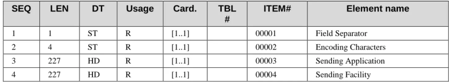
3.30.5.1 MSH - Message Header Segment
Standard Reference: HL7 Version 2.5, Chapter 2 (Section 2.15, “Message control”)
This segment defines the intent, supplier, destination, and some specifics of the syntax of the message. It also uniquely identifies the message itself and dates its production.
435
Table 3.30-1: MSH - Message Header
SEQ LEN DT Usage Card. TBL #
ITEM# Element name
1 1 ST R [1..1] 00001 Field Separator
2 4 ST R [1..1] 00002 Encoding Characters
3 227 HD R [1..1] 00003 Sending Application
SEQ LEN DT Usage Card. TBL #
ITEM# Element name
5 227 HD R [1..1] 00005 Receiving Application
6 227 HD R [1..1] 00006 Receiving Facility
7 26 TS R [1..1] 00007 Date/Time of Message
8 40 ST X [0..0] 00008 Security
9 15 MSG R [1..1] 00009 Message Type
10 20 ST R [1..1] 00010 Message Control Id
11 3 PT R [1..1] 00011 Processing Id
12 60 VID R [1..1] 00012 Version ID
13 15 NM O [0..1] 00013 Sequence Number
14 180 ST X [0..0] 00014 Continuation Pointer
15 2 ID O [0..1] 0155 00015 Accept Acknowledgement Type
16 2 ID O [0..1] 0155 00016 Application Acknowledgement Type
17 3 ID RE [1..1] 0399 00017 Country Code
18 16 ID C [0..1] 0211 00692 Character Set
19 250 CE RE [0..1] 00693 Principal Language of Message
20 20 ID X [0..0] 0356 01317 Alternate Character Set Handling
Scheme
21 427 EI RE [0..*] 01598 Message Profile Identifier
MSH-1 Field Separator, required: This Technical Framework requires that applications support as the recommended value specified in the HL7 standard, which is | (ASCII 124). See volume 2x: Appendix C.
440
MSH-2 Encoding Characters, required: This field contains the four characters in the following order: the component separator, repetition separator, escape character, and subcomponent
separator. This Technical Framework requires that applications support the recommended values for encoding characters as specified in the HL7 standard. The values are ^~\& (ASCII 94, 126, 92, and 38, respectively). See ITI TF-2x: Appendix C.
445
MSH-3 Sending Application (HD) and MSH-5 Receiving Application (HD), required. See the constrainable profile definition of data type HD.
MSH-4 Sending Facility (HD) and MSH-6 Receiving Facility (HD), required. See the constrainable profile definition of data type HD.
MSH-9 Message Type (MSG), required:
450
Components: <Message Code (ID)> ^ <Trigger Event (ID)> ^ <Message Structure (ID)> Definition: This field contains the message type, trigger event, and the message structure ID for the message. All three components are required.
MSH-10 Message Control Id (ST), required:
Definition: This field contains a number or other identifier that uniquely identifies the message in 455
identifier by the sending system. The receiving system will echo this ID back to the sending system in the Message Acknowledgment segment (MSA). The combination of this identifier and the name of the sending application (MSH-3) should be unique across the healthcare enterprise.
MSH-12 Version ID (VID), required: 460
Components: <Version ID (ID)> ^ <Internationalization Code (CE)> ^ <International Version ID (CE)>
Definition: This field is matched by the receiving system to its own version to be sure the message will be interpreted correctly.
The first component SHALL be populated with the value "2.5" representing HL7 Version 2.5. 465
MSH-15 Accept Acknowledgment Type (ID), optional.
As a minimal requirement for all actors, the Original Acknowledgement Mode shall be supported, in which case this field of the message will remain empty.
If an actor declares the “Acknowledgement Support” Option, it shall be able to use Enhanced Acknowledgement Mode.
470
MSH-16 Application Acknowledgment Type (ID), optional.
As a minimal requirement for all actors, the Original Acknowledgement Mode shall be supported, in which case this field of the message will remain empty.
If an actor declares the “Acknowledgement Support” Option, it shall be able to use Enhanced Acknowledgement Mode.
475
MSH-17 Country Code (ID), required if available.
Definition: This field contains the country of origin for the message. The values to be used are those of ISO 3166, using the 3-character alphabetic form. Refer to HL7 Table 0399 - Country code.
Examples of valid values: 480
JPN = Japan, USA = United States, GBR = United Kingdom, ITA = Italy, FRA = France, NLD = Netherlands.
MSH-18 Character Set (ID), conditional.
Definition: This field contains the character set for the entire message. Refer to HL7 Table 0211 - Alternate character sets for valid values.
485
Examples of valid values:
ASCII: The printable 7-bit ASCII character set.
8859/1: The printable characters from the ISO 8859/1 Character set used by Western Europe. This character set can still be used, but 8859/15 should be used by preference. This character set is the forward-compatible version of 8859/1 and includes new characters such as the Euro 490
ISO IR87: Code for the Japanese Graphic Character set for information interchange (JIS X 0208-1990).
UNICODE UTF-8: UCS Transformation Format, 8-bit form.
Condition predicate: This field shall only be valued if the message uses a character set other 495
than the 7-bit ASCII character set. Though the field is repeatable in HL7, IHE authorizes only one occurrence (i.e., one character set). The character set specified in this field is used for the encoding of all of the characters within the message.
MSH-19 Principal Language of Message (CE), required if available. Coded from ISO 639. Examples: DE = German, EN = English, ES=Spanish, JA = Japanese, FR = French, NL = Dutch, 500
IT = Italian
MSH-20 Alternate Character Set Handling Scheme (ID), not supported: Character set switching is not allowed here.
MSH-21 Message Profile Identifier (EI), required if available.
This field shall be valued in the messages for which a Message Profile has been officially 505
registered with HL7, and is recommended to be valued for all messages in accordance with IHE Technical Framework transactions. See volume 2x: Appendix C.
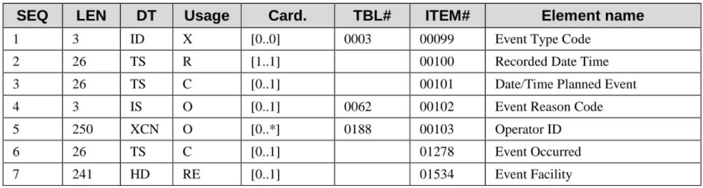
3.30.5.2 EVN – Event Type Segment
Standard Reference: HL7 Version 2.5, Chapter 3, Section 3.4.1
This segment is used to provide generic properties of the trigger event. 510
Table 3.30-2: EVN – Event Type segment
SEQ LEN DT Usage Card. TBL# ITEM# Element name
1 3 ID X [0..0] 0003 00099 Event Type Code
2 26 TS R [1..1] 00100 Recorded Date Time
3 26 TS C [0..1] 00101 Date/Time Planned Event
4 3 IS O [0..1] 0062 00102 Event Reason Code
5 250 XCN O [0..*] 0188 00103 Operator ID
6 26 TS C [0..1] 01278 Event Occurred
7 241 HD RE [0..1] 01534 Event Facility
EVN-1 Event Type Code (ID): Not supported (deprecated in HL7 2.5). The Event Type Code is given in MSH-9 of segment MSH.
515
EVN-2 Recorded Date Time (TS): Required. Date/time when the event was recorded.
EVN-3 Date/Time Planned Event (TS): Conditional. Date/time when the event was planned. Condition predicate:
• This field shall be populated in events “Pending Transfer” (A15) and “Cancel Pending Transfer” (A26), which are supported by transaction ITI-31.
520
• The update of a pending transfer uses message A08 and leaves this field empty. The update of the planned date/time of the transfer is only possible through the ZBE segment in message Z99, when using the option “Historic Movement Management” of transaction ITI-31.
• Other planned events of transaction ITI-31, such as “Pending Admit”, “Pending 525
Discharge” and the cancels thereof, use a specific field of segment PV2 to give the date/time of the planned event. For consistency of use, IHE recommends that the content of the specific field of PV2 be also copied to EVN-3.
National extensions of this transaction may extend the condition above.
EVN-6 Event Occurred (TS): Conditional. This field contains the date/time that the event really 530
occurred.
Condition predicate:
• This field shall not be populated in messages communicating pending events and their cancellations.
• In messages communicating effective events (inserts and updates), this field shall be 535
populated with the real date/time of the notified event.
• In messages communicating cancellations, this field shall be populated with the date/time that was sent in the message that originally communicated the event being cancelled.
EVN-7 Event Facility (HD): Required if known to the sender. This field identifies the actual facility where the event occurred as distinct from the sending facility (MSH-4).
540
3.30.5.3 PID - Patient Identification segment
Standard Reference: HL7 Version 2.5, Chapter 3 (Section 3.4.2)
The PID segment is used by all applications as the primary means of communicating patient identification information. This segment contains permanent patient identifying and demographic information that, for the most part, is not likely to change frequently.
545
Table 3.30-3: PID - Patient Identification segment
SEQ LEN DT Usage Card. TBL# ITEM# Element name
1 4 SI O [0..1] 00104 Set ID - PID
2 20 CX X [0..0] 00105 Patient ID
3 250 CX R [1..*] 00106 Patient Identifier List
4 20 CX X [0..0] 00107 Alternate Patient ID - PID
5 250 XPN R [1..*] 00108 Patient Name
6 250 XPN O
(Note 1)
SEQ LEN DT Usage Card. TBL# ITEM# Element name
7 26 TS CE
(Note 1)
[0..1] 00110 Date/Time of Birth
8 1 IS CE
(Note 1)
[1..1] 0001 00111 Administrative Sex
9 250 XPN X [0..1] 00112 Patient Alias
10 250 CE O [0..1] 0005 00113 Race
11 250 XAD CE
(Note 1)
[0..*] 00114 Patient Address
12 4 IS X [0..1] 0289 00115 County Code
13 250 XTN O
(Note 1)
[0..*] 00116 Phone Number - Home
14 250 XTN O [0..*] 00117 Phone Number - Business
15 250 CE O [0..1] 0296 00118 Primary Language
16 250 CE O [0..1] 0002 00119 Marital Status
17 250 CE O [0..1] 0006 00120 Religion
18 250 CX C [0..1] 00121 Patient Account Number
19 16 ST X [0..1] 00122 SSN Number - Patient
20 25 DLN X [0..1] 00123 Driver's License Number - Patient
21 250 CX O [0..*] 00124 Mother's Identifier
22 250 CE O [0..1] 0189 00125 Ethnic Group
23 250 ST O [0..1] 00126 Birth Place
24 1 ID O
(Note 1)
[0..1] 0136 00127 Multiple Birth Indicator
25 2 NM O
(Note 1)
[0..1] 00128 Birth Order
26 250 CE O [0..1] 0171 00129 Citizenship
27 250 CE O [0..1] 0172 00130 Veterans Military Status
28 250 CE X [0..0] 0212 00739 Nationality
29 26 TS CE [0..1] 00740 Patient Death Date and Time
30 1 ID C [0..1] 0136 00741 Patient Death Indicator
31 1 ID CE [0..1] 0136 01535 Identity Unknown Indicator
32 20 IS CE [0..*] 0445 01536 Identity Reliability Code
33 26 TS CE
(Note 1)
[0..1] 01537 Last Update Date/Time
34 241 HD O
(Note 1)
[0..1] 01538 Last Update Facility
35 250 CE CE [0..1] 0446 01539 Species Code
36 250 CE C [0..1] 0447 01540 Breed Code
37 80 ST O [0..1] 01541 Strain
38 250 CE O [0..2] 01542 Production Class Code
Note 1: If the Pediatric Demographics Option is supported, this element in the table above shall be R2 for the Patient Identifier Cross-Reference Manager.
550
In accord with the HL7 Version 2.5 usage of this segment, fields PID-2 (Patient ID), PID-4 (Alternate Patient ID), PID-19 (SSN patient number) and PID-20 (Driver’s license number) are superseded by field PID-3, as shown below; field PID-28 (Nationality) is superseded by field PID-26 (Citizenship).
PID-3 – Patient Identifier List (CX), required. This field contains a list of identifiers (one or 555
more) used by the healthcare facility to uniquely identify a patient.
As shown in the constrained profile definition of data type CX at the end of this supplement, subfields CX-1 “ID number”, CX-4 “Assigning authority”, and CX-5 “Identifier Type Code” are required for each identifier.
This field may be populated with various identifiers assigned to the patient by various assigning 560
authorities.
The authorized values for subfield CX-5 “Identifier Type Code” are given in HL7 Table 0203 (HL7 Version 2.5, Chapter 2A, Section 2A.14.5).
Values commonly used for Identifier Type Code in the context of PID-3 are as follows: BC Bank card number. Assigning authority is the bank.
565
BR Birth Certificate number. Assigning authority is the birth state or national government that issues the Birth Certificate.
DL Driver’s license number. Assigning authority is the state
NH National Health Plan Identifier. Assigning authority at the national level. PE Living Subject Enterprise Number. Assigning authority is the enterprise. 570
PI Patient Internal Identifier assigned by the healthcare organization. PPN Passport number.
PRC Permanent Resident Card Number SS Social Security Number.
575
PID-5 – Patient Name (XPN), required. This field contains one or more names for the patient. At least one name must be provided, with at least the first subfield “Family Name” valued. See the constrained profile definition of data type XPN.
PID-6 – Mother’s Maiden Name (XPN), conditional:
Condition predicate: 580
This field is required if known for the Pediatrics Demographic Option. It serves to help link records when other demographic data and search criteria are not exactly the same.
Condition predicate:
• This field is required if available (i.e., known to the sender) in the following messages: 585
Creation of a new patient (A28 in ITI-30), inpatient admitted (A01 in ITI-31), registration of an outpatient (A04 in ITI-31), update patient demographics (A31 in ITI-30), update patient demographics in the context of an encounter (A08 in ITI-31).
• In all other messages, it is optional.
• If the exact date of birth is not known, it can be truncated to the year of birth (e.g., 1954) 590
or to the year and month of birth (e.g., 195411).
PID-8 – Administrative Sex (IS), conditional. Condition predicate:
• This field is required if available in the following messages: Creation of a new patient (A28 in ITI-30), inpatient admitted (A01 in ITI-31), registration of an outpatient (A04 in 595
ITI-31), update patient demographics (A31 in ITI-30). • In all other messages, it is optional.
• The authorized values are these, taken from HL7 User-defined Table 0001:
User-defined Table 0001: Administrative Sex
600
Value Description Comment
F Female
M Male
O Other
U Unknown
A Ambiguous
N Not applicable
PID-10 – Race (CE), optional: The patient race is information of critical medical importance in practices such as imaging. Therefore this information shall be present if known, except where prohibited. For example, France prohibits inclusion of Patient Race.
PID-11 – Patient Address (XAD), conditional: 605
Condition predicate:
• This field is required if available (if known to the sender) in the following messages: Creation of a new patient (A28 in ITI-30), inpatient admitted (A01 in ITI-31), registration of an outpatient (A04 in ITI-31), update patient demographics (A31 in ITI-30).
• In all other messages, it is optional. 610
PID-13 – Home Phone Number (XTN), conditional.
This field is required if known for the Pediatrics Demographic Option. It serves to help locate records when other demographic data and search criteria are not exactly the same.
PID-18 – Patient Account Number (CX): Conditional. 615
HL7 Definition: This field contains the patient account number assigned by accounting to which all charges, payments, etc., are recorded. It is used to identify the patient’s account.
Relationship to encounter: A patient account can span more than one enterprise encounter. Condition predicate: At least one of the fields PID-18 “Patient Account Number” or PV1-19 “Visit Number” shall be valued in the messages of transaction ITI-31 that use the PV1 segment. 620
Additional requirements for the presence of value in these fields may be documented in national extensions of this transaction.
PID-24 – Multiple Birth Indicator (ID), conditional. Condition predicate:
This field is required if known for the Pediatrics Demographic Option. It serves to help avoid 625
linking records for twins, which are often nearly identical.
PID-25 – Birth Order (NM), conditional. Condition predicate:
This field is required if known for the Pediatrics Demographic Option. It serves to help avoid linking records for twins, which are often nearly identical.
630
PID-29 – Patient Death Date and Time (TS), conditional: Condition predicate:
• This field is required in the Patient Discharge message of transaction ITI-31,if the
encounter is terminated by the patient’s death and the death date is known. It provides the date/time of the patient’s death.
635
• In all other Patient Discharge messages, it shall not be populated.
PID-30 – Patient Death Indicator (ID), conditional: Condition predicate:
• This field is required to be populated with value “Y” in the Patient Discharge message of transaction ITI-31 when the encounter is terminated by the patient’s death.
640
• Otherwise it is optional.
PID-31 – Identity Unknown Indicator (ID), conditional: Condition predicate:
• This field is required if available (i.e., known to the sender) in the following messages: Creation of a new patient (A28 in ITI-30), inpatient admitted (A01 in ITI-31), registration 645
of an outpatient (A04 in ITI-31), update patient demographics (A31 in ITI-30) , update patient demographics in the context of an encounter (A08 in ITI-31).
• In all other messages, it is optional.
The possible values are “Y”, and “N” which is the default.
The value “Y” means that the patient identity is unknown. In this case the field PID-3 shall 650
contain one single patient identifier, which is a temporary identifier, and the field PID-32 will contain the value “AL” indicating that the patient name is an alias.
PID-32 – Identity Reliability Code (IS), conditional: Condition predicate:
• This field is required if available (i.e., known to the sender) in the following messages: 655
Creation of a new patient (A28 in ITI-30), inpatient admitted (A01 in ITI-31), registration of an outpatient (A04 in ITI-31), update patient demographics (A31 in ITI-30) , update patient demographics in the context of an encounter (A08 in ITI-31).
• In all other messages, it is optional.
The field is repeatable. The possible values are taken from HL7 user-defined Table 0445: 660
User-defined Table 0445: Identity Reliability Code
Value Description Comment (added by IHE for this profile)
AL Patient/Person Name is an Alias Used in case of an unidentified patient (e.g., trauma case)
PID-33 – Last Update Date/Time (TS), conditional: Condition predicate:
665
• This field is required if available (i.e., known to the sender) in the following messages: Creation of a new patient (A28 in ITI-30), inpatient admitted (A01 in ITI-31), registration of an outpatient (A04 in ITI-31), update patient demographics (A31 in ITI-30), update patient demographics in the context of an encounter (A08 in ITI-31).
• In the cases of messages A08 and A31, the content of this field is equal to the value in 670
EVN-6-event occurred.
Note: This field is required if known for the Pediatrics Demographic Option. The condition predicate above satisfies this requirement. It serves to help avoid linking records for twins, which are often nearly identical. It is used in conjunction with PID-34.
PID-34 – Last Update Facility (HD), conditional. 675
Condition predicate:
This field is required if known for the Pediatrics Demographic Option. It serves to help avoid linking records for twins, whose records are often nearly identical, when used in conjunction with PID-33.
PID-35 – Species Code (CE) and PID-36 – Breed Code (CE), conditional: 680
• Required if known to the sender, when the patient is a non-human living subject, in the following messages: Creation of a new patient (A28 in ITI-30), inpatient admitted (A01 in ITI-31), registration of an outpatient (A04 in ITI-31), update patient demographics (A31 in 30), update patient demographics in the context of an encounter (A08 in ITI-685
31).
3.30.5.4 PV1 - Patient Visit segment
Standard Reference: HL7 Version 2.5, Chapter 3 (Section 3.4.3)
The PV1 segment is used by Registration/Patient Administration applications to communicate information on an account or visit-specific basis.
Table 3.30-4: PV1 - Patient Visit segment
SEQ LEN DT Usage Card. TBL# ITEM# ELEMENT NAME
1 4 SI O [0..1] 00131 Set ID - PV1
2 1 IS R [1..1] 0004 00132 Patient Class
3 80 PL C [0..1] 00133 Assigned Patient Location
4 2 IS O [0..1] 0007 00134 Admission Type
5 250 CX O [0..1] 00135 Preadmit Number
6 80 PL C [0..1] 00136 Prior Patient Location
7 250 XC
N
O [0..*] 0010 00137 Attending Doctor
8 250 XC
N
O [0..*] 0010 00138 Referring Doctor
9 250 XC
N
X [0..0] 0010 00139 Consulting Doctor
10 3 IS O [0..1] 0069 00140 Hospital Service
11 80 PL C [0..1] 00141 Temporary Location
12 2 IS O [0..1] 0087 00142 Preadmit Test Indicator
13 2 IS O [0..1] 0092 00143 Re-admission Indicator
14 6 IS O [0..1] 0023 00144 Admit Supplier
15 2 IS O [0..*] 0009 00145 Ambulatory Status
16 2 IS O [0..1] 0099 00146 VIP Indicator
17 250 XC
N
O [0..*] 0010 00147 Admitting Doctor
18 2 IS O [0..1] 0018 00148 Patient Type
19 250 CX C [0..1] 00149 Visit Number
20 50 FC O [0..*] 0064 00150 Financial Class
21 2 IS O [0..1] 0032 00151 Charge Price Indicator
22 2 IS O [0..1] 0045 00152 Courtesy Code
23 2 IS O [0..1] 0046 00153 Credit Rating
24 2 IS O [0..*] 0044 00154 Contract Code
25 8 DT O [0..*] 00155 Contract Effective Date
26 12 NM O [0..*] 00156 Contract Amount
27 3 NM O [0..*] 00157 Contract Period
28 2 IS O [0..1] 0073 00158 Interest Code
29 4 IS O [0..1] 0110 00159 Transfer to Bad Debt Code
30 8 DT O [0..1] 00160 Transfer to Bad Debt Date
31 10 IS O [0..1] 0021 00161 Bad Debt Agency Code
32 12 NM O [0..1] 00162 Bad Debt Transfer Amount
33 12 NM O [0..1] 00163 Bad Debt Recovery Amount
34 1 IS O [0..1] 0111 00164 Delete Account Indicator
35 8 DT O [0..1] 00165 Delete Account Date
36 3 IS O [0..1] 0112 00166 Discharge Disposition
SEQ LEN DT Usage Card. TBL# ITEM# ELEMENT NAME
D
38 250 CE O [0..1] 0114 00168 Diet Type
39 2 IS O [0..1] 0115 00169 Servicing Facility
40 1 IS X [0..1] 0116 00170 Bed Status
41 2 IS O [0..1] 0117 00171 Account Status
42 80 PL C [0..1] 00172 Pending Location
43 80 PL O [0..1] 00173 Prior Temporary Location
44 26 TS RE [0..1] 00174 Admit Date/Time
45 26 TS RE [0..1] 00175 Discharge Date/Time
46 12 NM O [0..1] 00176 Current Patient Balance
47 12 NM O [0..1] 00177 Total Charges
48 12 NM O [0..1] 00178 Total Adjustments
49 12 NM O [0..1] 00179 Total Payments
50 250 CX O [0..1] 0203 00180 Alternate Visit ID
51 1 IS C [0..1] 0326 01226 Visit Indicator
52 250 XC
N
X [0..*] 0010 01274 Other Healthcare Provider
General conditions of use:
• All messages of transaction ITI-30 that use this segment, actually use a pseudo-PV1, 695
which is empty. The only field populated is PV1-2 “Patient Class” values “N” (Not Applicable).
• The condition predicates described below only apply to the use of this segment in the context of transaction ITI-31.
PV1-2 – Patient Class (IS), required: 700
Definition: This field is used by systems to categorize patients by site. It does not have a
consistent industry-wide definition. It is subject to site-specific variations. Refer to User-defined Table 0004 - Patient Class for suggested values.
User-defined Table 0004: Patient Class
705
Value Description Comment
E Emergency
I Inpatient
O Outpatient
P Preadmit
R Recurring patient
B Obstetrics
C Commercial Account
Value Description Comment
U Unknown
National extensions of the PAM Profile may add further values to this table.
Messages of transaction ITI-31 may use any of the above values. The four first values (“E” Emergency, “I” Inpatient, “O” Outpatient, “P” Preadmit) are in common use in most countries.
Conditions of use: 710
• Transaction ITI-30 uses only the value “N” (Not Applicable) in all messages that contain the PV1 segment.
• In transaction ITI-31
• Change to inpatient (A06) uses value I or another value representing an inpatient. • Change to outpatient (A07) uses value O or another value representing an outpatient 715
(i.e., not assigned to an inpatient bed).
PV1-3 – Assigned Patient Location (PL), conditional: Condition predicate:
• This field is required in the Transfer (A02) and Cancel Transfer (A12) messages. • In all other messages of transaction ITI-31, it is required if known to the sender. 720
PV1-6 – Prior Patient Location (PL), conditional: Condition predicate:
• This field is required in the Transfer (A02)
• In all other messages of transaction ITI-31, it is optional.
PV1-7 – Attending Doctor (XCN), optional. It is recommended that when this field is 725
populated, the segment PV1/PV2 be followed by a ROL segment containing the details on the role assumed by the attending doctor.
PV1-8 – Referring Doctor (XCN), optional. It is recommended that when this field is
populated, the segment PV1/PV2 be followed by a ROL segment containing the details on the role assumed by the referring doctor.
730
PV1-9 – Consulting Doctor (XCN), not supported (deprecated by HL7). The consulting doctor(s) are entirely described in the appropriate ROL segments following the PV1/PV2.
PV1-11 – Temporary Location (PL), conditional:
Condition predicate: This field is used by the option “Temporary Patient Transfers Tracking” of transaction ITI-31 (messages A09, A10, A32, A33).
735
PV1-19 – Visit Number (CX), Conditional. This fields contains the unique identifier assigned to the encounter.
Condition predicate: At least one of the fields PID-18 “Patient Account Number” or PV1-19 “Visit Number” shall be valued in the messages of transaction ITI-31 that use the PV1 segment. Additional requirements for the presence of values in these fields may be documented in national 740
extensions of this transaction.
PV1-42 – Pending Location (PL), conditional. Condition predicate:
• This field is required in the Pending Transfer (A15) and Cancel Pending Transfer (A26) messages.
745
• In all other messages of transaction ITI-31, it is optional.
PV1-44 – Admit Date / Time (TS), required if available. This field contains the date/time of the beginning of the encounter.
PV1-45 – Discharge Date / Time (TS), required if available. This field contains the date/time of the discharge (end of the encounter).
750
PV1-51 – Visit Indicator (IS), Conditional.
This field specifies the level on which data are being sent. It is the indicator used to send data at two levels, visit and account. HL7 recommends sending an ‘A’ or no value when the data in the message are at the account level, or ‘V’ to indicate that the data sent in the message are at the visit level.
755
Condition predicate: This field SHALL be valued with value “V” if the field PV1-19 “Visit Number” is present. The field MAY be omitted otherwise.
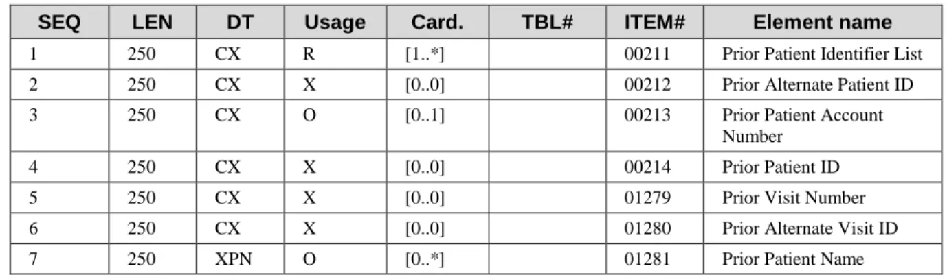
3.30.5.5 MRG – Merge segment
Standard Reference: HL7 Version 2.5, Chapter 3 (Section 3.4.9) This segment contains the supplier patient identifiers list to be merged. 760
Table 3.30-5: MRG - Merge segment
SEQ LEN DT Usage Card. TBL# ITEM# Element name
1 250 CX R [1..*] 00211 Prior Patient Identifier List
2 250 CX X [0..0] 00212 Prior Alternate Patient ID
3 250 CX O [0..1] 00213 Prior Patient Account
Number
4 250 CX X [0..0] 00214 Prior Patient ID
5 250 CX X [0..0] 01279 Prior Visit Number
6 250 CX X [0..0] 01280 Prior Alternate Visit ID
7 250 XPN O [0..*] 01281 Prior Patient Name
Each of the patient identifiers appearing in the MRG-1 is to be merged with a target patient identifier of the same type in the PID-3.
The type of identifier is a code given by the 5th component of the CX data type. See the 765
commonly used identifier types in the description of the PID segment above. See also the definition of data type CX in the “Common Data Types” section.
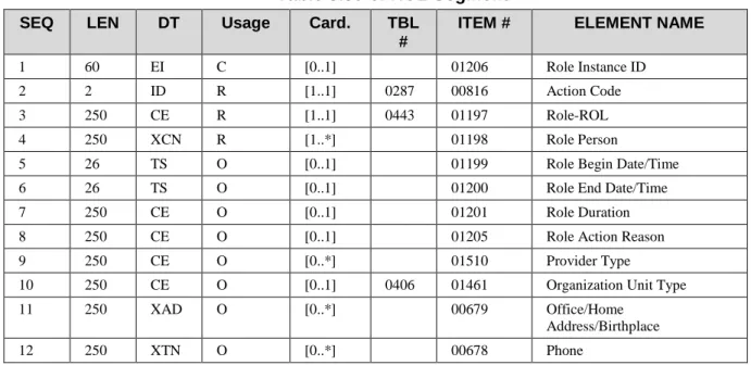
3.30.5.6 ROL – Role segment
Standard Reference: HL7 Version 2.5, Chapter 15 (Section 15.4.7)
The ROL segment communicates information on persons related to the patient. 770
Table 3.30-6: ROL Segment
SEQ LEN DT Usage Card. TBL #
ITEM # ELEMENT NAME
1 60 EI C [0..1] 01206 Role Instance ID
2 2 ID R [1..1] 0287 00816 Action Code
3 250 CE R [1..1] 0443 01197 Role-ROL
4 250 XCN R [1..*] 01198 Role Person
5 26 TS O [0..1] 01199 Role Begin Date/Time
6 26 TS O [0..1] 01200 Role End Date/Time
7 250 CE O [0..1] 01201 Role Duration
8 250 CE O [0..1] 01205 Role Action Reason
9 250 CE O [0..*] 01510 Provider Type
10 250 CE O [0..1] 0406 01461 Organization Unit Type
11 250 XAD O [0..*] 00679 Office/Home
Address/Birthplace
12 250 XTN O [0..*] 00678 Phone
ROL-1 – Role Instance ID (EI), optional. This field is in fact optional in the context of ADT messages.
775
ROL-2 – Action Code (ID), required
ROL-3 – Role-ROL (CE) , required. This field defines the functional involvement of the person. Values are given in User-defined Table 0443:
User-defined Table 0443: Provider role
780
Value Description Used with
AD Admitting PV1-17 Admitting doctor
AT Attending PV1-7 Attending doctor
CP Consulting Provider
FHCP Family Health Care
Professional
PP Primary Care Provider
Value Description Used with
RT Referred to Provider
ROL-4 – Role Person (XCN), required. Identification of the person playing the role.
3.30.5.7 OBX – Observation/Result segment
Standard Reference: HL7 Version 2.5, Chapter 7 (Section 7.4.2)
In transactions ITI-30 and ITI-31, the OBX segment is primarily used to convey patient height 785
and patient weight. For this reason, this segment is described in this section, although it always appears as optional in transactions ITI-30 and ITI-31.
Table 3.30-7: OBX Segment
SEQ LEN DT Usage Card. TBL# ITEM# Element name
1 4 SI O [0..1] 00569 Set ID – OBX
2 2 ID C [1..1] 0125 00570 Value Type
3 250 CE R [1..1] 00571 Observation Identifier
4 20 ST C [0..1] 00572 Observation Sub-ID
5 99999 Varies C [1..1] 00573 Observation Value
6 250 CE O [0..1] 00574 Units
7 60 ST O [0..1] 00575 References Range
8 5 IS O [0..1] 0078 00576 Abnormal Flags
9 5 NM O [0..1] 00577 Probability
10 2 ID O [0..1] 0080 00578 Nature of Abnormal Test
11 1 ID R [0..1] 0085 00579 Observation Result Status
12 26 TS O [0..1] 00580 Effective Date of Reference Range
13 20 ST O [0..1] 00581 User Defined Access Checks
14 26 TS O [0..1] 00582 Date/Time of the Observation
15 250 CE O [0..1] 00583 Producer's ID
16 250 XCN O [0..1] 00584 Responsible Observer
17 250 CE O [0..1] 00936 Observation Method
18 22 EI O [0..1] 01479 Equipment Instance Identifier
19 26 TS O [0..1] 01480 Date/Time of the Analysis
790
OBX-2 Value Type (ID), conditional. This field contains the type of observation.
Example: “NM” for a numeric observation such as patient weight or patient height.
Condition predicate: This field SHALL be valued if OBX-5 “Observation Value” is present. It MAY be valued otherwise.
OBX-3 Observation Identifier (CE), required
The usage of LOINC® vocabulary is strongly recommended. Details of this free vocabulary can be found at http://www.loinc.org. The first and third sub-fields, “Identifier” and “Name of Coding System” are required in all transactions. The value of the “Name of Coding System” in the case of LOINC is “LN”.
800
Example of the code used with the patient weight: 3142-7^BODY WEIGHT (STATED)^LN
OBX-4 Observation Sub-ID (CE), conditional
This field is used to distinguish between multiple OBX segments with the same observation ID. Condition predicate: When field OBX-3 “Observation Identifier” has an identical value in two or more OBX segments of the message, field OBX-4 “Observation Sub-ID” SHALL be populated 805
with a distinct value in each of these OBX segments.
OBX-5 Observation Value (Varies), conditional. This field contains the value of the observation itself.
Condition predicate: This field SHALL be valued if OBX-11 “Observation Result Status” has another value than “X”, “D”, “N” or “I” and if OBX-8 “Abnormal Flags” is empty. In all other 810
cases this field MAY be valued.
OBX-11 Observation Result Status (ID), required.
This field contains the status of the results. In messages of transactions ITI-30 and ITI-31, this status is most commonly “F” (Final).
Example of use of the OBX segment to carry the patient weight and height: 815
OBX|1|NM|3142-7^BODY WEIGHT (STATED)^LN||62|kg|||||F OBX|2|NM|8303-0^BODY HEIGHT^LN||1.70|m|||||F
3.30.5.8 AL1 – Patient Allergy Information segment
Standard Reference: HL7 Version 2.5, Chapter 3, Section 3.4.6
In transactions ITI-30 and ITI-31, the AL1 segment is used to inform the receiver of patient 820
allergies. For this reason, this segment is described in this section, although it always appears as optional in transactions ITI-30 and ITI-31.
Table 3.30-8: AL1 Segment
SEQ LEN DT Usage Card. TBL# ITEM# Element name
1 4 SI R [1..1] 00203 Set ID – AL1
2 250 CE O [0..1] 0127 00204 Allergen Type Code
3 250 CE R [1..1] 00205 Allergen Code/Mnemonic/Description
4 250 CE O [0..1] 0128 00206 Allergen Severity Code
5 15 ST O [0..*] 00207 Allergen Reaction Code
6 8 DT X [0..0] 00208 Identification Date
One or more AL1 segments may appear in the messages of transactions ITI-30 and ITI-31 if any allergies have been identified for the patient at time of registration.
3.30.6 Interactions
All messages of this transaction shall be acknowledged by the ACK message as stated in ITI TF-2x: Appendix C. For better readability, the acknowledgement messages are not shown on the 830
interaction diagrams of this transaction.
3.30.6.1 Interaction diagram
Patient Demographics
Source
Patient Demographics
Consumer Create a new
patient
Update patient information
Merge two patients
Change patient identifier list
Link patient information
Unlink patient information
ADT^A28^ADT_A05
ADT^A31^ADT_A05
ADT^A40^ADT_A39
ADT^A47^ADT_A30
ADT^A24^ADT_A24
ADT^A37^ADT_A37
Figure 3.30-1: Interactions of Transaction ITI-30
835
3.30.6.2 Create New Patient - ADT^A28^ADT_A05
3.30.6.2.1 Trigger Event
This message is sent by a Patient Demographics Supplier to a Patient Demographics Consumer to communicate the demographics of a new patient, as well as related information.
MSH-9 is valued ADT^A28^ADT_A05. 840
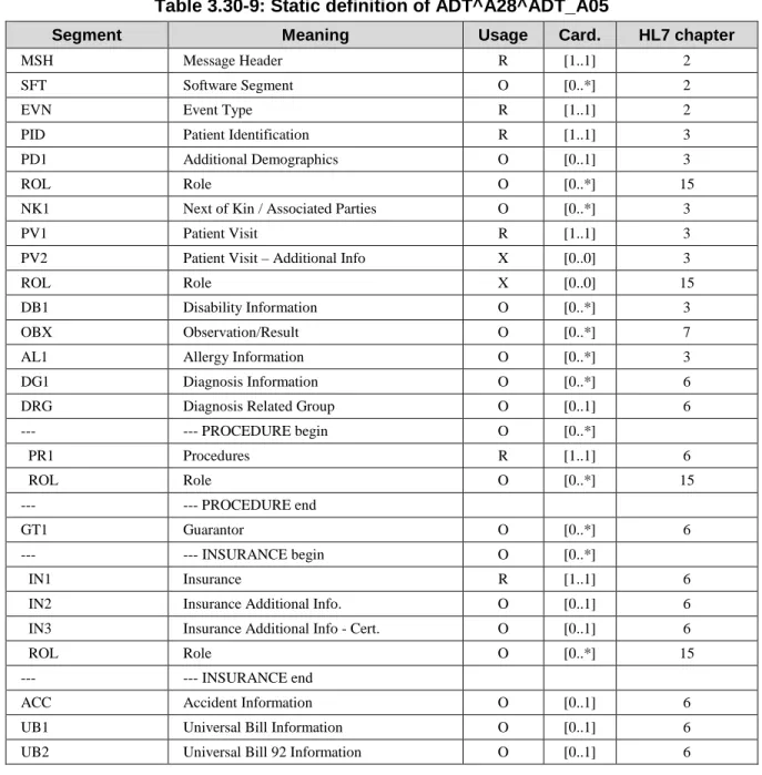
3.30.6.2.2 Message Static Definition
Table 3.30-9: Static definition of ADT^A28^ADT_A05
Segment Meaning Usage Card. HL7 chapter
MSH Message Header R [1..1] 2
SFT Software Segment O [0..*] 2
EVN Event Type R [1..1] 2
PID Patient Identification R [1..1] 3
PD1 Additional Demographics O [0..1] 3
ROL Role O [0..*] 15
NK1 Next of Kin / Associated Parties O [0..*] 3
PV1 Patient Visit R [1..1] 3
PV2 Patient Visit – Additional Info X [0..0] 3
ROL Role X [0..0] 15
DB1 Disability Information O [0..*] 3
OBX Observation/Result O [0..*] 7
AL1 Allergy Information O [0..*] 3
DG1 Diagnosis Information O [0..*] 6
DRG Diagnosis Related Group O [0..1] 6
--- --- PROCEDURE begin O [0..*]
PR1 Procedures R [1..1] 6
ROL Role O [0..*] 15
--- --- PROCEDURE end
GT1 Guarantor O [0..*] 6
--- --- INSURANCE begin O [0..*]
IN1 Insurance R [1..1] 6
IN2 Insurance Additional Info. O [0..1] 6
IN3 Insurance Additional Info - Cert. O [0..1] 6
ROL Role O [0..*] 15
--- --- INSURANCE end
ACC Accident Information O [0..1] 6
UB1 Universal Bill Information O [0..1] 6
UB2 Universal Bill 92 Information O [0..1] 6
3.30.6.2.3 Comments on segment usage
The ROL segment following the PID/PD1 segments is used to communicate “person level” 845
providers having an ongoing relationship with the patient, such as “family health care provider” and “primary care provider”.
The PV1 segment in this message is required in the HL7 message structure, but it is a pseudo PV1 carrying the only required field PV1-2 “Patient Class” with the value “N” meaning “Not applicable”. This message does not convey any visit information.
The PV2 segment is not supported here, for the same reason.
The ROL segment following the PV1/PV2 segments is not supported here, for the same reason. One or more OBX segments may be present to carry “permanent observations” such as the patient weight or height.
The ROL segment following the IN1/IN2/IN3 segments serves to communicate providers related 855
to a specific insurance carrier.
3.30.6.2.4 Expected actions
The receiver shall add this new patient to its database, and shall report the result of this operation (success / error) in an acknowledgment message returned to the sender.
3.30.6.3 Update patient information - ADT^A31^ADT_A05
860
3.30.6.3.1 Trigger Event
This message is sent by a Patient Demographics Supplier to a Patient Demographics Consumer to update the demographics of an existing patient.
MSH-9 is valued ADT^A31^ADT_A05.
3.30.6.3.2 Message Static Definition
865
Table 3.30-10: Static definition of ADT^A31^ADT_A05
Segment Meaning Usage Card. HL7 chapter
MSH Message Header R [1..1] 2
SFT Software Segment O [0..*] 2
EVN Event Type R [1..1] 2
PID Patient Identification R [1..1] 3
PD1 Additional Demographics O [0..1] 3
ROL Role O [0..*] 15
NK1 Next of Kin / Associated Parties O [0..*] 3
PV1 Patient Visit R [1..1] 3
PV2 Patient Visit – Additional Info X [0..0] 3
ROL Role O [0..*] 15
DB1 Disability Information O [0..*] 3
OBX Observation/Result O [0..*] 7
AL1 Allergy Information O [0..*] 3
DG1 Diagnosis Information O [0..*] 6
DRG Diagnosis Related Group O [0..1] 6
--- --- PROCEDURE begin O [0..*]
PR1 Procedures R [1..1] 6
Segment Meaning Usage Card. HL7 chapter
--- --- PROCEDURE end
GT1 Guarantor O [0..*] 6
--- --- INSURANCE begin O [0..*]
IN1 Insurance R [1..1] 6
IN2 Insurance Additional Info. O [0..1] 6
IN3 Insurance Additional Info - Cert. O [0..1] 6
ROL Role O [0..*] 15
--- --- INSURANCE end
ACC Accident Information O [0..1] 6
UB1 Universal Bill Information O [0..1] 6
UB2 Universal Bill 92 Information O [0..1] 6
3.30.6.3.3 Comments on segment usage
To accommodate the situation in which the receiver does not know the patient, this message is populated with complete up-to-date demographics for the patient.
870
The ROL segment following the PID/PD1 segments is used to communicate “person level” providers having an ongoing relationship with the patient, such as “family health care provider” and “primary care provider”.
The PV1 segment in this message is required in the HL7 message structure, but it is a pseudo PV1 carrying the only required field PV1-2 “Patient Class” with the value “N” meaning “Not 875
applicable”. This message does not convey any visit information. The PV2 segment is not supported here, for the same reason.
The ROL segment following the PV1/PV2 segments is not supported here, for the same reason. One or more OBX segments may be present to carry “permanent observations” such as the patient weight or height.
880
The ROL segment following the IN1/IN2/IN3 segments serves to communicate providers related to a specific insurance carrier.
3.30.6.3.4 Expected actions
The receiver shall update the patient record in its database, and shall report the result of this operation (success / error) in an acknowledgment message returned to the sender. If the receiver 885
did not previously have a record for this patient, it shall insert this patient into its database.
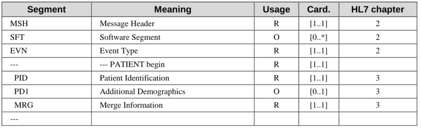
3.30.6.4 Merge two patients - ADT^A40^ADT_A39
This message is to be supported with the “Merge” Option of Transaction ITI-30.
3.30.6.4.1 Trigger Event
The Patient Demographics Supplier notifies to a Patient Demographics Consumer, the merge of 890