Many technologies are used to deliver metro and wide-area services. Layer 1 TDM technologies used to deliver private line services include T1 and T3 copper circuits, and SONET-based optical circuits. Layer 2 technologies used to deliver data services over the Layer 1 TDM technologies include Frame Relay, ATM and PPP.
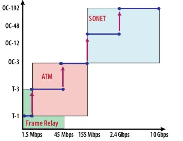
These legacy technologies provide inflexible bandwidth scalability because the bandwidth is dictated by the technology. When a service provider or enterprise needs to add bandwidth, they either bond multiple circuits together or upgrade their network and equipment to support a new technology. This results in non-linear bandwidth that may not be at the bandwidth increment that the subscriber needs or, more importantly, can afford.
OC-192 OC-48 OC-12 OC-3 T-3
SONET
ATM
Frame Relay
T-1 1.5 Mbps 45 Mbps 155 Mbps 2.4 Gbps 10 GbpsFigure 1: Non-Linear Bandwidth Increments of Legacy Technologies
Bonding circuits together results in additional ports on the network equipment (CapEx). Bonding circuits also increases operational complexity (OpEx), since each circuit is managed individually and the data service is managed over the bonded circuits. Finally, new OAM tools are required as technologies are changed to support higher bandwidths.
Carrier Ethernet addresses the limitations of legacy technology by providing flexible bandwidth scalability. Once an Ethernet service is deployed, bandwidth can be added simply through remote provisioning up to the Ethernet port speed. This enables the service provider to sell, or enterprise to deploy, the amount of bandwidth subscribers actually need, rather than forcing them to buy a particular amount of bandwidth dictated by the legacy technology. In addition, it is not necessary to send a service technician to the customer premises, which generates additional OpEx savings when compared to legacy services. With Carrier Ethernet, subscribers can now use the same, well-understood Ethernet technology for their LAN, MAN and WAN connections. This reduces CapEx for the equipment to connect to the service. It also simplifies operations and training.
Carrier Ethernet versus Ethernet
When most think of Ethernet, they think of Ethernet as a LAN technology. Three fundamental aspects differentiate Ethernet LANs from Carrier Ethernet:
• Each user connects to a dedicated Ethernet port on the LAN • The LAN serves one organization
• The LAN is inside the building
LAN
Figure 2: Ethernet LAN
Ethernet is prefixed with the word “Carrier” to indicate its usage and additional capabilities. These additional capabilities enable end-users to build MANs and WANs, and service providers to build network infrastructure or deliver Ethernet-based MAN or WAN
With legacy technologies, adding
bandwidth often requires a technology
change, causing service disruption and
longer time to revenue.
Carrier Ethernet provides flexible
bandwidth increments and the ability to
add new services using one technology.
Carrier Ethernet augments the original set of Ethernet LAN
technologies with support for the new capabilities required to deliver services. Three fundamental aspects differentiate Carrier Ethernet networks from Ethernet LANs:
• An entire organization connects to a Carrier Ethernet “port” at a given subscriber location
• The Carrier Ethernet network serves many organizations • The Carrier Ethernet network is outside the building across a
wide area
IP Network
& Services
Carrier
Ethernet
Network
Figure 3: Carrier Ethernet Network
Carrier Ethernet Ecosystem
The MEF defines Carrier Ethernet based on five attributes as
illustrated in Figure 4. Carrier Ethernet uses many of the Ethernet LAN technologies but required further augmentation in order to function as a service delivery technology for MANs and WANs. The five MEF Carrier Ethernet attributes focus on these service delivery aspects for Ethernet usage outside of the LAN.
Scalability Standardized Services Quality of Service Service Management Reliability
Carrier
Ethernet
Figure 4: MEF's Five Attributes of Carrier Ethernet
Carrier Ethernet Taxonomy
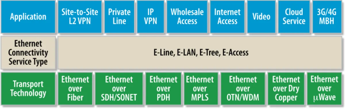
Carrier Ethernet is used for different purposes in the network. The Carrier Ethernet taxonomy, shown in Figure 5, illustrates the interrelationships among its different roles in the network.
Application
Ethernet
Connectivity
Service Type
Transport
Technology
Ethernet
over
Fiber
Ethernet
over
SDH/SONET
Ethernet
over
PDH
Ethernet
over
MPLS
Ethernet
over
OTN/WDM
Ethernet
over Dry
Copper
Ethernet
over
μ
Wave
E-Line, E-LAN, E-Tree, E-Access
Site-to-Site
L2 VPN
Private
Line
VPN
IP
Wholesale
Access
Internet
Access
Video
Service
Cloud
3G/4G
MBH
Carrier Ethernet Infrastructure
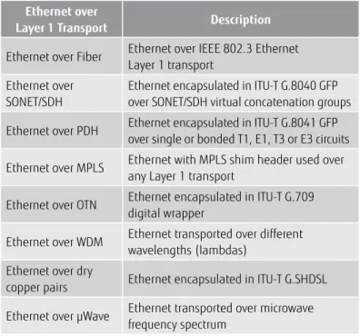
Carrier Ethernet is an infrastructure technology that can be
implemented over many different types of Layer 1 transport network technologies. Figure 6 provides more detail about the transport technologies used to deliver the Ethernet services listed in Figure 5.
Ethernet over
Layer 1 Transport Description
Ethernet over Fiber Ethernet over IEEE 802.3 Ethernet Layer 1 transport
Ethernet over SONET/SDH
Ethernet encapsulated in ITU-T G.8040 GFP over SONET/SDH virtual concatenation groups Ethernet over PDH Ethernet encapsulated in ITU-T G.8041 GFP
over single or bonded T1, E1, T3 or E3 circuits Ethernet over MPLS Ethernet with MPLS shim header used over
any Layer 1 transport
Ethernet over OTN Ethernet encapsulated in ITU-T G.709 digital wrapper
Ethernet over WDM Ethernet transported over different wavelengths (lambdas)
Ethernet over dry
copper pairs Ethernet encapsulated in ITU-T G.SHDSL Ethernet over µWave Ethernet transported over microwave
frequency spectrum
Figure 6: Ethernet over Different Layer 1 Transport Types
Ethernet Connectivity Service Type
Carrier Ethernet is also a service delivery technology used to deliver a variety of MEF-defined types of connectivity services, including E-Line, E-LAN and E-Tree for retail services, and E-Access for wholesale access services (discussed in the section covering Ethernet service definitions). Ethernet connectivity services are delivered over various Carrier Ethernet transport technologies, leveraging a heterogeneous set of transport network technologies.
Carrier Ethernet-Enabled Applications
The applications enabled by a Carrier Ethernet network infrastructure include Ethernet Layer 2 networking and Ethernet access to IP (Layer 3) services. Figure 7 provides more details for the Ethernet-enabled applications listed in Figure 5.
Application Description
Site-to-site Layer 2 VPNs
High bandwidth and more flexible replacement for the popular Frame Relay Layer 2 VPNs
EPL
Similar characteristics to a Layer 1 private line but delivered using Ethernet interfaces
Wholesale Ethernet access
First/last mile Ethernet services enabling service providers to reach out-of-franchise customer premises
3G/4G cell site mobile backhaul
Interconnecting 3G/4G base stations at cell sites to their base station controllers at a mobile switching center
Ethernet access to IP services
•Ethernet access to managed IP VPNs •Ethernet dedicated Internet access •Ethernet access to cloud services • Ethernet backhaul of IP video from
DSLAM, GePON or CMTS aggregator
Figure 7: Ethernet-Enabled Applications
Ethernet or MPLS for Carrier Ethernet?
There has been a misconception that MPLS is required to implement a Carrier Ethernet network. This is partly because when the market was in its infancy, service providers used enterprise-class Ethernet switches in their first Carrier Ethernet deployments. Hence, the “switched Ethernet services” delivered over these networks gave Carrier Ethernet a bad reputation. While these services could provide higher bandwidth and more flexible connectivity options than their legacy counterparts, they lacked any meaningful performance that could be specified in a high-quality SLA like those that customers received for their legacy services. Just as MPLS was used to improve the performance of “best-effort” IP networks, it was again utilized to improve the performance of these early Carrier Ethernet network deployments. MPLS brought a number of useful capabilities such as fast-reroute to significantly reduce network segment protection and restoration times, and VPLS to increase the scalability required in metro networks with large numbers of subscribers.
Carrier Ethernet technologies and standards have come a long way since those early days and can now provide the performance and scalability that were once only available through the use of MPLS technologies.
What Problem are You Trying to Solve?
Whether to use an Ethernet-centric or MPLS-centric technology implementation of Carrier Ethernet, you need to understand the problem you are trying to solve.
• Are you aggregating triple-play IP services in a metro network? • Are you delivering metro or long-haul Ethernet services? • Do you need to transport legacy services, such as ATM or Frame
Relay, alongside your Ethernet and IP services over a converged network?
• Are you backhauling 2G (TDM), 3G (ATM) and 4G Ethernet services from cell sites, or only 3G (Ethernet) and 4G?
For delivering Ethernet services, aggregating IP services from your access/aggregation networks or backhauling 3G or 4G IP wireless data services from Ethernet-attached devices, an Ethernet-centric approach should result in lower OpEx than an MPLS-centric approach.
For transporting or backhauling multiservice traffic over a converged network, such as a combination of Ethernet, TDM and ATM, an MPLS-centric approach makes more sense given the inherent strengths of MPLS in supporting multiservice traffic types. While Ethernet-centric technologies such as circuit emulation exist for transporting multiservice traffic, they have achieved limited deployments given the longer heritage of multiservice support in MPLS.
Finally, you need to determine if there is a business case to converge Ethernet and legacy traffic over a common network infrastructure. If your legacy TDM and ATM services have limited to no growth, is it worth the time and expense to converge them over the same network with your high-growth Ethernet and IP services? The legacy network may already be amortized and operating at optimal efficiency, so the best approach may be to leave it in place until the legacy services significantly decline or are replaced by Ethernet.
Which Organization is Deploying Carrier Ethernet?
When assessing the implementation choices for Carrier Ethernet, it is essential to consider the organization’s skill set and OAM tools available to deploy and support a given technology.
A transport/transmissions organization deploys SONET/SDH, WDM or OTN Layer 1-centric technologies, which are light in protocols, and the OAM tools support circuit-based (P2P connection-oriented) applications. Conversely, a data organization deploys IP and MPLS-centric technologies, which use many protocols, and the OAM tools support any-to-any connectionless applications. They may implement some traffic engineering to steer traffic down certain paths for certain applications but the latter technologies are fundamentally connectionless.
What are the Business Case and ROI Objectives?
It is easy to have an academic discussion to converge all traffic over a common network infrastructure. However, there must be business and financial justification to, for example, converge TDM and legacy services, such as ATM and Frame Relay, over a common Carrier Ethernet network. If the TDM or legacy service growth rate is limited or flat, is there a business case to migrate these services to the Carrier Ethernet network or simply keep them on their current network?
Most services are moving to IP so it is often possible to restrict legacy services to the access network and provide a gateway to terminate legacy protocols, extract the IP payloads and transport them over a Carrier Ethernet network, for example, by using a VoIP gateway to convert legacy PBX voice traffic to VoIP.
As you evaluate these business considerations, it becomes a much simpler choice to determine whether to take an Ethernet-centric or MPLS-centric approach with your Carrier Ethernet implementation.
Carrier Ethernet Building Blocks
This section describes the building blocks which are used to create an Ethernet Service.
Ethernet Service Demarcation
Ethernet service demarcation consists of two fundamental interface types, namely the Ethernet UNI and Ethernet ENNI. UNIs and ENNIs provide delineation between the responsibilities of buyers and sellers of services. Service demarcation is important for service assurance and troubleshooting. In the event of a service outage, service demarcation determines who is responsible for troubleshooting the service up to the UNI or ENNI to which they attach.
Ethernet technologies have come a
long way and can now provide the
same capabilities that were once only
available through MPLS.
If the traffic is all Ethernet-based, an
Ethernet-centric approach to Carrier
Ethernet makes more sense.
If you need to transport Ethernet and
legacy services over a converged network,
an MPLS-centric approach to Carrier
Ethernet makes more sense.
Ethernet UNI
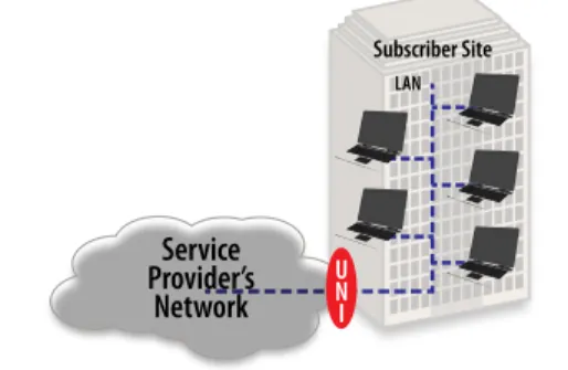
The Ethernet UNI is the physical Ethernet interface to which the end-user subscriber attaches their network to the service. Subscriber sites always attach to the service provider’s network using a UNI. Refer to Figure 8.
Service
Provider’s
Network
UNI LAN Subscriber SiteFigure 8: UNI Demarcation Between Service Provider and Subscriber
The UNI also provides the demarcation between the responsibilities of the subscriber and service provider. In the event of a service outage, the service provider is responsible for troubleshooting the service from their network up to the UNI and the subscriber is responsible for their LAN up to the UNI.
Ethernet ENNI
The Ethernet ENNI is the physical Ethernet interface that provides service demarcation between two service providers’ networks. Each service provider is responsible for their respective side of the service demarcation, up to the ENNI interconnection point. Refer to Figure 9.
Wholesale Access Provider Retail Service Provider E N N I
Figure 9: ENNI Service Demarcation between Providers
The MEF defines two types of service providers who interconnect at an ENNI. One is called an Operator and the other is called a Service Provider. Per the MEF definitions, the Service Provider sells Ethernet services to end user buyers whose sites are connected to the network via an Ethernet UNI. The Operator sells Ethernet services to the Service Provider whose networks are interconnected via an Ethernet ENNI. The Retail Service Provider in Figure 9 is the MEF’s “Service Provider” who would have the business relationship with the end user Subscriber. The Wholesale Access Provider is the MEF’s Operator who would have a business relationship the Retail Service Provider and not the end user Subscriber.
An Operator is used when the Service Provider cannot reach all end user Subscriber locations on their network facilities. These Subscriber locations are “off-net” or “out-of-franchise”. In this case, the Service Provider must rely on another Operator’s network to reach these off-net Subscriber locations.
Ethernet Virtual Connectivity
The MEF has defined two types of Ethernet virtual connectivity constructs, namely, the EVC and the OVC. EVCs and OVCs enable one to better visualize a service rather than show the complete physical connectivity between the UNI or ENNI endpoints.
Ethernet Virtual Connections
An EVC is the logical association between two or more UNIs. EVCs are useful for describing the virtual connectivity of a service between UNI endpoints. The MEF has defined three types of EVCs, namely MP2MP, P2P and RMP). An EVC is a retail Ethernet service construct, meaning that it is used to describe the logical connectivity of a service delivered between a service provider and an end user subscriber.
The MP2MP EVC is most similar to Ethernet’s usage in a LAN, which is technically referred to as CLE. An MP2MP EVC provides a broadcast domain such that all Ethernet service frames associated with the EVC are visible to and accessible by all UNI members of the EVC. An MP2MP EVC provides LAN-like connectivity but over greater distances, interconnecting typically three or more remote locations. Refer to Figure 10. MP2MP EVC UNI UNI UNI UNI UNI
P2P EVCs provide connectivity similar to other P2P MAN/WAN
connectivity technologies such as T1s/E1s or Frame Relay. The P2P EVC provides connectivity between two UNIs where all frames sent to the EVC from one UNI are received by the other UNI. Refer to Figure 11.
P2P EVC UNI
UNI
Figure 11: Point-to-Point EVC
RMP EVCs are a special case of a MP2MP EVC where one of the UNIs is designated as the Root UNI and the remaining UNIs are designated as Leaf UNIs. A Root UNI has full connectivity to all other UNIs, while Leaf UNIs only have connectivity to the Root UNI. The RMP EVC is used for aggregation applications, where the Leaf UNIs only need to communicate to the Root UNI and not other Leaf UNIs. Refer to Figure 12. The RMP EVC is also used for broadcast applications. For example, in a broadcast video application, the Root UNI could broadcast TV channels to all Leaf UNIs and the Leaf UNIs send channel-changing information from each subscriber’s set-top box back to the Root UNI. Another application is Internet access aggregation, where the Root UNI has a connection to the Internet and the Leaf UNIs connect to the Internet via the Root UNI’s Internet connection.
RMP EVC Leaf
UNI LeafUNI LeafUNI
Root UNI
Figure 12: Rooted Multipoint EVC
The RMP EVC is very similar to a hub-and-spoke topology where a hub UNI has a set of service multiplexed P2P EVCs. However, the latter case consists of N-1 EVCs (where N is the number of UNIs) where the RMP implementation requires only one EVC. Refer to Figure 13.
3 P2P EVC Spoke
UNI SpokeUNI SpokeUNI Hub UNI
1 RMP EVC Leaf
UNI LeafUNI LeafUNI Root
UNI
Figure 13: RMP and P2P EVC Hub and Spoke Comparison
Since service providers typically charge for each EVC, the subscriber should be able to purchase a lower-cost service using an RMP EVC when compared to a P2P EVC implementation for a hub-and-spoke application. An additional benefit of an RMP EVC is that it can broadcast traffic from the Root UNI to all Leaf UNIs. A hub-and-spoke implementation using P2P EVCs requires an external device, such as a router or Ethernet switch, to replicate the traffic sent over each EVC. Operator Virtual Connections
An OVC is the logical association between a UNI and ENNI or between two ENNIs. OVCs are useful for describing the virtual connectivity of a service between UNI-ENNI or ENNI-ENNI endpoints. An OVC is also a segment of an EVC whereby two or more OVCs can be concatenated to create an EVC. An EVC that traverses multiple provider networks consists of a sequence of OVCs.
An OVC is a wholesale Ethernet service construct, meaning that it is used to describe the logical connectivity of a service delivered between providers. The MEF has currently defined two types of OVCs, namely MP2MP and P2P. Today, P2P OVCs are more popular, owing to their simplicity over MP2MP OVC implementations.
MP2MP OVC UNI UNI UNI ENNI
Figure 14: Multipoint-to-Multipoint OVC
MP2MP OVCs are conceptually similar to MP2MP EVCs, except that with OVCs, one of the endpoints is an ENNI. Refer to Figure 14. The MEF has currently defined EVCs to have only UNI endpoints.
P2P OVCs are conceptually similar to P2P EVCs, except that at least one of the endpoints must be an ENNI. Refer to Figure 15.
P2P OVCs
UNI ENNI
ENNI ENNI
Figure 15: Point-to-Point OVC Types
An OVC with a UNI and an ENNI endpoint is used for Ethernet access services where an Ethernet access provider provides a UNI at the subscriber’s premises on behalf of an Ethernet service provider for a subscriber’s site that is “off-net” or “out-of-franchise.” This means the Ethernet service provider does not have network facilities to reach the subscriber’s site, and the site can only be reached through an Ethernet access provider with network facilities that reach the site.
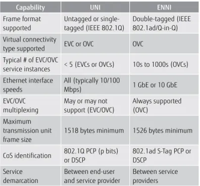
How is a UNI Different from an ENNI?
A UNI and an ENNI are both Ethernet ports that provide demarcation points between buyers and sellers of services. However, there are some fundamental differences between the two regarding their capabilities and how they are typically deployed. Refer to Figure 16 for a comparison of their differences and capabilities.
Capability UNI ENNI
Frame format supported Untagged or single- tagged (IEEE 802.1Q) Double-tagged (IEEE 802.1ad/Q-in-Q) Virtual connectivity
type supported EVC or OVC OVC Typical # of EVC/OVC
service instances < 5 (EVCs or OVCs) 10s to 1000s (OVCs) Ethernet interface speeds All (typically 10/100 Mbps) 1 GbE or 10 GbE EVC/OVC multiplexing
May or may not support (EVC/OVC) Always supported (OVC) Maximum transmission unit frame size
1518 bytes minimum 1526 bytes minimum CoS identification 802.1Q PCP (p bits)
or DSCP 802.1ad S-Tag PCP or DSCP Service demarcation Between end-user and service provider
Between service providers
Figure 16: UNI and ENNI Capability Comparison
Putting It All Together
Figure 17 shows how all of the Carrier Ethernet building blocks can be put together to deliver a point-to-point Ethernet service.
Wholesale
Access Provider Service ProviderRetail UNI
Subscriber Subscriber
UNI ENNI Wholesale ENNI
Transport Provider EVC OVC2
OVC1 OVC3
Figure 17: “Big Picture” View of Carrier Ethernet Building Blocks
UNIs provide service demarcation between provider and subscriber networks. ENNIs provide service demarcation between different providers’ networks. Each provider constructs an OVC between their service demarcation points. Finally, in this example, a P2P EVC is constructed between the two UNIs to deliver the end-to-end service between the subscriber locations.
Ethernet Service Definitions
Ethernet services are defined in the MEF's Ethernet services definition framework. This framework defines and categorizes services based on an Ethernet service type, its associated service attributes and parameters, and whether the service is port-based (VLAN-unaware) or VLAN-based (VLAN-aware). A port-based service does not distinguish between Ethernet frames that are untagged, priority-tagged or VLAN-tagged. It forwards all of them as they arrive at the UNI. A VLAN-based service does distinguish between the different Ethernet frame types, enabling multiple services to be multiplexed onto a single UNI. A port-based service is simpler to deploy, but lacks the flexibility of a VLAN-based service.
The Ethernet service type categorizes a particular service by the type of connectivity it provides and whether it is an EVC-based or OVC-based service.
Ethernet
Service
Type
Ethernet
Service
Attribute
Ethernet
Service
Attribute
Parameter
EVC-Based Services
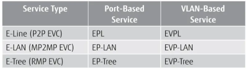
The MEF has defined three service types used to categorize service definitions based on their type of EVC (connectivity). Each service definition consists of an EVC and two or more UNIs based on the capability of the EVC type.
Ethernet service providers deliver the EVC-based services depicted in Figure 19 to buyers that require services to begin and end on an Ethernet UNI.
Service Type Port-Based
Service
VLAN-Based Service
E-Line (P2P EVC) EPL EVPL E-LAN (MP2MP EVC) EP-LAN EVP-LAN E-Tree (RMP EVC) EP-Tree EVP-Tree
Figure 19: EVC-based Ethernet Services
OVC-Based Services
In the beginning of 2010, the MEF started defining a new service type called E-Access, used to categorize new OVC-based service definitions. These service definitions utilize a P2P OVC with one UNI endpoint and one ENNI endpoint. There are port-based and VLAN-based E-Access service definitions under development in the MEF. Their names are listed in Figure 20.
Service Type Port-Based Service VLAN-Based Service
E-Access (P2P OVC) Access EPL Access EVPL
Figure 20: OVC-based Ethernet Services
E-Access service types are typically used by wholesale Ethernet access providers who sell their services to retail Ethernet service providers who are delivering an EVC-based service to their end-user subscribers. Access EPL, formerly known as E-APL, is similar to EPL where it supports a single OVC-based service instance at the UNI. Access EPL and EPL are port-based services. However, an Access EPL supports a service multiplexed ENNI at the other endpoint of the OVC, versus a UNI for an EPL. Access EPL is the simplest form of OVC-based service because it requires no VLAN-awareness at the UNI. This eliminates any customer VLAN ID mapping coordination between the wholesale Ethernet access provider who delivers the Access EPL and the retail Ethernet service provider peering with the Ethernet access provider at the ENNI.
Access EVPL, formerly known as E-AVPL, supports multiple OVC-based service instances at the UNI. Like Access EPL, it supports a service multiplexed ENNI at the other endpoint of the OVC. Like EVPL, Access EVPL supports multiple service instances at the UNI because both are VLAN-based services. Access EVPL is more complex than Access EPL and does require C-VLAN ID and PCP mapping coordination between the wholesale Ethernet access provider and retail Ethernet service provider peering at the ENNI. However, Access EVPL provides additional flexibility in delivering multiple revenue-generating services at the same UNI. Access EVPL is more cost-effective than Access EPL for wholesale and retail service providers and end-user customers who require multiple services. This is because Access EPL would require a separate Ethernet UNI for each service, resulting in additional equipment CapEx to connect to and deliver the service.
Ethernet Service Attributes
Several attributes define an Ethernet service. This section describes some of the more significant ones.
Bandwidth Profiles
A bandwidth profile defines how rate enforcement of Ethernet frames is applied at an external interface, either a UNI or ENNI. Ingress bandwidth profiles are applied to Ethernet frames entering the external interface and associated with an EVC or OVC. Egress bandwidth profiles are applied to Ethernet frames exiting the EVC or OVC at an external interface. Bandwidth profiles enable a service provider to also offer “sub-rate” service bandwidth, which is bandwidth below the UNI or ENNI speed. The subscriber benefits by purchasing only the amount of bandwidth needed, and service providers benefit by limiting the amount of bandwidth entering their network per the terms of the SLA. Bandwidth profiles also enable multiple EVCs (or OVCs) to be supported on a single UNI by dividing up the interfaces’ bandwidth among the multiple EVCs or OVCs.
There are three types of ingress and egress bandwidth profiles that can be applied at a UNI endpoint. Each provides increasingly more granularity in dividing the bandwidth at the UNI.
• Per UNI
• Per EVC (or OVC) at a UNI
• Per EVC (or OVC) per COS ID at a UNI
There are two types of ingress and egress bandwidth profiles that can be applied at an ENNI:
• Per OVC at an ENNI
• Per OVC per CoS ID at an ENNI Bandwidth Profile per UNI
This type of bandwidth profile applies to the entire UNI regardless of the number of EVCs (or OVCs) which are present. It is only useful for port-based services such as EPL or Access EPL, which provide a single EVC or OVC, respectively, at the UNI.
Bandwidth Profile per EVC (or OVC) at a UNI
This type of bandwidth profile applies to each EVC (or OVC) at the UNI. This is useful for services with multiple EVCs (or OVCs) at a UNI, such as EVPL or Access EVPL. It enables the UNI bandwidth to be divided up among each EVC (or OVC). When there is a single EVC or OVC at the UNI, the bandwidth profile per EVC (or OVC) provides comparable functionality as the bandwidth profile per UNI. Figure 21 illustrates how a UNI’s bandwidth is divided up among three EVCs using the bandwidth profile per EVC. A similar example could also be illustrated for three OVCs at a UNI.
UNI
EVC
3EVC
2EVC
1BWP per EVC
1BWP per EVC
2BWP per EVC
3Figure 21: Bandwidth Profile per EVC
Bandwidth Profile per EVC (or OVC) per CoS ID at a UNI
This type of bandwidth profile applies to Ethernet frames belonging to each CoS of an EVC (or OVC). This is useful for services with an EVC (or OVC) at a UNI, which support multiple classes of service. Each CoS is identified by its Ethernet PCP (also known as 802.1p) or IP DSCP. This bandwidth profile enables the EVC bandwidth to be partitioned by CoS. Figure 22 illustrates three bandwidth profiles per CoS ID for EVC1 and a bandwidth profile for EVC2 at the UNI. A similar example could also be illustrated for two OVCs at the UNI.
UNI
EVC2
EVC
1BWP per EVC1, per CoS ID 6
BWP per EVC1,per CoS ID 4
BWP per EVC1, per CoS ID 2
BWP per EVC
2 CoS ID 2CoS ID 4 CoS ID 6
Figure 22: Bandwidth Profiles (BWP) per EVC per CoS ID and per EVC
Bandwidth Profile Parameters
A bandwidth profile consists of five major parameters: • CIR
• CBS • EIR • EBS • CM
The CIR defines the bandwidth delivered per the SLO defined in the SLA. CIR bandwidth is assured for an EVC or OVC through traffic engineering across the network. To guarantee a CIR, bandwidth must be reserved across all network paths traversed by Ethernet frames associated with an EVC (or OVC). Note that service performance metrics, such as latency or loss, are measured for traffic bandwidth conformant to the CIR. Traffic bandwidth that is not conformant to the CIR is excluded from performance measurements. This non-conformant traffic is considered excess and is eligible to be discarded in the network, based on the traffic management policies for the service provider’s network. The EIR defines the amount of excess traffic bandwidth allowed into the network. EIR increases overall traffic throughput but with no SLOs as with CIR traffic. Traffic at bandwidths exceeding the CIR is considered excess and hence is not delivered per the SLO.
CBS and EBS specify the maximum number of bytes that can be injected into the network and remain conformant with the CIR and EIR, respectively. For example, if a CBS is 50 KB, then 50 KB of Ethernet frames can be injected into and accepted by the network, and thus be considered conformant to the CIR and subject to the SLO. If more than 50 KB are transmitted, the amount in excess of 50 KB will either be discarded if EIR=0 or accepted as excess traffic if EIR≠0. If the excess traffic exceeds the EBS, then it is discarded.
Ethernet frame color is determined using a bandwidth profile through a traffic management function called policing.
Color Conformance Ethernet Frame Delivery Expectation
Conformant to CIR Frames colored green and delivered per the SLO
Non-conformant to CIR Conformant to EIR
Frames colored yellow and may be delivered but with no SLO assurances
Non-conformant to CIR
or EIR Frames colored red and dropped
Ethernet frames are policed as they ingress at a UNI and are declared green if conformant to the CIR/CBS, declared yellow if non-conformant to the CIR/CBS and conformant to the EIR/EBS, or declared red if non-conformant to either CIR/CBS or EIR/EBS. Red-colored frames are always discarded, yellow-colored frames are discarded during times of network congestion and green-colored frames are never supposed to be discarded. If green frames are discarded, then this counts against meeting the SLO. Refer to Figure 23.
CM specifies whether the service provider should utilize any prior color markings of the Ethernet frames that may have been made by the subscriber’s equipment or used on their LAN prior to those frames ingressing the UNI. If the CM is set to operate in color-blind mode, then any prior Ethernet frame coloring is ignored. If CM is set to operate in color-aware mode, then any prior Ethernet frame coloring is factored into subsequent policing decisions.
Most Ethernet service offerings operate in color-blind mode, since subscribers rarely, if ever, apply traffic management in their LANs that would result in any color marking of their Ethernet frames.
EVC/OVC Multiplexing
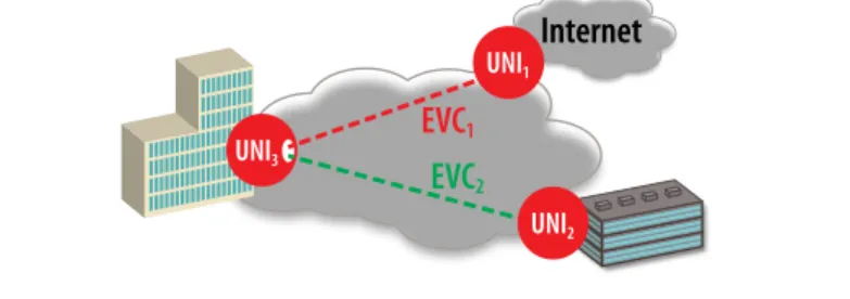
EVC multiplexing at an Ethernet UNI enables multiple services to be delivered over the same Ethernet port. This reduces service cost and CapEx for both the subscriber and service provider. OVC multiplexing can occur at the UNI, providing the same benefit as EVC multiplexing at a UNI. OVCs can also be multiplexed at an ENNI. The best way to understand EVC and OVC multiplexing is via some use cases.
Figure 24 illustrates an example of a hub-and-spoke application, where the site with UNI3 is the hub site and the sites with UNI1 and UNI2 are the spoke sites. EVC1 and EVC2 are multiplexed at UNI3, enabling the hub site location to use a single UNI to support two EVCs.
EVC
1EVC
2UNI3
UNI1
UNI2
Figure 24: Use Case 1: EVC Multiplexing at UNI3
Figure 25 is similar to Figure 24 where EVC1 and EVC2 are multiplexed at UNI3. However, in this example, UNI1 connects to an Internet service provider instead of another business location.
EVC
1Internet
EVC
2 UNI3 UNI1 UNI2Figure 25: Use Case 2: EVC Multiplexing at UNI3
Figure 26 illustrates an example of OVC multiplexing at an ENNI and at Site C’s UNI. In this example, EVCA is between the UNIs for Sites A and C. EVCA can be decomposed into OVC1 and OVC3. The retail service provider purchases OVC1 from the wholesale access provider to reach Site C’s UNI that is off-net and accessible by the wholesale access provider’s network. OVC3 is constructed by the retail service provider between Site A’s UNI that is on-net and the ENNI between the providers. EVCA = OVC1 + OVC3.
OVC3 OVC4 Retail Service Provider
Site A
Site B
Site C
Wholesale Access Provider ENNI EVCB OVC2 OVC1 EVCAFigure 26: OVC Multiplexing at ENNI
EVCB is between the UNIs at Sites B and C. EVCB can be decomposed into OVC2 and OVC4. The retail service provider purchases OVC2 from the wholesale access provider to reach Site C’s UNI that is off-net and accessible by the wholesale access provider’s network. OVC4 is constructed by the retail service provider between Site B’s UNI that is on-net and the ENNI between the providers. EVCB = OVC2 + OVC4.
Ethernet OAM
Deploying Ethernet in a service provider’s network requires the ability to remotely isolate and diagnose network problems. When Ethernet is used as a LAN in a building, one can simply call the technical support person, who takes a brief walk to the wiring closet or networking equipment room to diagnose a problem. A service provider’s network may span dozens to hundreds of miles in a metropolitan area or thousands of miles across a national network so remote diagnosis is a necessity.
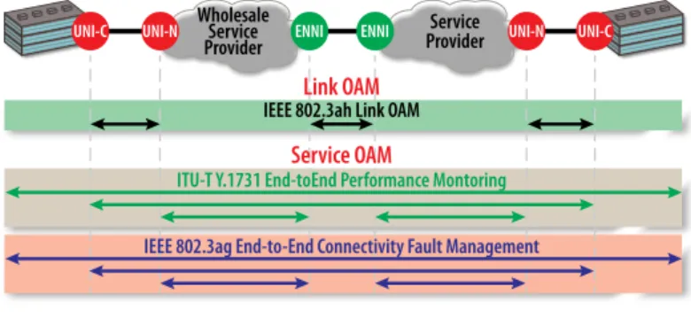
Additionally, Ethernet service providers want to differentiate their service offerings by providing performance objectives which specify the service’s average or maximum packet loss or latency. Ethernet OAM tools enable service provides to meet these requirements. Figure 27 illustrates the Ethernet OAM jurisdictions for Ethernet LOAM and Ethernet SOAM. Service Provider Wholesale Service Provider UNI-C
UNI-C UNI-N ENNI ENNI UNI-N
Link OAM Service OAM
ITU-T Y.1731 End-toEnd Performance Montoring IEEE 802.3ag End-to-End Connectivity Fault Management
IEEE 802.3ah Link OAM
Figure 27: Ethernet OAM Jurisdictions
UNI functionality can be partitioned based on where the functionality is performed. UNI-N functionality is performed in the service provider’s network. UNI-C functionality is performed in the customer premises equipment.
The Ethernet SOAM framework utilizes capabilities defined in IEEE 802.1ag and ITU-T Y.1731. This framework illustrates the service management levels and demarcation points across the network used to check continuity of an EVC or OVC. The framework defines administrative levels whereby different user types can access certain Ethernet SOAM capabilities. These levels are called MAs in IEEE 802.1ag and MEGs in ITU-T Y.1731 standards. The MEG terminology is used more predominantly, so this paper uses it in the remaining discussions. There are eight levels of MEGs; different levels are used between subscriber sites and among the different service providers that may be interconnected when delivering an end-to-end EVC to a subscriber. Refer to Figure 28.
Service Provider Wholesale
Service
Provider UNI-C
UNI-C UNI-N ENNI ENNI UNI-N
Subscriber MEG Service Provider MEG
Subscriber Subscriber
Wholesale Provider MEG
MEP MIP
Service Provider MEG
Figure 28: Ethernet SOAM Framework
MEPs define the endpoints (UNI or ENNI) of an EVC or OVC. MEPs also define the network domain boundaries for which SOAM is performed by the different parties responsible for maintaining an EVC or OVC at a particular MEG level. MIPs define points internal to the different parties’ networks. MIPs are placed at internal network interfaces between the MEPs to assist with additional troubleshooting.
Ethernet Fault Management
Fault management is critical in managing network operations costs and customer satisfaction. Network faults need to be quickly identified and remotely diagnosed. It is important to pinpoint the fault as precisely as possible to minimize the time needed for repair if this cannot be done remotely. Ethernet fault management consists of link fault management and service fault management.
Ethernet Service Fault Management
Ethernet service fault management is performed across the entire EVC or OVC. MEPs, at the appropriate MEG level, are configured at the endpoints of the EVC or OVC. The MEPs provide the fault management administrative boundaries of an EVC or OVC. Two popular service fault management tools are continuity check and link trace.
IEEE 802.1ag CFM uses CCMs, which are similar to ICMP Ping messages used for IP networks, but they are performed at Layer 2. CCMs are exchanged between MEPs and can be used at any MEG level. CCMs can be used to provide a one-time check or to continuously monitor the availability of an EVC or OVC between MEPs. Depending upon the rate at which CCMs are sent and received, EVC or OVC availability can be measured in less than 10 ms. This enables service providers to create Ethernet service offerings with ultra-high availability.
Figure 29 provides an example of CCMs sent between MEPs for an EVC on the service provider MEG level. Note that CCMs must be transmitted in each direction to identify faults in each direction.
Service Provider Wholesale
Service
Provider UNI-C
UNI-C UNI-N ENNI ENNI UNI-N
Subscriber MEG Service Provider MEG
Subscriber Subscriber
Wholesale Provider MEG
MEP MIP
CCM CCM
Service Provider MEG
Figure 29: CCMs across EVC
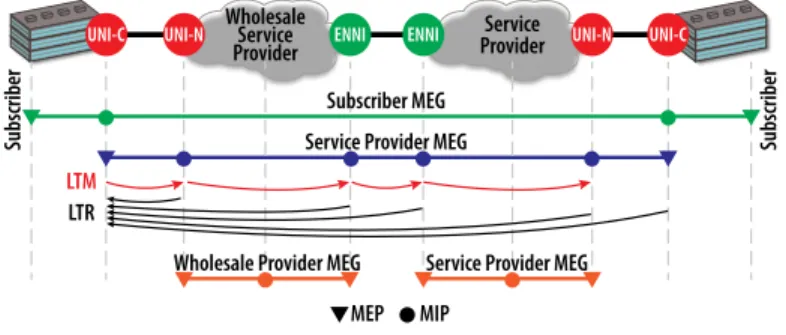
Link trace is similar to ICMP traceroute used for IP networks, but is performed at Layer 2. Link trace sends out an LTM across an EVC or OVC. At each MIP or MEP along the EVC or OVC, an LTR is returned to indicate that at the MIP or MEP along the EVC or OVC was reachable and capable of responding. Refer to Figure 30.
Service Provider Wholesale
Service
Provider UNI-C
UNI-C UNI-N ENNI ENNI UNI-N
Subscriber MEG Service Provider MEG
Subscriber Subscriber
Wholesale Provider MEG MEP
LTM
LTR
MIP
Service Provider MEG
Figure 30: Link Trace Example
Link trace is used to determine where a fault has occurred along an EVC or OVC path, at which point an LTR message would not be received. This enables network operations personnel to precisely determine an EVC or OVC fault location. Once a fault is isolated, Ethernet link fault management tools can be utilized to further interrogate the connection between Ethernet ports.
Summary
Carrier Ethernet augments the familiar and ubiquitous Ethernet LAN technologies to build metro and wide-area networks. Carrier Ethernet is used to build network infrastructure and deliver retail and wholesale communications services. Carrier Ethernet building blocks include the Ethernet UNI and ENNI, which provide service demarcation between buyers and sellers of services, while EVCs and OVCs define the virtual connectivity between these interfaces.
The MEF defined Ethernet service types based on their connectivity and Ethernet services by how the UNI supports either one service (port-based, such as EPL), or multiple services (VLAN-(port-based, such as EVPL). Finally, Ethernet OAM is critical for service providers to deliver and maintain mass-market Ethernet services. Ethernet service attributes, such as bandwidth profiles and service multiplexing, enable differentiation so that service providers can deliver standardized, yet highly customizable services.
Acronym Definition
ATM Asynchronous Transfer Mode CBS Committed Burst Size CCM Continuity Check Message CFM Connectivity Fault Management CIR Committed Information Rate CLE Connectionless Ethernet
CM Color Mode
CoS Class of Service
DSCP Differentiated Services Code Point E-Access Ethernet Access service type EBS Excess Burst Size
EIR Excess Information Rate E-LAN Ethernet LAN service type E-Line Ethernet Line service type
ENNI External Network-to-Network Interface EPL Ethernet Private Line service
EP-LAN Ethernet Private LAN service EP-Tree Ethernet Private Tree service E-Tree Ethernet Tree service type EVC Ethernet Virtual Connection EVPL Ethernet Virtual Private Line service EVP-LAN Ethernet Virtual Private LAN service EVP-Tree Ethernet Virtual Private Tree service GFP Generic Framing Procedure ICMP Internet Control Message Protocol
IEEE Institute of Electrical and Electronics Engineers
IP Internet Protocol
ITU International Telecommunications Union LAN Local Area Network
LOAM Link OAM
LTM Link Trace Message
Acronym Definition
LTR Link Trace Response MA Maintenance Association MAN Metropolitan Area Network
MBH Mobile Backhaul
MEF Metro Ethernet Forum MEG Maintenance Entity Group MEP Maintenance Endpoint
MIP Maintenance Intermediate Point MP2MP Multipoint-to-Multipoint MPLS Multiprotocol Label Switching
OAM Operations, Administration and Maintenance OTN Optical Transport Network
OVC Operator Virtual Connection
P2P Point-to-Point
PBX Private Branch Exchange PDH Plesiochronous Digital Hierarchy PCP Priority Code Point
PPP Point-to-Point Protocol RMP Rooted Multipoint SLA Service-Level Agreement SLO Service-Level Objectives
SOAM Service OAM
SONET Synchronous Optical Networking TDM Time-Division Multiplexing UNI User-to-Network Interface VoIP Voice over IP
VPLS Virtual Private LAN Service VPN Virtual Private Network
WAN Wide-Area Network
WDM Wavelength-Division Multiplexing
© Copyright 2010 Fujitsu Network Communications Inc.