Name Designation Affiliation Date Signature
Submitted by:
TJ Stevenson System Engineer SPDO 2011‐02‐14
Approved for release as part of SKA System dCoDR documents:
K. Cloete Project Manager SPDO 2011‐02‐14
SYSTEM
ENGINEERING
MANAGEMENT
PLAN
Document
number
...
WP2
‐
005.010.030
‐
MP
‐
001
Revision
...
F
Author
...
T.J.
Stevenson
Date
...
2011
‐
02
‐
14
Status
...
Approved
for
release
Revision : F
2011
‐
02
‐
14
Page 2 of 52DOCUMENT
HISTORY
Revision Date Of Issue Engineering Change
Number
Comments
A 2009‐03‐27 ‐ First draft release for internal review
B 2009‐04‐08 ‐ Update following high level internal review.
C 2009‐04‐14 ‐ Small formatting changes. Issued for IEAC meeting.
D 2010‐01‐20 ‐ Updated following the review of Rev C by the SEDG.
Changes are captured in COAR:
WP2‐005.010.030‐OAR‐001‐D
E 2010‐02‐02 ‐ Updated with the comments received on Rev E up to and
including 2010‐02‐02. Released for system CoDR.
F 2011‐01‐31 ‐ Updated section 6.5.1 with review process, updated
figures 1 and 10, updated section 7. Released for dCoDR.
DOCUMENT
SOFTWARE
Package Version Filename
Wordprocessor MsWord Word 2007 WP2‐005.010.030‐MP‐001‐F_SKASEMP
Block diagrams MsVisio Visio 2007 SEMP (Rev F) Drawings.vsd
COMPANY
DETAILS
Name SKA Program Development Office Physical/Postal
Address
Jodrell Bank Centre for Astrophysics Alan Turing Building
The University of Manchester Oxford Road Manchester, UK M13 9PL Fax. +44 (0)161 275 4049 Website www.skatelescope.org
2011
‐
02
‐
14
Page 3 of 52TABLE
OF
CONTENTS
1
INTRODUCTION ... 6
1.1 Purpose of the document ... 6 1.2 Scope of the document ... 62
REFERENCES ... 6
2.1 Applicable documents ... 6 2.2 Reference documents ... 63
INTRODUCTION ... 7
3.1 What is System Engineering and Why is it Important to the SKA ... 8 3.2 Project Phases and Transitions ... 11 3.3 General System Engineering Philosophy ... 114
SYSTEM ENGINEERING PROCESS PLANNING ... 12
4.1 Organisational Responsibilities and Relationships ... 12 4.2 Integration of the global System Engineering Effort ... 13 4.3 System Hierarchy ... 14 4.4 Major Deliverables ... 18 4.4.1 PrepSKA ... 18 4.4.1.1 Documentation ... 18 4.4.1.2 Repository ... 19 4.4.1.3 Engineering Baselines ... 19 4.4.2 Phase 1 ... 20 4.4.3 Phase 2 ... 20 4.5 Technical Objectives ... 20 4.6 Standards and Procedures ... 21 4.7 Constraints ... 22
5
SYSTEM ENGINEERING PROCESS AND APPLICATION ... 22
5.1 Tailoring ... 22 5.2 System Engineering Process ... 22 5.2.1 User needs ... 22 5.2.2 Requirements Analysis and Validation ... 23 5.2.3 Functional Analysis, Functional Verification and Synthesis ... 26 5.2.4 Design Verification ... 27 5.3 Application of the System Engineering Process ... 28 5.3.1 Systems Engineering Phases and Engineering Baselines of the SKA ... 31 5.3.1.1 Concept Phase ... 31 5.3.1.2 Definition Phase ... 31 5.3.1.3 Preliminary Design Phase ... 32 5.3.1.4 Detailed Design Phase ... 33 5.3.1.5 Production ... 33 5.3.1.6 Site Integration and Testing ... 34 5.3.2 Notes ... 34 5.3.2.1 Testing, Verification and Acceptance ... 34 5.3.2.2 Software ... 36
Revision : F
2011
‐
02
‐
14
Page 4 of 52 5.3.2.3 Logistics and Support ... 36 5.3.2.4 Operations... 37 5.3.2.5 Phase 2 ... 376
CONTROL ... 37
6.1 Project Dictionary ... 37 6.2 Work Breakdown Structures ... 37 6.3 Interface Management ... 37 6.4 Data Management ... 38 6.5 Reviews and Audits ... 38 6.5.1 Technical Reviews ... 38 6.5.1.1 Basic principles ... 39 6.5.1.2 Review tasks ... 39 6.5.1.3 Review Descriptions ... 41 6.5.1.4 Concept Design Review (CoDR) ... 42 6.5.1.5 (Sub)System Requirements Review (SRR) ... 43 6.5.1.6 Preliminary Design Review (PDR) ... 43 6.5.1.7 Critical Design Review (CDR) ... 44 6.5.1.8 Production Review (PR) ... 44 6.5.1.9 Test Readiness Review (TRR) ... 45 6.5.1.10 Acceptance Review (AR) ... 45 6.6 Requirements Traceability ... 46 6.7 Risk Management ... 46 6.8 Baseline establishment ... 46 6.9 Configuration Management ... 47 6.10 Change Management ... 48 6.11 Logistics ... 48 6.12 Quality ... 497
TRANSITIONING HIGH RISK TECHNOLOGIES ... 50
8
A
DDITIONALS
YSTEME
NGINEERINGA
CTIVITIES... 51
8.1 Tools ... 51 8.2 Safety ... 51 8.3 Standardisation ... 51 8.4 Obsolescence ... 51 8.5 Human Engineering ... 51 8.6 Redundancy ... 52
LIST
OF
FIGURES
Figure 1: SKA Overall Flow. ... 9 Figure 2: SKA High Level Block Diagram. ... 10 Figure 3: SKA Project Iterative Process. ... 12 Figure 4a: SKA System Hierarchy. ... 16 Figure 5: The systems engineering process. ... 23 Figure 6: SKA user system context diagram. ... 24
2011
‐
02
‐
14
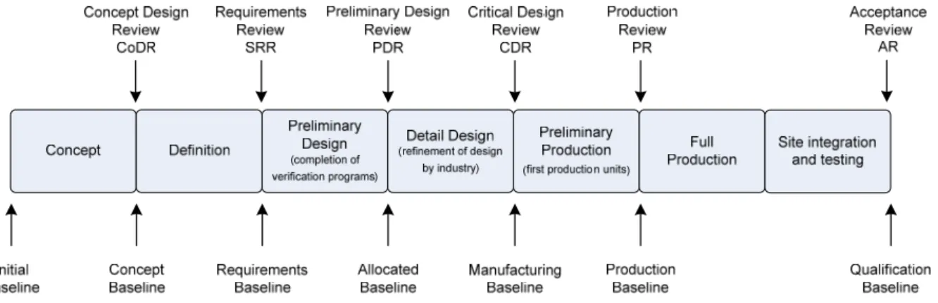
Page 5 of 52 Figure 7: Requirements analysis process. Numbers refer to paragraphs in [7]. ... 25 Figure 8: Functional analysis process. Paragraph numbers are from [7]. ... 27 Figure 9: System engineering phases, reviews and baselines. ... 29 Figure 10: SKA1 typical system life cycle phases and reviews. ... 30 Figure 11: Narrowing of options during first three phases. ... 32 Figure 12: Roll out utilising integration test facilities. ... 36 Figure 13: Review information flow ... 40 Figure 14: OAR Worksheet processing ... 41 Figure 15: Technology decision points. ... 50LIST
OF
ABREVIATIONS
AAVP ... Aperture Array Verification
Program
APERTIF ... APERture Tile In Focus
AR ... Acceptance Review
ASKAP ... Australian Square Kilometre Array
Pathfinder
ATP ... Acceptance Test Procedure
ATR ... Acceptance Test Result
BIT ... Build In Test
CCB ... Configuration Change Board
CDR ... Critical Design Review
COAR ... Consolidated Observation Action
Register
CoDR ... Concept Design Review
DRM ... Design Reference Mission
EMBRACE ... Electronic MultiBeam Radio
Astronomy ConcEpt
EMC ... Electromagnetic Compatibility
EVLA ... Expanded VLA
FAT ... Factory Acceptance Test
FCA ... Functional Configuration Audit
GLAST ... Gamma‐ray Large Area Space
Telescope
HPC ... High Performance Computing
IEC ... International Electrotechnical
Commission
IEEE ... Institute of Electrical and
Electronics Engineers
ICD ... Interface Control Document
INCOSE ... International Council on Systems
Engineering
ISO ... International Standards
Organisation
KAT ... Karoo Array Telescope Project
km ... Kilometre
LEMP ... Logistic Engineering Management
Plan
LOFAR ... Low Frequency Array
LWA ... Long Wavelength Array
MeerKAT ... The precursor array being build on
site in the Karoo
MIL‐STD ... Military Standard
NASA ... National Aeronautics and Space
Administration
NRAO ... National Radio Astronomy
Observatory
OAR ... Observation Action Register
OICD ... Operator Interface Control
Document
PCA ... Physical Configuration Audit
PDR ... Preliminary Design Review
PPR ... Pre‐production Review
PrepSKA ... Preparatory phase for the SKA
RAM ... Reliability, Availability and
Maintainability
Rev ... Revision
RFI ... Radio Frequency Interference
RSP ... Reference Science Plan
SAT ... Site Acceptance Test
SEMP ... System Engineering Management
Plan
SKA ... Square Kilometre Array
SKADS ... SKA Design Studies
SPDO ... SKA Program Development Office
SRR ... (Sub)System Requirements Review
SSEC ... SKA Science and Engineering
Committee
STaN ... Signal Transport and Networks
TBC ... To be confirmed
TBD ... To be determined
TDP ... Technology Development Program
TRR ... Test Readiness Review
VLA ... Very Large Array
WBS ... Work Breakdown Structure
WP2 ... PrepSKA Work package 2
Revision : F
2011
‐
02
‐
14
Page 6 of 521
Introduction
1.1
Purpose
of
the
document
The Square Kilometre Array (SKA) project has been ongoing for several years and has now reached a stage where many engineering activities will be conducted in parallel at various levels of the project spread across the globe at many contributing institutions and companies. It is therefore of the utmost importance that a coherent system engineering approach and focus be created early in the project and be maintained throughout the life cycle of the project.
The purpose of this System Engineering Management Plan (SEMP) is therefore to provide the framework and guidance for all engineering activities within the overall SKA project.
1.2
Scope
of
the
document
This System Engineering Management Plan (SEMP) will describe the approach, activities, products,
processes, tools and controls that will be used during the relevant phases of the project to support
and eventually ensure the successful development, deployment and commissioning of the SKA
telescope, including maintenance and support capabilities, on the selected site.
This SEMP is a living document and will be updated at regular intervals to reflect changes and progress.
2
REFERENCES
2.1
Applicable
documents
The following documents are applicable to the extent stated herein. In the event of conflict between the contents of the applicable documents and this document, the applicable documents shall take precedence.
[1] None
2.2
Reference
documents
The following documents are referenced in this document. In the event of conflict between the contents of the referenced documents and this document, this document shall take precedence:
[2] R.T. Schilizzi et al., ‘Memo 100 – Preliminary Specifications for the Square Kilometre
Array’, dated December 2007.
[3] P.E. Dewdney, ‘Guiding Principles, Activities and Targets for PrepSKA Work Package 2’, Version 2.4, dated 2 November 2008.
[4] R.T. Schilizzi, P.E. Dewdney and C. Greenwood, ‘Project Management Plan for the
Square Kilometre Array, 2008‐2012’, Reference SSEC 080723‐9.3a, Draft v1.6, dated 17
July 2008.
[5] P.E. Dewdney, ‘SKA Science‐Technology Trade‐Off Process’, WP2‐005.010.030‐MP‐004, Rev 1.1, dated 2010‐01‐20.
[6] K. Cloete, ‘Risk Management Plan’, document MGT‐040.040.000‐MP‐001, Rev 1, dated
2011
‐
02
‐
14
Page 7 of 52[7] ISO/IEC 26702 (IEEE Std 1220‐2005), ‘Systems engineering – Application and
management of the systems engineering process’, dated 9 September 2005.
[8] INCOSE Publications, ‘Systems Engineering Handbook – A guide for system life cycle
processes and activities’, V3.1 dated August 2007.
[9] T. Thurston and W. Davis, ‘Gamma‐ray large area space telescope (GLAST) ‐ Large area
telescope (LAT) ‐ Systems engineering management plan’, document number
LAT‐MD‐00066‐01, 3rd draft dated 23 January 2001.
[10] K. Cloete, ‘PREPSKA Documentation Standards, Handling and Control’, document
number MGT‐040.010.010‐MP‐001, Rev C, dated 2009‐04‐02.
[11] D. Liebenberg, ‘SKA Logistic Engineering Management Plan (LEMP)’, document number WP2‐005.010.030‐MP‐002, Rev C, dated 2010‐01‐18.
[12] P. Dewdney et al., “SKA‐Phase 1: Preliminary System Description”, v2.1, SKA Memo 130, Nov. 2010.
[13] M.A. Garrett, J.M. Cordes, D. De Boer, J.L. Jonas, S. Rawlings, and R. T. Schilizzi (SSEC SKA1 Sub‐committee), “Concept Design for SKA1 (SKA1)”, SKA Memo 125, Aug. 2010.
3
Introduction
An overall high level schedule for the Square Kilometre Array (SKA) project is shown in Figure 1 and it can be seen that the project is currently within the Preparatory SKA (PrepSKA) phase. During the preceding years many working groups and task forces have been active across the globe defining and refining the SKA science and engineering. This has resulted in the publication of many documents and memos forming a solid base from which PrepSKA could be launched.
One of these memos, Memo 100 [2], captured and presented the baseline design of the instrument. During the review of this document by the SKA Specification Review Committee it was suggested that a reference science mission be developed against which this design could be measured. This lead to the development of the Design Reference Mission (DRM) (formerly known as the Reference Science Plan (RSP)) which has official release status. From the platform and baseline established by
these two documents (Memo 100 and DRM) the work for the next few years will move forward to
the eventual goal of delivering a fully costed system design by the end of PrepSKA.
Against the background of the proposed ‘full’ SKA, a subset has been proposed as a Phase 1. This SEMP equally applies to this first stage programme and has not been tailored.
It is foreseen that during this process several iterations between science and engineering will take place and that other important inputs to the overall system design such as the operations, support and environmental studies, to name but a few, will be developed, refined and brought into the design effort.
The current high level SKA block diagram is shown in Figure 21. As presented in this figure the SKA
will not only consist of very many elements and subsystems, it will be physically spread out across
thousands of kilometres on the selected site and even across the globe. This aspect together with
the fact that the design work is spread around the globe as well, makes the adoption of a coherent system engineering view on the project critical to its success. It is in this context that this Systems Engineering Management Plan (SEMP) has been developed.
1
Note that Figure 2 does not represent any design decisions. Trade‐offs still have to be performed and location
Revision : F
2011
‐
02
‐
14
Page 8 of 523.1
What
is
System
Engineering
and
Why
is
it
Important
to
the
SKA
For a project as large and complex as the SKA, the adoption and execution of a systems engineering approach is a requirement and not an option. Examples are spread throughout industry, military and large science projects where the systems engineering approach has been adopted and is being used with great success, but the question might remain – what is systems engineering?
Numerous definitions of System Engineering are in existence. Examples are:
a) Systems engineering is the art and science of developing an operable system capable of meeting requirements within often opposed constraints. Systems engineering is a holistic, integrative discipline, wherein the contributions of structural engineers, electrical engineers,
mechanism designers, power engineers, human factors engineers, and many more
disciplines are evaluated and balanced, one against another, to produce a coherent whole that is not dominated by the perspective of a single discipline. (Extract from NASA Systems Engineering Handbook, NASA/SP‐2007‐6105, Rev1)
b) Systems engineering is an iterative process of top‐down synthesis, development, and
operation of a real‐world system that satisfies, in a near optimal manner, the full range of requirements for the system. (Extract from INCOSE Systems Engineering Handbook, Rev 3.1) In summary it can be said that systems engineering is a balanced and iterative approach aimed at the eventual successful realisation and operation of systems by ensuring the inclusion of the full spectrum of requirements and engineering disciplines and with a continuous view of the total life cycle of the system.
The ability to influence the final life cycle costs of any system is particularly significant during the early stages of the project. As the project progresses the decisions or even worse, the non‐
decisions, which were made or not made upstream, will impact the project downstream. It has been shown that the costs associated with implementing changes late in a project can be orders of magnitude greater than the cost that would had been incurred have the change been implemented early on in the process. Changes are of course not only limited to mistakes that have been made, but also include the late addition of requirements to the system due to aspects that were forgotten or neglected at the start of the project or even the removal of requirements and features. It is within this context that the strength and importance of the systems engineering approach can be found. With all of this in mind and taking into account that the SKA is a highly complex, large and very distributed (in terms of institutions and work being performed) project, the successful adoption and roll out of a systems engineering approach within the project is of critical importance. The process will not only attempt to have the upfront work done very well, it will guide and control the work to be done during subsequent phases at all the levels of the project all the way through to the disposal phase of the project.
2011‐02‐14 Page 9 of 52
Figure 1: SKA Overall Flow. Preliminary
Design
Concept definition Sub-System Definition Detailed
Design Site Assembly, Integration and Testing
Preliminary Design
CoDR SRR PDR
repor
t
RFI Monitoring
Site Acceptance tests including RFI qualification
Site Engineering Dishes Signal Processing Imaging Concept
Software Requirements Definition
Preliminary high level architecture On-site Testing
Phase 1 Refinement and Roll-out CoDR PDR Software & Computing Signal Transport & Networks Sub-System Definition CoDR PDR CDR CDR RQZ Site characteristics Atmospheric studies Configuration studies CDR
Remote Station Land Acquisition & Environmental Studies Continued RFI and Tropo Monitoring
Temporary Software Correlator
SKA2 Continuation SKA2 Continuation
SKA2 Signal Processors Definition and Design
Monitoring & Control Data Storage
CDR
PR
SRR
Hardware Early Fabrication
PR
Factory Assembly, Integration and Testing Site Assembly, Integration and Testing
SRR
PDR
Front End and Channeliser Beamformer and Correlator Pulsar and Transient Processor
Refine high level architecture Preliminary Design
Ops and Maintenance Facility Purchase
or Fab
Detailed Design
Detailed Design, Coding, Integration with platforms
and testing
Central Data Processing Facility Science Computing Facility
Factory Assembly, Integration and Testing
Rev 9 2011-02-14
Concept Phase 1 System Testing
SRR
System CoDR
SKA1 Systems integration
PDR CDR
Phase 1 Verification and Commisioning
Detailed Design
Final SKA Deployment Plan
Project management
PM Plan & Schedule SKA Scope definition
PrepSKA Plan
Project staffing & development WBS, resource allocation
CoDR PDR CDR
REV REV
Science DRM Development
Revision of Science Case
REV
Refinement of Early Science Shared Risk Science Operations
REV
SKA2 Science Development
REV REV
Science / Engineering tradeoffs
Early Science Proposals
Continuous Performance Evaluation
Project execution, monitor and control Infrastructure Detailed Design (fibre & power)
Antenna Foundations and Trenching Roll out Infrastructure Detailed Design (buildings) CDR AA-low PDR SRR CoDR CDR Preliminary Design Definition Concept SKA1 SKA2
Continued SKA1 SE/Change management
dCoDR
Definition and high level Preliminary Design Preliminary Design
PDR Detailed Design Detailed Design Preliminary Design Definition Concept
Site Assembly, Integration and Testing Tooling and Early
Fabrication
Factory Assembly, Integration and Testing
CoDR SRR PDR CDR PR
Detailed Design Preliminary Design
Definition Concept
Site Assembly, Integration and Testing Tooling and Early
Fabrication
Factory Assembly, Integration and Testing
PR
DVA1Development and Fabrication DVA1 Testing DVA2 development and testing
AAVS1 Testing
AAVS1 Development and Fabrication AAVS2 development and testing
Demonstration and testing AIP definition, development and fabrication
AIP PAF or AA-mid Preliminary Design
PAF or AA-mid Detailed Design
SKA2 PDR
Phase 2 Infrastructure Definition and Design
SKA2 STaN Definition and Design
SKA2 Software Design SKA2 Design Confirmation SKA2 Design Confirmation
Revision : F
2011‐02‐14 Page 10 of 52
Figure 2: SKA High Level Block Diagram.
SKA
Conceptual
Block
Diagram
Regional Science Centre(s) Regional Engineering Centre(s) Science Computing Facility Outlying Station Outlying Station Outlying Station Outlying Station Outlying Station Dense Aperture Array Operations and Maintenance Centre Signal Processing Facility On Site SKA HQ (Off Site) GlobalHigh Performance Computing Data Storage Digital Signal Processing
Beamforming Correlation SKA Conceptual High Level Block Diagram Drawing number : TBD Date : 2009-02-13 Revision : E Outlying stations on spiral arm (only one arm is
shown) Wide band single pixel feeds (WBSPF) Phased array feeds (PAF) Dish Array High Low
2011‐02‐14 Page 11 of 52
3.2
Project
Phases
and
Transitions
The SKA project has been subdivided into various phases as shown in Figure 1. Although the transitions between the phases are shown as single points or events in time, these transitions will, in practice, overlap with the next phase starting before the preceding phase has been completed. This is important because, for each phase of the project, the systems engineering process activities and requirements differ. Work will therefore be conducted concurrently as the phases overlap, and good management and control of these activities will be essential. The primary construction phases of the project are Phase 1 and Phase 2. These are separate phases imposed mainly due to funding reasons. They also serve to reduce risk: Phase 1 will serve as a final confirmation of the production baseline before the larger roll‐out of equipment in Phase 2 commences. Phase 2 can therefore be seen as a continuation of Phase 1 but at an escalated rate of production. Phase 2 will, however, be different in two key areas. The first being the fact that the roll‐ out of equipment on site will escalate with resulting increase in installation, acceptance, integration,
commissioning and support requirements. Throughout the PrepSKA design activities this escalation
requirement will be taken into account and will form part of the final PrepSKA deliverables. The PrepSKA deliverables will include plans, activities and costs for scaling the project from Phase 1 to Phase 2 and will include aspects such as acceleration in the production of hardware, the increase in personnel both on site and off site, scaling and expansion of infrastructure etc.
The second difference between Phase 1 and Phase 2 is the fact that the Phase 1 instrument will be utilised for early science work while the construction of Phase 2 will be continuing around it. Clear plans, strategies and processes will be developed during the PrepSKA activities to ensure that the requirements for this transitioning are well thought through and form part of the eventual design of the system, especially that of Phase 1.
In the event that there is significant introduction of improved technology between Phases 1 and 2 (necessitating the obsolescence of major parts of the system) the details of the Plan will be changed to reflect the necessary increase in qualification and verification activity.
Also shown on Figure 1 is the proposed system engineering phases at the user system level and at element level and their relative alignment with the project phases and other milestones. The details of the system engineering phases are described later in this document.
3.3
General
System
Engineering
Philosophy
Because the SKA, as defined in [2], is a combination of very complex technologies of which many are not mature, the risks that the project will be facing are high. A rigorous single pass top down system engineering philosophy in this kind of environment will therefore not deliver the optimum solution and eventual successful implementation and roll out of the SKA system. The model that will be adopted will lean more towards the spiral approach whereby requirements and potential solutions and designs are iterated and refined. This approach supports the philosophy as put forward in [3]. However, it must be emphasised that although a spiral model is adopted, the steps within the system engineering process (as described in paragraph 5) must still be executed faithfully and comprehensively.
A graphical representation of the iterative process is given in Figure 3. From the Observatory level the iterations and trade‐offs will be strongly linked to the science requirements. The underlying theme for the sequence of all the design reviews is to create a system design for the full SKA, with
well‐understood cost, commensurate with maximizing science return. Top‐level Observatory
Revision : F
F
2011‐02‐14 Page 12 of 52
captured in the Design Reference Mission. These case studies have been selected to form the upper
“envelope” of science requirements. A method for objectively carrying out the necessary science‐
technology trades has also been developed (see [5]). The method is based on the performance, cost and risk of the relevant technologies and the science return of the relevant science areas. The process of making the trades will be carried over time and expressed as a gradual narrowing of options as the system design reviews progress. Performance, cost, risk and science return will underlie the deliberations at each review stage.
Because of the iterative nature the work to be done will include refinement of technologies and requirements at the subsystem level, which will provide feedback and inputs to the element and system levels of the project. A good example of this process is the dish verification program. These inputs from the lower levels will also be utilised in the trade off studies and eventual refinement of the system level requirements and design. Refined requirements will be re‐allocated back to the lower levels and the iteration will be repeated. At different levels the iterative process may be repeated more than once.
The primary output of the process by the end of PrepSKA will be a fully defined and costed system design supported by defined and costed elements and subsystems.
The fact that the system engineering process is concurrent at a number of levels will provide numerous challenges and pitfalls. Discipline will have to be maintained throughout the process in terms of documentation development, reviews, standards, quality, traceability and the other requirements as set out in this plan. This will be applicable to hardware as well as software developments.
The process will start at the defined baseline of Memo 100 [2] and the DRM. Other groundwork performed thus far will also be utilised but care must be taken to ensure that the gaps that currently exist in this work are identified and are addressed.
Figure 3: SKA Project Iterative Process.
4
System
Engineering
Process
Planning
4.1
Organisational
Responsibilities
and
Relationships
The organisational responsibilities have, to a large extent, been set out in detail in documents [3] and [4]. In summary the SKA Program Development Office (SPDO) has domain specialists in various fields that will, under direction of the SKA Project Engineer, plan and lead the activities within each domain. Each of these domain specialists will be responsible for the implementation and execution
2011‐02‐14 Page 13 of 52
of the system engineering activities for hardware and software within his/her domain. They will ensure that the system engineering approach flows down into the relevant lead and supporting institutions to an acceptable level and detail to support the overall system engineering effort.
All verification programs will adhere to the methodology and philosophy as described in this document. It is expected that each of the verification programs will be led by a system engineer and/or a project engineer or the relevant SPDO domain specialist. In cases where the activities are not led by the SPDO domain specialists the relevant system/project engineer will be clearly identified and will form part of the System Engineering Group to ensure integration and coherence of the verification program with the overall SKA system engineering effort.
4.2
Integration
of
the
global
System
Engineering
Effort
The global effort outside the SPDO has been divided into the following three categories (as approved by the SSEC):
Precursor: A telescope on one of the two candidate sites which includes ASKAP, MeerKAT and MWA.
Design Study: A study of one or more major sub‐systems of the SKA design, including the construction of prototypes and includes the Canadian SKA Program, TDP, SKADS and AAVP. Pathfinder: SKA‐related technology, science and operations activity and includes LOFAR,
EMBRACE, APERTIF, LWA, ATA and EVLA.
To establish and ensure a coherent system engineering approach and coordinated efforts within and across the levels of the SKA project, a System Engineering Group, lead by the SPDO Systems Engineer, will be established. Attempts will be made to include as much as possible of the global activities and groups, as set out above, in the System Engineering Group.
The proposed members of this group are:
SPDO Project Engineer
SPDO System Engineer
SPDO Domain Specialists for Receptors, Signal Transport and Networks, Digital and
Computing and Software (at least during the initial stages) SPDO Site Engineer (WP3) AAVP Project Engineer and AAVP System Engineer ASKAP and MeerKAT project/system engineers NRAO representative(s) Pathfinder representatives (to be confirmed)
Although WP3 is a separate PrepSKA work package, the work and outputs from this work package
will influence the design of the SKA significantly and therefore need to be included and integrated
into the SKA system engineering effort.
Although the precursor arrays are, to a large extent, aimed at the development of instruments in their own right, a significant amount of work that will be performed as part of the precursor array(s)
Revision : F
F
2011‐02‐14 Page 14 of 52
development are relevant to the SKA. Inclusion of the precursor array system/project engineers within the System Engineering Group will aid continuous and effective communications between the SKA effort and the precursor arrays. It will be the responsibility of the precursor array system/project engineers to ensure that information and documentation relevant to the SKA effort produced specifically for, or as part of the precursor development, and especially site specific studies and designs, be made visible and available to the SPDO System Engineer for information and in support of the SKA design activities.
Interactions with the pathfinders will have to be strengthened. It is not proposed at this stage that all the pathfinder system/project engineers form part of the System Engineering Group but regular contact, interaction and especially information exchange will have to take place. Details of how this interaction will be established are TBD.
It must be emphasised that the main focus of the System Engineering Group will be the design aspects of the SKA at system and user system level. Although not all the members as listed above are directly involved in the SKA effort (for example the NRAO representatives), they are included because of their extensive experience with array development which will be very valuable as input to the SKA effort. It is foreseen that the System Engineering Group will meet quite regularly during the initial period of the PrepSKA phase in order to create a solid system engineering foundation early on in the project. Meetings will be conducted primarily via tele‐conferences but face to face interactions and meetings of this group will have to take place to focus on and discuss system and system engineering issues within the project. In addition it is strongly recommended that SPDO domain specialists be invited to participate in design reviews of the precursor, design study prototypes (such as the A3IV) and other pathfinder design reviews to enhance the communication of relevant design knowledge to the SKA project.
Each of the SPDO domain specialists will set up an SKA Engineering Design Group within their domain and lead and coordinate the activities and discussions within those groups. Although these meetings will focus heavily on technical issues within the domain, time will need to be allocated to discuss the system engineering issues within the domain on a regular basis.
4.3
System
Hierarchy
In order to structure the system engineering effort a system hierarchy will be developed and the first draft proposal of this hierarchy is shown in Figure 4 (a and b).
The project will be divided into several levels (layers). Within each of the levels there are various building blocks and each of these are linked to higher and lower level building blocks. For example – the eventual SKA User System (level 7) consists of the telescope, people and facility systems at level 6. In turn the telescope will consist of the dish array, sparse aperture array (high and low), dense aperture array, signal processing, signal transport and networks, computing and software, power and site infrastructure elements at level 5.
The hierarchy is a first step in the establishment of the system view of the project and is intended to provide a clear and coherent view on the scope and composition of each of the building blocks and of the system as a whole.
The hierarchy will also facilitate better communication and understanding and aligns terminology throughout. It provides a clear view of where requirements for each of the blocks originate and how the flow down of the process will be achieved.
2011‐02‐14 Page 15 of 52
Some of the implications of the hierarchy are:
Documentation will be developed for each of the building blocks within the hierarchy. For example ‐ a Requirement Specification for the dish array will be developed. This Requirement Specification will receive its inputs from the telescope system and will in turn allocate requirements to its major subsystems which in this example are the dishes, wide band single pixel feeds and phased array feeds.
Requirements traceability will follow the links between the building blocks and levels. For example the requirements for the sparse aperture array will trace its requirements to the telescope which in turn will trace its requirements to the user system.
The hierarchy also serves as a definition of responsibilities. Each building block has to be allocated to a person who will be responsible to ensure that the systems engineering work within that building block is being carried out in accordance with the top level SKA system engineering plan and procedures.
It will be possible to add or remove building blocks at any of the levels. However, there are various aspects that will need to be considered before this is done.
The hierarchy as shown is not intended to be the final version and is used as an example only. It is important to develop and agree on the hierarchy very early on in the project because not only will it will guide the system engineering effort of the project as a whole, it will form the basis for the system engineering work and products to be delivered at each level.
Aspects that will need to be considered during the tailoring of the hierarchy include a view on where the bases will be covered when any of the blocks are taken away and what is the view on the eventual testing and acceptance. For example – if it is foreseen that the dish array will be tested and accepted separately from other elements, it will be necessary to firstly have a dish array element and to develop a requirement specification for this array against which eventual testing and acceptance will be performed.
It is proposed that the hierarchy be reviewed within the Systems Engineering Group at the same time as the review of this SEMP.
Revision :
F
2011
‐
02
‐
14
Page 16 of 52
Figure 4a: SKA System Hierarchy.
2011
‐
02
‐
14
Page 17 of 52
Figure 5b : SKA System Hierarchy
Revision : F
F
2011‐02‐14 Page 18 of 52
4.4
Major
Deliverables
The eventual aim of the project is to deliver a cost effective, fully operational and fully supportable SKA user system. However, in achieving this aim the deliverables for the various phases will differ. Because of the uncertainty in the design of the full SKA the focus in this section will be on the deliverables for PrepSKA and some guidance will be provided for Phase 1.
4.4.1
PrepSKA
4.4.1.1 Documentation
Throughout the PrepSKA phase many studies, analyses, tradeoffs, specifications, interface control documents and other documents will be developed. Apart from this technical documentation an expected number of plans, standards, philosophies, reports and other management and technical artefacts will also be created. The end result will be a collection of many documents and as stated in [3], the legacy of PrepSKA will lie within this documentation.
The complete list of documentation to be developed during PrepSKA and beyond will not be listed
here. Some high level guidance on the technical documentation can be found as part of the description of each of the technical reviews. Details still have to be expanded and documents and document types will be refined. In general it can be stated that the documentation will include: A completed and agreed to design reference mission (DRM) A completed and agreed to science operations plan (SOP) A completed and agreed to maintenance and support plan (M&SP) Requirements specifications for each of the systems Designs for the systems Requirement specifications for all elements of the system Designs for all elements of the system Architectures for software elements Requirements specifications for all subsystems of the elements Designs for all subsystems of the elements Interface control definitions and interface designs at all levels Results of the tests performed on the verification models Scaling analysis (where applicable) Deployment plan Upgrade Plan Fully costed user system breakdown
2011‐02‐14 Page 19 of 52
In a few cases the activities will be taken down to part level and therefore detailed design documentation (such as mechanical design drawings) will be generated and be delivered as part of PrepSKA. With respect to the management, documentation guidance is provided in the Project Management Plan [4]. This includes the Project Book, Project Dictionary and Document Control Plan. Two aspects that need to be highlighted are the creation and upkeep of design files (part of the design documentation but not the complete design datapack) and the development of separate operator interface control documents.
The results from the studies, tradeoffs and analyses etc of the PrepSKA activities, will be utilised to
support decisions regarding requirements development and design. The documents, reports,
technical memo’s and other information developed and gathered as part of this process will be collected and recorded in design files. These design files will be managed at all levels and the main
custodians of these files will be the SPDO domain specialists (or project/system engineers in cases
where SPDO is not taking the lead) who will ensure that these files are generated and kept up to date.
To guide the development of the human machine interfaces, including operators, maintainers and
scientists a set of Operator Interface Control Documents (OICD) will be developed. These documents will provide guidance on screen layouts and operator interactions. Early development and review of these documents and mock‐ups will ensure that the user community is involved right up front and will greatly support and guide the development of human machine interfaces.
The PrepSKA documentation will not only underpin the costed user system design but will form the basis for the rest of the project. As a consequence, the documentation will have to be of high quality, complete and coherent. To achieve this goal, a number of supporting measures will be put into place including the establishment and utilisation of a repository of documentation and the establishment of baselines for each of the building blocks of the SKA. Each of these aspects is described in more detail in later paragraphs. It is furthermore proposed that a number of templates be created by the SPDO to be utilised throughout the project.
4.4.1.2 Repository2
A central repository for the project will be established and maintained by the SPDO. All documentation developed specifically for the SKA will be submitted to this repository. It is furthermore proposed that all supporting documentation collected also be captured within the repository. This will enhance traceability and form a reference basis for any further work.
A documentation handling guideline and procedure has been developed by the SPDO to guide activities in this regard [10].
It will be the responsibility of the SPDO domain specialists (or project/system engineers in cases where SPDO is not taking the lead) to ensure that the documentation developed within their domain is submitted to the repository on a regular basis and especially before and after baseline reviews.
4.4.1.3 Engineering Baselines
The evolution of each of the building blocks of the SKA will be defined in a series of baselines and baseline (technical) reviews (see paragraph 5.3.1).
2
Note that the word repository will be used throughout this document. It is, however, recognised that a
comprehensive Configuration Management System and related Configuration Management Plan will have to
Revision : F
F
2011‐02‐14 Page 20 of 52
These baselines will progress from high level down to the lower levels but will vary from element to element. However, following the establishment of a baseline at any hierarchical level the documentation will be ‘frozen’ for the particular baseline and changes thereafter will be more controlled. A more detailed description of the change management process can be found in paragraph 6.10.
To be able to successfully complete an engineering baseline, all the documentation as specified in
this SEMP3 will have to be presented during the review, reviewed, updated and submitted to the central repository. Failure to do so will result in a baseline being declared as not reached.
4.4.2
Phase
1
During Phase 1 it is foreseen that the work performed during PrepSKA will be taken further and the
documentation utilised as the base for this work. Additional documentation will be developed and
further life cycle baselines will be established down to the lowest level of the hierarchy.
Apart from the reviews several audits will be performed which will, in general, coincide with the technical reviews. Brief guidance on the audits is provided in paragraph 6.5.1.9. All of the documents created and generated during Phase 1 will be controlled and be submitted at regular intervals to the SKA document repository.
4.4.3
Phase
2
During phase 2 it is foreseen that the design utilised during the Phase 1 roll‐out will be refined and the production escalated to achieve the production capacities needed for Phase 2. Baselines will be updated and maintained very strictly during this phase. All of the documents created and generated during Phase 2 will be controlled and be submitted at regular intervals to the SKA document repository.
4.5
Technical
Objectives
The main technical objective of the PrepSKA WP2, as set out in [3] is:
“to produce a deployment plan for the full SKA, and a detailed costed system design for
Phase 1 of the SKA”
To achieve this it is important to realise that, as a subset of the full SKA, it will not be possible to design and cost Phase 1 without having a view on the full SKA design and cost.
In support of the PrepSKA WP2 objective a number of verification programs will be executed which are aimed at development of “standardised methods for verifying performance claims for key components” [3]. The intention of these verification programs is to reach a point where the applicability and feasibility of the relevant element or subsystem have been demonstrated and the design is captured to such a level as to be able to move forward into Phase 1 without major changes. Failure to reach this point may result in significant rework and delays to the overall project.
3 It will be possible to combine documents or to omit documents from a baseline review. However, these
2011‐02‐14 Page 21 of 52
The main aim of Phase 1 is firstly to refine the PrepSKA design documentation, build the first production units, develop the relevant software, integrate and perform standalone testing of these units, integrate all into a higher level and eventually roll out the entire Phase 1 instrument and relating support and people infrastructure on the selected site.
Depending on the progress and output from PrepSKA this strategy may change. This section of the document will therefore be updated as and when the strategy and philosophy of Phase 1 change.
4.6
Standards
and
Procedures
For the development of this document, two international system engineering standards were
utilised as guidelines ([7] and [8]) as well as the Gamma‐ray large area space telescope SEMP [9]. Although not prescribed for the SKA, it is highly recommended that both the international standards
be read by all because they provide a very good view of the systems engineering process for large
projects. During the course of PrepSKA the utilisation of other international standards and their applicability to the SKA will be investigated. Examples are: ISO software development standards (ISO/IEC 15288) Risk management (IEEE 1540) Quality management (ISO 9001) Logistics and support (DEF_STD_060, MIL‐STD‐1388‐2B and MIL‐STD‐1629A). Health and Safety (MIL‐STD‐882D, IEC 62061, IEC 61511 and various others) Electronic publications (AECMA 1000D) If found to be applicable and required, the standards will be introduced and made applicable to the project.
To aid in the alignment and coherency of the system engineering process, it is foreseen that a number of supplementary standards, philosophies and procedures will be developed internally to the project. Although not an exhaustive list it is foreseen that the following aspects will be included: Management and Control philosophy Self generated Radio Frequency Interference mitigation philosophy Built in Testing (BIT) philosophy Timing and synchronisation philosophy Logistic engineering standards and procedures Environmental standards Units of measure standards This list will be reviewed within the System Engineering Group for correctness and completeness and will be updated in accordance with the results of this review.
Revision : F
F
2011‐02‐14 Page 22 of 52
4.7
Constraints
Significant constraints in terms of time, focussed resources, the correct resources at the correct time, funding, technologies, to name but a few, are apparent, especially within the PrepSKA phase of the project. It is therefore recognised that it will not be possible to follow the full system engineering process as described in [7] and [8]. This SEMP therefore attempts to tailor this process to be able to focus on the important aspects and optimise documentation.
5
System
Engineering
Process
and
Application
5.1
Tailoring
Due to the constraints of time and resources faced, a tailoring of the process will be needed. Within this tailoring it is, however, not foreseen that steps within the process will be left out in their
entirety, it merely implies that the scope and formal outputs of the process at each step may vary
and that steps may be combined. The steps are important and skipping any one of them will result in a sub‐optimal system design and poor value for money.
5.2
System
Engineering
Process
The system engineering process as defined in [7] is shown graphically in Figure 5 and it is proposed that this process be adopted and applied within the SKA project. In general each of the activities shown in Figure 5 will be conducted at each of the levels of the hierarchy and during the specific phases of the project as the project moves through its lifecycle. As seen from the figure the activities are iterative and are being managed by the Control Process (which will be described later in this document) and it will be difficult or close to impossible to skip any of the steps.
To streamline the process it is proposed that steps and baselines be combined. In this regard the requirements analysis and validation will be combined and the results will typically be reflected in the requirement specification. The combination of the functional analysis, verification and synthesis will be captured in the relevant design documents while the documentation and data produced during the design verification will be captured in the design file. Short descriptions of the steps of the system engineering process are given below.
5.2.1
User
needs
To a certain extent the science user needs for the SKA user system are being captured in the Design Reference Mission (DRM). However, the scientists will not be the only ‘users’ of the system and it is foreseen that an analysis will have to be done in order to identify all the users (and stakeholders) of the system and to capture their needs. Translation of these needs into system requirements will be performed and will be flowed down the hierarchy to ensure influence on the design.
At each level of the hierarchy the user needs will have to be identified and formalised. To a large extent this will be in the form of the requirements allocated from the higher level and therefore this analysis will not be as extensive as at the user system and system levels.
2011‐02‐14 Page 23 of 52
Figure 5: The systems engineering process.
5.2.2
Requirements
Analysis
and
Validation
Understanding the requirements and making sure they are complete and stable are two of the most important aspects of the system engineering process because the rest of the activities are all based and derived from the requirements being developed during this step.
Requirements on the system or any part of the system, in this case the SKA, do not stem from the science requirements of the telescope alone. The science requirements are but one aspect, albeit important, of the overall requirement space. To illustrate this point a first order context diagram of contributors to the requirements of the user system is shown in Figure 6.
From this diagram it can clearly be seen that contributions to the eventual complete set of requirements of the user system and all its parts include inputs from a large number of stakeholders and different aspects. All these aspects need to be considered during the requirements analysis and development to ensure that the telescope will meet its performance requirements over its lifetime, in the environment in which it is deployed, supported, operated and maintained.
A graphical representation of the requirements analysis process as contained in [7] is shown in Figure 7. The process is quite complex and include a large number of activities. It is not proposed to follow the process exactly as indicated but note should be taken of all the components of the process to ensure that no gaps are left during the execution of the process. Comparing the context diagram shown in Figure 6 with the requirements analysis process shown in Figure 7 shows very close similarities.
Revision : F
F
2011‐02‐14 Page 24 of 52
Figure 6: SKA user system context diagram.
Up to this point in time the requirements for the SKA have been driven by science requirements. This is not necessarily a bad thing but it is important that the identification and influence of the other aspects on the user system, and therefore the elements and subsystems, be initiated as soon as possible and that these requirements become visible to the lower levels early on. To accomplish this it is proposed that the context diagram be reviewed and refined within the System Engineering
Group and that actions be identified to address the requirements development within each of the
blocks in the context diagram. As a continuous process, the context diagram and actions will be compared to the flow indicated in Figure 7 to ensure that no gaps are left. A similar process will be followed at the lower levels of the project but to a large extent requirements will be allocated from the higher levels implying a less intense requirement analysis phase. Health and Safety Regulatory Science Operations Maintenance and support Science Other Constraints (Virtual Observatory, VLBI, TOO interface, web
delivery interface) Natural Environment Technology System Human
factors Operators,Users, Scientists Security Existing Infrastructure Sources of interest External RFI Environment Academic and Science institutions
(Local and global)
Local communities and environment (cultures) Transitioning between phases Performing science operations while construction is proceeding Commercial Industry Power Providers
2011‐02‐14 Page 25 of 52
Figure 7: Requirements analysis process. Numbers refer to paragraphs in [7].
Input sources for the requirement gathering and analysis will include, amongst others, the outputs
from WP3, Task Force activities, Working Group activities, the Science Operations Plan, the Support Plan, interaction with manufacturers and industry, interaction with other radio and optical telescopes, etc. It is foreseen that specific aspects may require the establishment of Task Forces to assist and address these aspects in more detail (for example the current Power Investigation Task Force).
Because the verification programs will be initiated before the user system level requirements gathering, analysis and validation phases have been completed, a subset of requirements will be allocated to each program as a starting point. As the requirements on user system level mature these requirements will be flowed down and it is proposed that the status and impact of requirements be discussed during each review and progress meeting.
Revision : F
F
2011‐02‐14 Page 26 of 52
The process is iterative and as the verification programs and precursor, design studies and other
pathfinder arrays move forward they will provide feedback towards the user system and
requirements will be adapted and refined aimed at maximising science return. At the same time the verification programs will be gathering, analysing and validating their own requirements for eventual recording in the relevant requirement specifications.
Requirements validation is the process whereby the requirements that have been developed are validated against the original stakeholder expectations, user requirements and project constraints. The process will furthermore focus on the identification of gaps and to determine and confirm that the full spectrum of inputs has been taken into account and that the system will indeed be able to fulfil its full life cycle requirements.
The techniques that will be utilised for requirements validation include formal technical reviews, peer reviews, work group reviews, scenario studies, simulations and the building and testing of prototypes and verification models.
Throughout the process it will be important to record and write good requirements. A summary of good practice appears below.
5.2.3
Functional
Analysis,
Functional
Verification
and
Synthesis
The three steps of functional analysis, functional verification and synthesis are in essence the work to be done to arrive at the architecture or the design.
Functional analysis is the first step in the design process. It describes the problem defined by the
requirements in more detail and allocates functions and related perfomance to lower levels of the
design. A graphical representation of the functional analysis process as contained in [7] is shown in Figure 8.
Each of the activities is important to ensure completeness of the process and the eventual design. The end result of this process will be a functional architecture that is subject to a functional verification aimed at confirming the functional architecture and completeness of the architecture. Synthesis is the process whereby solutions for the functional architecture are investigated and elements and subsystems are identified. It translates the functional architecture into a design architecture. It is during this process that technologies and technology choices will play a role in the eventual design of the system (or element or subsystem). Other aspects such as the utilisation of off‐the‐shelf equipment and standardisation will also be addressed during this process.
To a very large extent the SKA elements and subsystems have already been defined and the design process is therefore not a blue sky search for design options. However, the functional analysis, verification and the allocation of these functions to the various elements and subsystems needs to be done to ensure that there are no gaps and that the elements and subsystems are able to perform the functions they are allocated. The combination of an already complete physical architecture and the combination of the three steps (functional analysis, verification and synthesis) will ensure that this part of the systems engineering process is as streamlined as possible.
Instruments to be utilised for the design process will include signal path analysis and block diagrams.