TROY Secure Print Enterprise Lite
Users Guide
TROY Secure Print Enterprise Lite Users Guide
TABLE OF CONTENTS Preface ... 3 Notice ... 3 Document History ... 4 Trademark Credits ... 5 Section 1 Introduction ... 6 Section 2 Installation ... 7Troy Secure Print Enterprise Lite installation steps: ... 7
Installation with Customized Configuration ... 10
Section 3 Printing ... 13
Section 4 TROY SecurePort Monitor Configuration Utility ... 14
Introduction ... 14
Selecting SecurePort Monitor ... 14
Saving Settings ... 14
TROYmark™ Tab ... 14
Pantograph Tab ... 14
Error Logging ... 14
Section 5 Printing the Pantograph ... 16
Introduction ... 16
Enabling the Pantograph ... 16
Configuring the Pantograph ... 17
Pantograph Pattern Adjustment ... 20
Section 6 Printing the TROYmark™ ... 22
Introduction ... 22
Enabling TROYmark™ ... 22
Configuring the TROYmark™ ... 23
Section 7 Adding New Secure Ports ... 25
Introduction ... 25
Add TROY SecurePort Utility ... 25
TROY Secure Print Enterprise Lite Users Guide
Preface
NoticeTROY GROUP, INC. MAKES NO WARRANTY OF ANY KIND WITH REGARD TO THIS MATERIAL, INCLUDING BUT NOT LIMITED TO, THE IMPLIED WARRANTIES OF MERCHANTABILITY AND FITNESS FOR A PARTICULAR PURPOSE.
TROY Group Inc. shall not be liable for errors contained herein or for incidental or consequential damages in connection with the furnishing, performance, or use of this material.
This document contains proprietary information that is protected by copyright. All rights are reserved. No part of this document may be photocopied, reproduced, or translated into another language without the prior written consent of TROY Group, Inc. The information contained in this document is subject to change without notice.
TROY Secure Print Enterprise Lite Users Guide
Document HistoryRevision Date Notes
1.0 July 2014 Initial release.
NOTICE
This document is the current edition of the TROY Secure Print Users Guide containing extensions to the PCL 5e printer language for the exclusive use of TROY Group Inc. and its assignees.
TROY Secure Print Enterprise Lite Users Guide
Trademark CreditsTROY, TROY SecureRx, and TROYmark™ are U.S. registered trademarks of TROY Group Inc. LaserJet, HP
and PCL are registered trademarks of the Hewlett Packard Company. Any other trademarks used within this
document are the property of their rightful owners, whether explicitly noted or otherwise.
TROY Interlocking Loop and Mortar and Pestle are registered trademarks of TROY Group Inc. See figures 1
and 2 below.
Figure 1: TROY on-demand pantograph with
Interlocking Loop design.
Figure 2: TROY on-demand pantograph with
Mortar and Pestle design.
TROY Secure Print Enterprise Lite Users Guide
Section 1
Introduction
Description
TROY Secure Print Enterprise Lite (TSPE) is a Windows-based software package created by TROY Group Inc. The main function of TSPE is to insert the TROY security print features into a print stream. TSPE acts as a virtual printer port. A user can print to TSPE just as they would to any Windows print queue. TSPE inserts the security features and then passes the print job on to the physical printer.
TSPE is an extension to the TROY SecurePort Monitor (TSM) application. The TSM without TSPE extension is only capable of inserting the commands to enable the security features on printers containing TROY printer firmware. The TROY firmware that resides in the printer adds the security features.
TSPE is capable of inserting the security features just as the TROY printer firmware does in a TROY printer. This makes TROY security features available on printers that cannot be modified with the TROY firmware. System Requirements
TSPE is built on the Microsoft .NET 4.0 Framework and therefore maintains the same System Requirements as .NET 4.0.
TSPE is now available for 64-bit operating systems. Two TSPE installation packages exist, one for 32-bit operating systems and one for 64-bit operating systems. The 64-bit version of TSPE will not run in a 32-bit operating system and the 32-bit TSPE will not run in a 64-bit operating system.
TROY Secure Print Enterprise Lite Users Guide
Section 2
Installation
Troy Secure Print Enterprise Lite installation steps:
1. Run TSPE InstallationTSPE installation package consists of an EXE file and up to two folders containing custom configuration and data. These folders are optional. If they exist in the same location as the EXE, the contents of these folders will be copied into the appropriate folders during installation. See the Installation with Customized
Configuration section below for more details. Run the appropriate EXE file to initiate the TSPE Installation Wizard.
2. Follow the TSPE Installation Wizard instructions
The installation wizard will step you through the installation process. The Installation Complete window will appear after a successful install.
Note: You will be prompted to download Microsoft .NET Framework 4.0 Client Profile if it has not already been installed. This will require a live internet connection and it may require a reboot after completion. The installation should restart automatically after the reboot. If the installation does not restart automatically, then return to step 1.
3. Create a new Windows print queue linked to the TROYPORT1: port monitor
To add a print queue, select Start Menu->Printers and Faxes or Start Menu -> Settings -> Printers. Select Add Printer and follow these steps in the Add Printer Wizard:
a. In the Local or Network Printer screen, select Local printer attached… and uncheck Automatically detect and install…
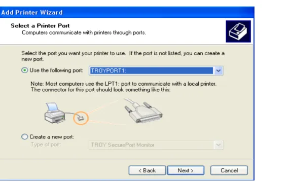
b. In the Select a Printer Port wizard screen, select Use Existing Port or Use the following port: and select TROYPORT1: from the drop-down list (see figure below).
TROY Secure Print Enterprise Lite Users Guide
Figure 2.1: Select a Printer Port screen showing TROYPORT1: selected.
c. In the Install Printer Software screen, select an HP PCL 5 driver for your model printer. PCL 5 drivers can be found on the TROY Group website
at http://www.troygroup.com/support/drivers.aspx.
d. In the Use Existing Driver screen (if it appears), select Keep existing driver (recommended). e. In the Name Your Printer screen, enter a name for the print queue such as TROY SecurePort
Monitor Printer 1.
f. In the Printer Sharing screen, select the appropriate choice for your system. g. In the Print Test Page screen, select “No”.
4. Create a Windows print queue connected to the printer (if it does not already exist)
Follow the steps from step 3 above to create a second print queue. For step b, select a Network, USB or LPT port connected to the printer. TSPE will use this print queue to direct the print job to the printer. The print queue can also be used by applications that do not need the TROY security features.
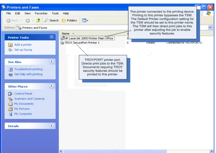
Figure 2.2 below shows the two print queues created in steps 3 and 4. One queue connected to TROYPORT1: and one connected to the Printer.
TROY Secure Print Enterprise Lite Users Guide
Figure 2.2: Two printer queues created in steps 3 and 4.
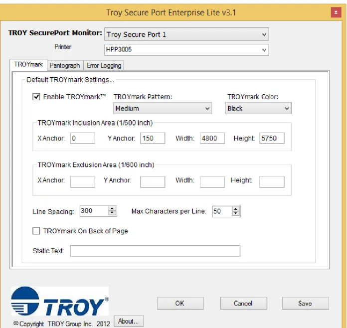
5. Set the Printer using the TROY SecurePort Monitor Configuration Utility
Run the Troy SecurePort Monitor Configuration Utility from the Start Menu under the TROY Group folder. Select Troy Secure Port 1 from the drop-down list at the top of the document. Set the Printer to the print queue created in Step 4 above. This is the print queue connected to the Printer.
TROY Secure Print Enterprise Lite Users Guide
Figure 2.3: Setting the default printer in the TSM Configuration Utility.
Installation with Customized Configuration
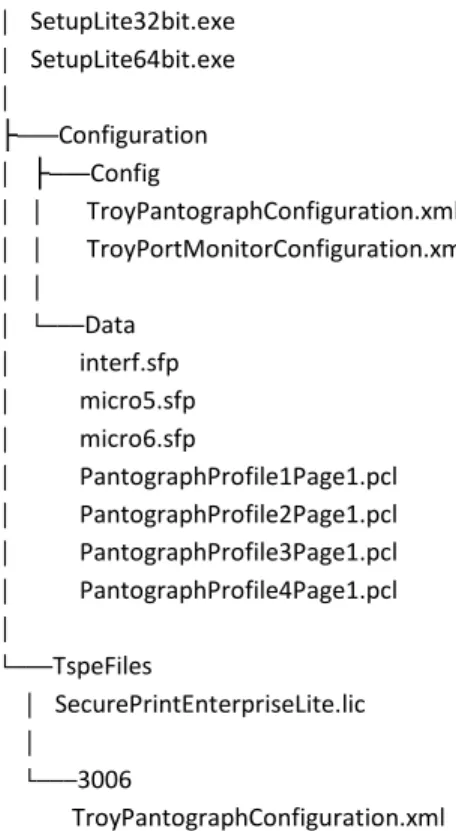
In addition to the setup EXE file, the TSPE installation can also contain configuration and data files stored in folders that reside in the same location as the setup EXE file. In the case of a clean installation, the folder names are Configuration and TspeFiles. In the case of an upgrade installation, only one folder is needed, namely ‘Port Monitor’. All names are case sensitive. Figure 2.4 below shows a typical installation folder containing these optional folders.
TROY Secure Print Enterprise Lite Users Guide
Clean Installation
Configuration Folder
The Configuration Folder can contain two subfolders named Config and Data. The contents of these folders will be copied to PrintPort1\Config and PrintPort1\Data as well as the Port Monitor\Configuration and Port Monitor\Data. The Config folder can contain one of two XML configuration files (TroyPortMonitorConfiguration.xml and
TroyPantographConfiguration.xml). The Data folder can contain any of the pantograph PCL files used to create the pantograph.
TspeFiles Folder
In the Quality Adjustment section below (Section 5), the concept of Baseline pantograph data files is explained. Different model printers require different pantograph configurations and quality adjustments. A baseline set of pantograph configuration files for each model printer can be included in the installation. The user can then configure a port with the baseline files for the model printer associated with the port. These baseline files are included in the installation in the TspeFiles folder. The name of the subfolders containing baseline files for specific model printers should contain the model printer name. These folders are copied to the Port Monitor\Baseline folder during installation.
Upgrade or re-installation
‘Port Monitor’ Folder
If you are upgrading or re-installing TSPE, you can have all of your settings re-applied at installation time. You can do this by creating a copy of the entire ‘Port Monitor’ folder prior to removing TSPE. By simply copying the ‘Port Monitor’ folder to the installation folder, all of your settings will be re-applied when you run the setup EXE. Please ensure that the ‘Port Monitor’ folder in the installation folder is named ‘Port Monitor’.
Including a License File in the Installation
A trial license or the live license file can be included in the installation. The license file should be placed in the TspeFIles folder. The license file will then be copied to the Port Monitor folder during installation.
Custom Installation Log
The installation creates a log containing details on the success or failure of adding the custom configuration files into the system. The log is located in the ‘Port Monitor’ folder. The name of the log is CustomInstallLog.txt. The log can be used to verify the success of the installation.
TROY Secure Print Enterprise Lite Users Guide
│ SetupLite32bit.exe │ SetupLite64bit.exe │ ├───Configuration │ ├───Config │ │ TroyPantographConfiguration.xml │ │ TroyPortMonitorConfiguration.xml │ │ │ └───Data │ interf.sfp │ micro5.sfp │ micro6.sfp │ PantographProfile1Page1.pcl │ PantographProfile2Page1.pcl │ PantographProfile3Page1.pcl │ PantographProfile4Page1.pcl │ └───TspeFiles │ SecurePrintEnterpriseLite.lic │ └───3006 TroyPantographConfiguration.xmlFigure 2.4: Example of an Installation with Custom Configuration Folders and Files.
TROY Secure Print Enterprise Lite Users Guide
Section 3
Printing
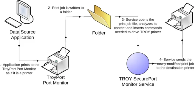
Figure 3.1 below shows the flow of a print job through the TSPE system. The document is first printed to the TROYPORT (the print queue created in Step 3 of the installation above). The print job is saved to a folder monitored by TSPE service. The service opens the print job file and makes adjustments to the print job file using information from configuration files. The print job is then sent to the printer defined in configuration.
Data Source Application TroyPort Port Monitor Folder TROY SecurePort Monitor Service
4- Service sends the newly modified print job to the destination printer 1- Application prints to the
TroyPort Port Monitor as if it is a printer
2- Print job is written to a folder
3- Service opens the print job file, analyzes its content and inserts commands
needed to drive TROY printer
Figure 3.1: Print job flow through TSPE system.
Printing without Troy Features
To print a document without TROY security features, print directly to the printer bypassing TSPE. This will prevent the commands for enabling TROY security features from being added to the print job.
TROY Secure Print Enterprise Lite Users Guide
Section 4
TROY SecurePort Monitor Configuration Utility
Introduction
The TROY SecurePort Monitor Configuration Utility (TSM Configuration Utility) can be used to adjust the
configuration settings of TSPE. A shortcut to the TSM Configuration Utility can be found in the Start Menu under Programs-> TROY Group.
The TROYmark™ and Pantograph settings are described in following sections below. Selecting SecurePort Monitor
After opening the configuration utility, a TROY SecurePort Monitor must be selected from the drop down list on the top on the screen. Multiple secure ports can be created on a single system. Each secure port has its own configuration. When a secure port is selected from the drop down list, the configuration for that secure port opens in the configuration utility. Any changes that are saved are saved only for that secure port.
Saving Settings
Changes to the configuration settings are saved and become active by selecting the Save or OK button. In both cases, you’ll be asked if you want to save the new settings. If the OK button is selected, the application will close after the settings are saved. The Troy Port Monitor Service is restarted after the settings are saved.
TROYmark™ Tab
The content of the TROYmark™ Tab is explained in the TROYmark™ section below. Pantograph Tab
The content of the Pantograph Tab is explained in the Printing the Pantograph section below. Error Logging
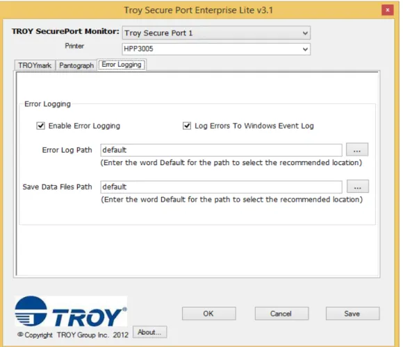
The Error Logging tab contains settings for enabling the error logging features of TSPE. The Enable Error Logging check box must be checked to enable any of the features.
The “Log Errors To Windows Event Log” check box should be checked if TSPE errors are to be logged to the Windows Event Log.
The Error Log Path is a valid path to a location where an error log file can be stored. A new log is created each day. Entering the word Default will cause TSPE to use the standard error logging location (Program Files\TROY Group\Port Monitor\PrintPort#\Error Log). Any value in this field will enable error logging to a file.
The Save Data Files Path is a valid path to a location where the print job files are stored. For a print job, two files are saved. One contains the original print stream coming from the data source application. It is named with a .prn extension. The second file contains the print stream after TSPE has inserted security commands. It is 50-06451-001 Rev A TROY Group Inc. Page 14 of 25
TROY Secure Print Enterprise Lite Users Guide
named with a .bak extension. These files provide the Troy technical support staff with the data needed to debug an issue. The word Default in this field will cause TSPE to store the data files in the standard location (Program Files\TROY Group\Port Monitor\PrintPort#\Backup).Figure 4.1: Error Logging tab.
TROY Secure Print Enterprise Lite Users Guide
Section 5
Printing the Pantograph
Introduction
The TROY Pantograph security feature consists of the copy protection background (pantograph), the micro-print border and the security features warning box. The pantograph can be micro-printed with all or some of these three components. Each component can be configured using the TROY SecurePort Monitor Configuration Utility.
Enabling the Pantograph
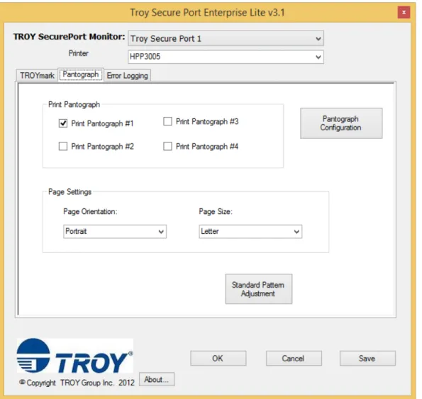
The Pantograph tab in the TSM Configuration Utility can be used to enable and configure the TROY Pantograph. Figure 5.1 below shows the Pantograph tab.
Figure 5.1: The Pantograph tab in the TSM Configuration Utility.
TROY Secure Print Enterprise Lite Users Guide
Up to four pantographs can be configured per Troy Secure Port. Each pantograph can be configured with different settings including the area of the page covered by the pantograph.In the Print Pantograph section, if a pantograph check box is checked, that pantograph will be printed. Checking any of the check boxes will enable the pantograph. If all four check boxes are unchecked, pantograph printing is disabled.
The Page Settings allow the user to select the page orientation and the page size of the page the pantograph will be printed on. The layout of the pantograph depends on the orientation and size of the page so that information is needed prior to printing.
Configuring the Pantograph
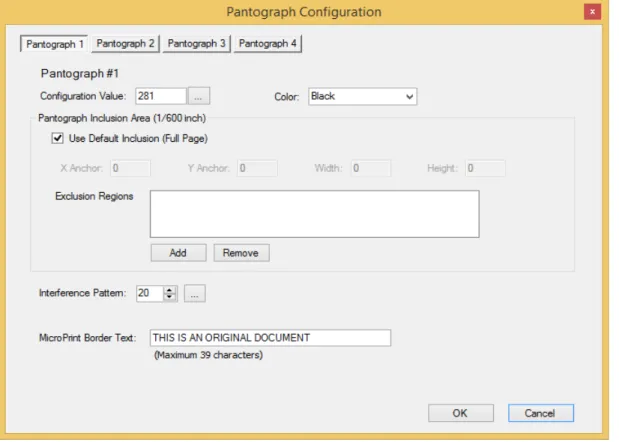
Selecting the Pantograph Configuration button on the Pantograph tab opens the Pantograph Configuration window.
Figure 5.2: Pantograph configuration screen.
Each of the four pantographs can be configured on this screen. The buttons at the top of the screen allow you to choose the pantograph to configure.
TROY Secure Print Enterprise Lite Users Guide
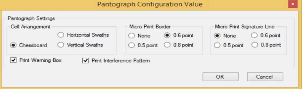
Configuration Value
The Configuration Value is a number used to define what components will be present in the pantograph. The button beside the Configuration Value text box opens a window that automatically calculates the value.
Figure 5.3: Pantograph Configuration Value screen.
The standard default pantograph consists of two cells appearing multiple times on a page. A pantograph cell is a rectangular area containing the pantograph message (Copy, Void, etc.). Cells are tiled across the page. The Cell Arrangement setting defines how the two cells are tiled.
- The Chessboard setting will create a pattern where the two cells will be alternated in a chessboard pattern across the page.
- The Horizontal Swathes setting creates a pattern where the cells will repeat horizontally across the page. First line will be cell 1, second line will be cell 2, third line will be cell 1, and so forth.
- The Vertical Swathes setting creates a pattern where the cells are repeated vertically. Setting the Cell Arrangement to Disabled prevents the cells from being printed.
The Micro Print Border and Signature Line can be set to 0.8, 0.6 or 0.5 font size. It can also be disabled. The Signature Line is a line of text printed in Micro Print font size that can be printed anywhere on the page. The location and length of the Signature Line cannot be configured in the TSM Configuration Utility. Those settings can be set in the XML configuration files (see Appendix A, Additional Pantograph Configuration). The Print Warning Box check box enables/disables the Warning Box.
The Print Interference Pattern check box enables/disables the Interference Pattern.
TROY Secure Print Enterprise Lite Users Guide
Pantograph Inclusion/Exclusion Region
The Inclusion Region defines the area of the page covered by the pantograph. The units are 1/600th of an inch. The X-Anchor and Y-Anchor defines the top left-hand corner of the pantograph.
An Exclusion Region is a rectangular area within the inclusion region where the pantograph is not printed. Multiple exclusion regions can be defined for each pantograph. The units are 1/600th of an inch and are relative to the inclusion region, not the page.
Note: The pantograph exclusion region will clear out all Troy security features in that area including the TROYmark™.
Additional Pantograph Settings
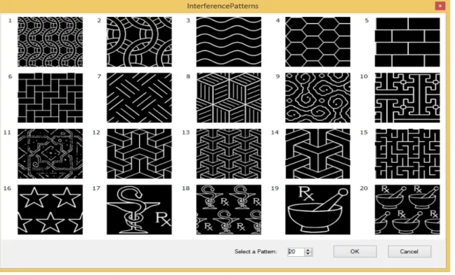
The Interference Pattern selector allows the user to select from 20 pre-configured interference patterns. Figure 5.5 below shows the 20 patterns. The 20 patterns can also be viewed from the configuration utility by selecting the … button beside the interference selector.
Figure 5.5: Interference Patterns ids.
The MicroPrint Border text box allows the user to set the text for MicroPrint Border. The maximum character limit is 39.
The Color drop-down list allows you to specify the color of the pantograph which includes UV (if ultra-violet toner is installed). The color affects all parts of the pantograph feature including the MicroPrint border and Warning Box.
TROY Secure Print Enterprise Lite Users Guide
Pantograph Pattern Adjustment
The pantograph consists of a foreground pattern of pixels and a background pattern of pixel. The characters that make up the copy text in a pantograph are printed using the foreground pattern. The background pattern is used to print background on the page.
The combination of the foreground and background patterns should create a condition where the characters are not visible on the printed page yet visible on a copy.
Different printer models produce variations in the patterns. Therefore, adjustments to the pantograph patterns are required for each model printer. The TSPE installation will provide a set of baseline pattern settings for the more common model printer. Other models not included in the installation will require pattern adjustments using the Standard Pattern Adjustment or the Pantograph Studio introduced in TSPE version 2.0.
The color pantograph was introduced in TSPE version 3.0. The color of the pantograph also creates variations in the patterns. Adjustment of the pattern is needed for each color.
Using the Baseline Patterns
The baseline patterns included in the installation can be selected from the Pantograph Pattern Quality Adjustment screen (see figure 5.6 below). The Load from Baseline Settings drop-down list contains a list of models included in the baseline list. Select the model from the list. The numbers in the Pattern Density Values will change to match the baseline values. Select Ok to use the new values.
Standard Pattern Adjustment
The first step in adjusting the pantograph pattern is to use the Standard Pattern Adjustment. To open the Pantograph Pattern Quality Adjustment window, select the Standard Pattern Adjustment button on the Pantograph tab.
In the window that appears, select the Pattern 1 check box then select Print Density Page button. Five pages will print on the default printer selected in the Printing tab. Make a copy of the five pages. Examine the printouts and the copies. Find a block where AB is least visible on the printout and visible on the copy. Enter this value in the Pattern 1 box in the Pattern Density Values section. If the patterns are too light, change the Darkness Factor value to 2 and print the 5 print the pages again.
Repeat this step for pattern 2. Typically pattern 1 and pattern 2 are the only patterns needed. If these patterns do not produce a good result, patterns 3 through 9 can be used.
TROY Secure Print Enterprise Lite Users Guide
Figure 5.6: Pantograph Pattern Quality Adjustment
TROY Secure Print Enterprise Lite Users Guide
Section 6
Printing the TROYmark™
Introduction
The TROYmark™ security feature is a background watermark printed as diagonally repeated pattern across the front or back of the page. The TROYmark™ can contain data from the document or configurable static text. Its purpose is to discourage fraudulent alteration of the document. Figure 6.1 below shows an example of the TROYmark™ on a check.
Figure 6.1: TROYmark™ example on a check.
Enabling TROYmark™
The TROYmark™ feature can be enabled from the TROYmark tab in the TSM Configuration Utility. Checking the Enable TROYmark™ check box, selecting a pattern and inclusion area enables the TROYmark™. Figure 6.2 below shows the TROYmark tab.
TROY Secure Print Enterprise Lite Users Guide
Figure 6.2: Default Settings tab in the TSM Configuration Utility.
Configuring the TROYmark™
The TROYmark™ configuration is set in the TROYmark tab of the TSM Configuration Utility application (see figure 6.2 above).
TROY Secure Print Enterprise Lite Users Guide
Inclusion Region
The Inclusion Region is the area of the page covered by the TROYmark™. The units are 1/600th of an inch. The X-Anchor and Y-Anchor defines the top left-hand corner of the pantograph.
Exclusion Region
The Exclusion Region is a rectangular area in the Inclusion Region when the TROYmark™ is not printed. Note: The TROYmark™ Exclusion Region will clear out all Troy security features in that area including the pantograph.
Line Spacing
The Line Spacing setting defines the space between each diagonal line in the TROYmark™. The units are 1/600th of an inch. The space is measured from the starting point of a line to the starting point on the next line in the horizontal and vertical directions.
Max Characters per Line
The Max Characters per Line setting is used to ensure all the data appears in the TROYmark™. The value is the maximum number of characters from the entire TROYmark™ string that will appear in a single line. Remaining characters will appear in subsequent TROYmark™ lines.
TROYmark™ on Back of Page
If the TROYmark™ is to be printed on the back of the page on a duplexing printer, the TROYmark™ on Back of Page check box should be checked. TSPE will insert the back page into the print stream.
Static Text
The TROYmark™ can contain static text configured in the ‘Static Text’ text box. Only alphanumeric characters can be used in the static text. Any other characters may trigger an error when saving the text o the XML configuration file.
TROY Secure Print Enterprise Lite Users Guide
Section 7
Adding New Secure Ports
Introduction
Some solutions may require printing to multiple printers from one machine or using multiple port monitor configurations for one printer. In both cases, multiple SecurePort Monitors are needed. The Add SecurePort Utility can be used to add additional TROY SecurePorts. Each TROY SecurePort consists of a TROYPORT port monitor and a print port folder containing configuration files for the port.
Add TROY SecurePort Utility
The Add TROY SecurePort Utility can be used to add new customized ports one at a time or multiple ports with default settings.
Figure 7.1: The Add TROY SecurePort screen.
To add a single secure port with customized settings, first enter a new in the New Port Name: text box or use the default name. Then select <Add new TROYPORT> from the TROYPORT Port Monitor drop down list. The Add TROYPORT window will appear. Adjust the settings or keep the default settings then select OK. Enter a Print Path and a Configuration Path. Using the word Default will cause the port to be created with the standard default path settings. Select OK or Save to save the settings.
To add multiple ports with the default settings, enter a number in the “Number Of Ports To Add” number box and then select the Add Multiple Ports button.
Use step 3 or Section 2 (Installation) above as a guide for creating a new print queue or queues connected to the new TROYPORT.