New Algorithm for the Smoothing Speed
Control of Induction Motor in Electric Car
based on Self-Tuning Parameter PID-Fuzzy
Logic
Dedid Cahya Happyanto
1, Soebagio
2, and Mauridhi Hery Purnomo
2AbstractDriving system of electric car for low speed has a performance of controller that is not easily set up on large span so it does not give a comfort to passengers.The study has been tested in the bumpy road conditions, by providing disturbances in the motor load, it is to describe the condition of the road. To improve the system performance, the speed and torque controller was applied using Field Oriented Control (FOC) method. In this method, On-Line Proportional Integral Derivative Fuzzy Logic Controller (PID-FLC) is used to give dynamic response to the change of speed and maximum torque on the electric car and this results the smooth movement on every change of car performance both in fast and slow movement when breaking action is taken. Optimization of membership functions in Fuzzy PID controller is required to obtain a new PID parameter values which is done in autotuning in any changes of the input or disturbance. PID parameter tuning in this case using the Ziegler-Nichols method based on frequency response. The mechanism is done by adjusting the PID parameters and the strengthening of the system output. The test results show that the controller Fuzzy Self-Tuning PID appropriate for Electric cars because they have a good response about 0.85% overshoot at to changes in speed and braking of electric cars.
Keywords Induction Motor, FOC, On-Line PID-FLC, Ziegler-Nichols
AbstrakSistem penggerak mobil listrik pada kecepatan rendah memiliki pengaturan kecepatan yang sulit di set pada jangkauan lebar sehingga tidak dapat memberikan kenyamanan pengendara. Penelitian ini juga diuji untuk kondisi jalan yang bergelombang, yaitu dengan memberikan gangguan pada beban motor penggerak untuk menggambarkan kondisi jalan tersebut.Untuk itu diperlukan kinerja sistem yang baik pada pengaturan Kecepatan dan Torka motor dengan metode Field Oriented Control (FOC). Dalam metode ini digunakan pengaturan Proporsional Integral Derivative Fuzzy Logic Controller (PID-FLC) secara On-Line untuk memberikan respon dinamis terhadap perubahan kecepatan dan torka pada mobil listrik, sehingga didapatkan kehalusan pada setiap perubahan kecepatan dan pengereman serta Torka maksimum motor. Optimasi fungsi keanggotaan pada kontroller PID Fuzzy diperlukan untuk mendapatkan nilai parameter PID yang baru secara autotuning setiap adanya perubahan nilai input atau gangguan, dalam hal ini menggunakan metode Ziegler-Nichols berbasis respon frekuensi, dengan mengatur parameter dan penguatan PID keluaran sistem. Hasil pengujian menunjukkan bahwa pengontrol Fuzzy PID Self-Tuning sesuai untuk diterapkan pada mobil Listrik karena mempunyai respon yang baik di sekitar 0,85% overshoot pada saat perubahan kecepatan dan pengereman mobil listrik.
Kata KunciMotor Induksi, FOC, PID-FLC secara On-Line, Ziegler-Nichols
I.INTRODUCTION1
he induction motor has more benefits because it is robust and relatively cheap. It is also mostly used in electric drive for the constant speed as propolsion electric car and no need regular maintenance [1]. However, it also has weakness in complicated speed control. The advance technology in electric drive makes this complication easy to solve. Electric car should be able to move smoothly such as ICE (Internal Combustion Engine) car started from the start having constant speed, the running with steady state condition and the breaking of which the car is driven slowly and stopped. Moving car in the way is needmotor speed controller.
Electric car was designed by a DC motor drive, and then develop it using a permanent magnet synchronous
1
Dedid Cahya Happyanto is with Electrical Engineering Polythecnic Institute of Surabaya, 60111, Indonesia, E-mail: [email protected].
Soebagio and Mauridhi Hery Purnomo are with Department of Electrical Engineering, Institut Teknologi Sepuluh November, Surabaya, 60111, Indonesia, E-mail: [email protected] and [email protected].
motor drive. In the next decade an electric car with a three-phase induction motor drive for an induction motor has many advantages, namely a smaller physique, robust and free maintenance [2]. System control was setted in the speed of an induction motor using an intelligent control. The mechanism was setting the control parameters based on determined of vector control [3].
motor using Fuzzy Logic Controllers (FLCs). In this case to control of speed an induction motor. FLCs combined with conventional PID controller to implement the decoupled system in induction motors [5]. The continuing with this research on fault tolerant control system to achiecve high performance induction motor drive as a drive on electric cars. In this study discussed how the vector control and FOC applied to an induction motor drive system on the electric car [6] combined with self-turning PID Fuzzy.
In the use of drive, electric car is often operated in high or low changing speed. And the operation of induction motor on low speed often gets in trouble. Therefore, the controller for managing the appropriate operation is needed to get high performance and quick response, control and characteristic paramount, and recovery speed as the result of dropped speed due to the car load effect. The role of the controller is to improve the response for managing proper speed.
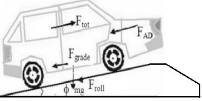
In the drive on electric cars need high performance and fast response dynamics, parameter control and speeds recovery characteristic caused by the speed drop due to impact the road condition, as shown in Figure 1. To improve the response speed is required in the regulation of a controller. Commonly used controllers are PID, but requires tuning PID reset when the load changes. Therefore, the fuzzy controller based on self tuning is implemented.
II.METHOD A. Electric Propulsion Design
Electric cars should be able to move a car matching the ICE starts from starting (acceleration), running (at steady state conditions), and breaking (deceleration and stops), therefore the motor speed to be controlled.
However, AC motors are nonlinear multivariable structure which coupled, thus setting the pace is more complicated, it is opposite to the DC motor which is a structure that decoupled by setting a more modest pace. Performance control of ac motors driving generally requires a complex control algorithm, implemented with a real time signal processing is fast. Evolution each discipline has contributed to the overall improvement in the technology of electric driving. Therefore, the development of power electronics technology and electric steering is very rapid, and advances in power electronics, microelectronics and microcomputer has allowed the use of supersophisticated control tasks can be realized. Because it must be a linear induction motor by operating through the method of Field Oriented Control (FOC).
Development of methods for the FOC is a method of operating the induction motor which has characteristics alike a DC motors, so that the flow field and flow perpendicular to the anchor. FOC method is a technique to improve vector control methods in the angle between the axis of the fictitious pole stator and rotor. Drive system is used to control the speed and braking of induction motors using a six step SVPWM inverter.
If the condition of the road is uneven, then the electric car should be made braking and motor speed must be reduced by changing the settings on the induction motor controller input. This should be done with changes in
parameter by self turning parameters system on the controller, as shown in Figure 2.
B. The Speed Controller
a. Field Oriented Control(FOC)
A motor works on the basis of induction process in the rotor part. When the current flows in the rotor coil, it creates induction that is caused by the differences between the rotor rotation and the field of stator, created by the static coils.
Electromagnetic torque (Te) is the function of stator
current and rotor current, such as: )
. .
(dr qs qr ds
e pM i i i i
T (1)
Notes :
M = coupled induction (H) ids = stator current on axes d (A) idr = rotor current on axes d (A) iqs = stator current on axes q (A) iqr = rotor current on axes q (A)
Rotor rotation speed is the function from electro-magnetic torque, and load torque such as:
l e r g
r K T T
dt d p
J
(2)
Notes :
Kg = constanta for fraction (kg.m2/s) J = moment of inersia (kg.m2) r = angular rotor speed (rad/s)
FOC method consists of controlling stator current in vector time phase transformation and speed in two coordinates d (torque component) and q (flux component). The basic diagram for FOC in three phases induction motor is, as on Figure 3.
Algorithm for the estimate motor flux such as:
m R m R r
ds i
dt di T
i
(3)
b m R r
qs r
b s
i T
i n dt d f
1
k k
k
k ds m R
r m R
nR
i
i
T
T
i
i
1
1 1
1
1
k K k
m R qs
b r k s
i i
T n f
T f
k k
k r b s
r1
1
Notes :
IFOC = Indirect FOC imR = magnetizing current fs = rotor flux speed
T = sampling time
n = rotor mechanical speed Tr = Lr /Rr (rotor time constant)
sλr = rotor flux position
ωb = electrical nominal flux speed
b. The development of PID fuzzy self tuning
PID Self Tuning Controller
are some methods offered which gives response to the Ziegler-Nichols steps such as a relay auto tuner or good tuning method. The good tuning is chosen because some resources mention that the Z-N method is the most common one, though, this method is sometimes not suitable to the plant being controlled. In order to get the three early paramount values of PID (Kp, Ti and Td), the
integral and its derivation are controlled and made them zero, and gradually the Kp value is increased so that it
reaches to the response level that is still in good tolerance. On a critical condition, Ultimate Gain (Ku)
and Ultimate Period (Tou) are gained in which Ku refers
to Kp value at that time and Tou value refers to the
distance between overshoot and under shoot peaks in the first time. To get the three paramount values of PID, Ku
and Tu values are inserted to the Table of Good Gain
Tuning method below, as on Table 1.
After the three early paramount values are gained, they are inserted to the general equation below:
t dt t de Td d e T t e Kc k u 0 ) ( ) ( 1 ) ( )( (4)
The problem which always appears to the conventional PID equation is when the good response set point is expected, the result is not good to the load changes. On the other hand, when good response to the load is expected, the result of setting point is a very high overshoot. Ideally, the good controller gives good response to the set point or changing load. And to overcome the existing weakness, according to reference [7], weighing factor β is added to the proportional side. According to the reference [8] if β is adjusted to the value that is less than one, the overshoot can be overcome and this adjustment does not influence the response caused by the changing load. The value β is modulated by the controller at the time and condition change. Therefore the PID equation above becomes:
) ( ) ( )) ( ( ) ( 1 k e T T i e T T k y yr Kc k u S d k i i s
(5)Notes :
yr = set point system,
y(k) = system output at (k) according to sensor reading.
According to reference [9], besides β, another paramount that influences the change of PID value is α. This paramount value contributes to the changes of integral and derivation domains, such as:
i d
ou i
u
pGG K T T T T
K , 0.25
1 3 , 8 . 0
(6)
When the α value on the above equation is 1, the Table of good gain tuning method is represented. Both PID and the above equations give us a conclusion that when the value α is 1 and the value β is also 1, the PID output return to the initial value. α and β values always change so that the PID paramount value changes according to certain condition on the sampling. And the changing of α and β values can be described as follows:
sf k h k sf k h k * ) ( ) ( * ) ( 1 ) ( (7) Notes:
hx (k) = fuzzy output at k for α changing, h(k) = fuzzy output at k for β changing,
sf = factor α scale, sf = factor β scale.
Fuzzy Logic Controller
Fuzzy logic is chosen to get various values for PID paramount. Fuzzy logic is a controller that represents the human thinking because it is based on linguistics. If an operator has operated a certain plant for long time, the intuition applied in the fuzzy logic rules can produce good control [10-11]. The following are the steps for logic controller:
1) Fuzzification
The first step in fuzzification is to transform the input range of variable values into the context of universal talk, and then the values are conversed into suitable linguistic values. In other words, the purpose of fuzzifier is to transform input room crisp U R into a fuzzy set that is defined as U, characterized as a function A :U [0.1] which is known in linguistic terms like ‘small’, ‘large’, and so on. There are some well-known fuzziliers but the most common is singleton fuzzilier, interpreting an input yo as a fuzzy set A into function A(y) that is equal to zero, except yo into function A(yo) equals to value 1.
2) Fuzzy Control Basic Rules
The basic rules of fuzzy control represent linguistic information and basic knowledge gained from technical experience. The following are control fuzzy rules expressed as conditional fuzzy statement {IF (antecedent) THEN (consequent)}. Antecedent is a fuzzy variable that represent a condition in applied domain and consequence is another fuzzy variable that is the control action. In general, these rules of fuzzy control are as the following: ,... 3 , 2 , 1 , is then is and , is x
:if A y B z C j
R j j j
j
(8) In which y is input variables for the fuzzy system, z is output variables, and Aj, Bj, Cj are fuzzy variables with their function membership that consecutively consists of Aj(x), Bj(y), and Cj(z). Each fuzzy control rule can be seen as description of relation among the fuzzy variables. This means that a fuzzy conditional statement can be implemented into fuzzy implication (fuzzy relation) as AjxBjCj which is then defined as fuzzy set in product space UxRj. Many implication fuzzy rules have been proposed lately, but the most common one is the minimum rule operation such as on Equation 9 below:
) ( ), ( ), ( min( ) , , ( ) , , ( z y x z y x z y x cj Bj Aj cj AjxBj Rj
(9)3) Fuzzy inference or concluding fuzzy is a mapping from fuzzy sets U into R, on the basis of fuzzy control rules and the conclusion from compositional rules. For example Ax is an any fuzzy set in U, then each value in
Rj determine a fuzzy set (AxoRj) within R based on
inference from the composition rule Equation 10 as follows: )] , , ( ), , ( min[ max )
(z m x y m x y z
mAxORj Ax Rj (10)
4) Defuzzyfication
Defuzzyfication includes the conversion of fuzzy control inference action into a crisp value then the crisp control is scaled into a suiTable range for the last control element. The most common method used is Center of Area (COA). In this method, the focus of membership function expansion is produced from the inference process being counted. When the space of talk is discrete, COA can be shown on the following equation:
n
i
i j n
i
i i j
z
1 1
) (
), (
(11)
which n is the amount of output quantity levels, and j(ωi) is degree of membership ωi , while ωi refers to the data at that time.
e(k) and Δe(k) become the fuzzy control inputs, and the fuzzy output is hx(k) for α side, and hβ(k) for β side. Fuzzy union on both input and output is made into seven memberships starting from Positive Big (PB) to Negative Big (NB). This is done in order to get output that is more precise.
The division of fuzzy membership is based on all possibilities that may happen in the system, both in the input and output. Figure 4 and 5 below are function of input and output fuzzy membership. Input error and delta error obtained from the rotary encoder sensor, the amount determined by the size of the desired motor speed. In this case the motor speed is set from 0 rpm to a top speed of 3000 rpm. Controller output signal is used to inject SVPWM inverter. Inverter input voltage ranging from 0 volts or 4 mA at the lowest speed up to 5 volts or 20 mA at the highest speed. In this case, to its limits membership function is started from 0 to 1.
After the input and output of membership function are obtained, the next step is to determine basic rules of fuzzy controller. This step is made as the interconnection between the input and output in any kind of condition. Tables 2 and 3 are basic rules that determine the output α and β consecutively. Fuzzy control rules (rule base) of a fuzzy logic controller, a set of control rules as the basis for state controller action. Rules were formulated based on observations or estimates of the dynamic response of the system. To determine the rule base used by the heuristic method of approach, by observing the response to the input, then the instinct of engineering (engineering science) is a fuzzy logic controller rule base accordingly [12].
After the input and output of membership function are obtained, the next step is to determine basic rules of fuzzy controller. This step is made as the interconnection between the input and output in any kind of condition. Tables II and III are basic rules that determine the output α and β consecutively.
Block diagram for fuzzy logic controller can be described as Figure 6. While the block diagram controller for fuzzy PID self tuning can be described in Figure 7.
III.RESULTS AND DISCUSSION
Research on Fuzzy PI self-tuning has been done by S.Vijayan, et al [13] and the results are shown in Figure
13. The research indicates that at high speed 1200 rpm the results are almost the same in good condition with self-tuning fuzzy PID. But at low speeds at 400 rpm, the results are less good when compared to the self-tuning fuzzy PID. However, electric cars in this research are operated at low speed.
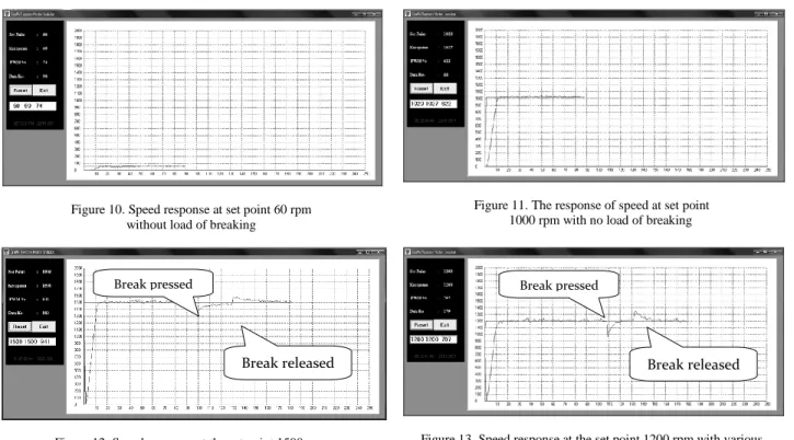
The examination process is done consecutively in order to find out the set point, which is then used to determine the early paramount PID value that becomes the set point to operate the plant. The process shows that the motor speed on the sensor becomes the feedback of the controller for making calculation and the act of controlling. Before executing all of this system, the controller is used to examine the motor speed data on some certain frequencies. This act is done by making addition from 1 to 255 register OCR2 to the controller Atmega 32 referred to reference. The act is executed because OCR2 is register 8 bit which has maximum value 255. If the value is 0, the output voltage used to drive the inverter is 0V. If the value is 255, the output voltage used to drive becomes 5V. This means that the motor is driven at high frequency. The three-phase inverter used is OMRON SYSDRIVE 3G3MV, that can be controlled from a local or remote area. The inverter can be controlled from outside by adjusting the mode. And when the inverter is controlled from a remote area it needs to be fed with 0mA-20mA or 4mA-20mA current. It can also be controlled from a remote by the voltage 0V-5V. To ease the remote control, the inverter can be controlled through its input voltage because its output voltage from microcontroller is 5V. When this output is modulated via PWM, the output voltage will vary from 0V to 5V. Experimental module of on-line speed and braking control of induction motors is shown in Figure 8. Figures 10 to 12 show the data of examination of a tool. Figure10 is taken when the set point is controlled at speed 60 rpm. The response on this speed has shown the good speed because there is no speed oscillation which gives comfort to the passengers of electric car driven in the city in the rush hour. In general the control of induction motor in the low speed has a problem caused by the existing resistance R that cannot be avoided at speed ω; though, it is small due to the impedance of motor (R+jω). When the motor speed is increased at high speed, the response of speed is also good as it does not make oscillation. The response of speed is shown in Figure 11.
When the motor is driven at speed 1500 rpm, higher than 60 rpm, or when the break is promptly pressed or released, or when the overshoot is not so high that the motor is in steady state, the response still shows good speed. This means that the controller runs well such as shown on Figure 12. The good response also happens when the high speed is 1200 rpm, or when the break is pressed, or when the pressing break is released such as shown in Figure 13.
when it is applied for the maximum frequency, reaches the speed 1770 rpm.
IV.CONCLUSION
Having done both the examination process and comparison of related theories, some findings can be presented as follows:
Self-tuning PID fuzzy control method is good enough to use on a variety of changes in set point because it has a good adaptability.
In high frequency operation, the control method can produce better percent overshoot.
Steady state error is relatively very small on the examination of some set points.
Figure 1. The running of electric car on the road [5] Figure 2. Configuration electric drive propulsion
Figure 3. Control diagram for induction motor speed Figure 4. Membership function on the second fuzzy input
Figure 5. Membership function for the second fuzzy output Figure 6. Block diagram for fuzzy logic controller
0 0.2 0.4 0.6 0.8 1 1.2
-3000 -2250 -1500 -750 0 750 1500 2250 3000
D
e
gree
of
Mem
be
rs
hip
Membership Function E and DE
NB NM NS Z PS PM PB
0 0.2 0.4 0.6 0.8 1 1.2
-1 -0.75 -0.5 -0.25 0 0.25 0.5 0.75 1
De
gr
e
e
o
f M
e
m
b
e
rs
h
ip
Membership Function H1 and H2
NB NM NS Z PS PM PB
Battery Inverter 3-Phases Induction
Motor Computer Input
setting
Self Turning Controller
Trans mision
β α
hβ
hα
e(k) Δe(k)
Fuzzy control Rules
Inference Engine sfde
sfe
Figure 7. Block diagram of fuzzy PID self tuning
(a) (b)
(c)
Figure 8. Experimental results of PI-Fuzzy speed control [13]
Figure 9. Experimental module of on-line speed and braking control of induction motors β
α
e e
Process PID
Fuzzy Adaptation
Figure 10. Speed response at set point 60 rpm without load of breaking
Figure 11. The response of speed at set point 1000 rpm with no load of breaking
Figure 12. Speed response at the set point 1500 rpm with various presser in breaking load
Figure 13. Speed response at the set point 1200 rpm with various presser in breaking load
TABLE 1 GOOD GAIN TUNING METHOD
Controller Type KpGG Ti Td
PID 0.8Kp 1.5Tu 0.25Ti
TABLE 2
FUZZY BASIC RULES TO DETERMINE VALUE H1 H1 NB NM NS Z PS PM PB NB NB NB NM PB PM PS Z NM NB NM NS PM PS Z NS NS NB NM NS PS Z NS NM Z NB NM NS Z NS NM NB PS NM NS Z PS NS NM NB PM NS Z PS PM NS NM NB PB Z PS PM PB NM NB NB
TABLE 3
FUZZY BASIC RULES TO DETERMINE VALUE H2 H2 NB NM NS Z PS PM PB NB NB NB NM PB PM PS Z NM NB NM NS PM PS Z NS NS NB NM NS PS Z NS NM Z NB NM NS Z NS NM NB PS NM NS Z PS NS NM NB PM NS Z PS PM NS NM NB PB Z PS PM PB NM NB NB
REFERENCES
[1] Emadi, Y. J. Lee, and K. Rajashekara, Power Electronics and Motor Drives in Electric, Hybrid Electric, and Plug-In Hybrid Electric Vehicles, IEEE Transactions On Industrial Electronics, vol. 55, no. 6, June 2008.
[2] M. Zeraoulia, M. E. H. Benbouzid, and D. Diallo, Electric Motor Drive Selection Issues for HEV Propulsion Systems: A Comparative Study, IEEE Transactions on Vehicular
Technology, vol. 55, no. 6, November 2006.
[3] J.-S. Yu and S.H. Kim, Fuzzy logic based Vector Control scheme for permanent magnet Synchronous motors in elevator drive applicantion, IEEE Trans on Industrial Electronics, vol 54, no. 4, August 2007.
[4] A. M. Bazzi, Designing Better Induction Motor Drive Systems,
From Efficiency, Reliability, And Power Electronics
Perspectives, University of Illinois at Urbana-Champaign, 2010,
pp. 66.
[5] B. Robyns, F. Berthereau, J.-P. Hautier, and H. Buyse, Multimodel field orientation in an indirect field oriented control (FOC). IEEE Transactions on Industrial Electronics, vol. 4, no. 2, April 2000.
[6] D. Diallo and M. E. H. Benbouzid, Fault Tolerant Control System High Performance Induction Motor Drive for the Electric Vehicle, IEEE Transaction On Vehicular Technology, vol. 5, no.6, November 2004.
[7] B. Tabbache, A. Kheloui, and M.E.H. Benbouzid, Design and Control of the Induction Motor Propulsion of an Electric Vehicle, IEEE VPPC, 2010.
[8] Z. Lubis, A. N. Abdalla, and Mortaza, Mathematical Modeling of the Three Phase Induction Motor Couple to DC, American J.
of Engineering and Applied Sciences, pp. 715-719, 2009.
[9] M. E. H. Benbouzid, D. Diallo, and M. Zeraoulia, “Advanced fault-tolerant control of induction motor drives for EV/HEV traction applications: From conventional to modern and intelligent control techniques,” IEEE Trans. Vehicular
Technology, vol. 56, pp. 519-528, March 2007.
[10] M. Khan and N.C. Kar, Performance Analysis of Fuzzy Based Indirect Field Oriented Control of Induction Motor Drives for Hybrid Electric Vehicles, presented at PHEV2007 Conference, Canada, November 1&2, 2007
[11] A. Nasri and A. Hazzab, Fuzzy-Sliding Mode Speed Control for Two Wheels Electric Vehicle Drive, Journal of Electrical Engineering & Technology, vol. 4, no. 4, pp. 499-509, 2009. [12] L-X, Wang. A Course in Fuzzy Systems and Control, Upper
Saddle River, NJ: Prentice-Hall, Inc., 1997.
[13] S. Vijayan, S. Paramasivam, and R. Arumugam, An Intelligent Self-Tuning PI Type Fuzzy Logic Controller for a Switched Reluctance Motor Drive, Iranian Journal of Electrical and
Computer Engineering, vol. 6, no. 2, Summer-Fall 2007.
Break pressed
Break released
Break pressed
![Figure 8. Experimental results of PI-Fuzzy speed control [13]](https://thumb-us.123doks.com/thumbv2/123dok_us/8133183.2157032/6.893.76.789.327.650/figure-experimental-results-pi-fuzzy-speed-control.webp)