Implementation of Real Time Alert System over Cloud Computing
Jaeseok Shim and Yujin Lim
1University of Suwon
{sjs0915, yujin}@suwon.ac.kr
Abstract
In recent years, cloud computing is becoming popular that can provide an open, flexible, and reconfigurable platform for several monitoring and controlling applications. In this paper, we implement a real time alert system on top of a cloud computing platform. Our system recognizes a variety of events that occur in the monitored space and notifies them a control center in real time. Through implementation of the system, we show the functionality and feasibility of our system.
Keywords: Cloud computing, Wireless sensor network, Real time alert
1. Introduction
Wireless Sensor Network (WSN) is a network of sensors deployed in a physical world that interacts with the environment. It has been gaining increasing attention, both from the academia and industry, because of its potential to be a practical solution across multiple areas such as asset management, target monitoring, security and surveillance [1, 2], and industrial automation. Typically, WSN is controlled by its own applications that can access sensors within the network. On the other hand, sensors are not easily accessed by applications outside of the network. Even within the same network, different applications may encounter a race condition when they are trying to access a sensor simultaneously [3].
In the past few years, cloud computing [4] has emerged as a new computing paradigm to provide reliable resources, software, and data on demand. As for resources, cloud computing services provide users with virtual servers. Users utilize virtual servers without concerning about their locations and specifications. Besides, users can use and control sensors through virtual servers, irrespective of their applications.
In this paper, we use a cloud service for deploying a real time alert system. The system is required to recognize a variety of events that occur in the monitored space and notify them a control center in real time. Thus, it provides a control center with an opportunity to evaluate the situation and take preventive action if necessary. Sensors deployed in the monitored space send their sensor data to the cloud through cloud gateways. The cloud gateway extracts meaningful data from raw sensor data and processes the extracted data for specific tasks on a real time alert system. Then, the cloud gateway forwards and stores the processed data in cloud storage servers. The stored data is analyzed and, if abnormal object like an intruder is detected, the analyzed data is sent to a control center for notifying of the abnormal event.
We implement a real time alert system on top of a cloud computing platform. First, we design a real time alert system and define the architecture of a cloud gateway. Then, we implement the system and the gateway. To show the feasibility and functionality of our system, we carry out experimental tests in our real campus.
1
The remaining paper is organized as follows. We introduce the related works in Section 2. In Section 3, we design our real time alert system and define the architecture of a cloud gateway. In Section 4, we implement our system in our campus and show the performance of the system. Finally, the conclusion remarks are given in Section 5.
2. Related Work
Cloud computing can be used that physical sensors accumulate their data and transmit all sensor data into cloud storage servers for processing and analyzing. It handles sensor data efficiently for monitoring applications. It collects and processes information from several WSNs to enable information sharing on big-scale and to collaborate the applications on the cloud among users. It enables users to easily gather, access, process, visualize, analyze, store, share, and search large number of sensor data from several types of applications by using the computational resources and storage resources of the cloud [5].
There have been a few of studies on the management of physical sensors [6]. OGC (Open Geospatial Consortium) [7] defines Sensor Modeling Language (SensorML) [8] to provide standard models and an XML encoding for physical sensors’ description and measurement processes. SensorML represents the metadata for any physical sensor, such as the type of physical sensor, the location, and the accuracy. Although there are many kinds of physical sensors, no application uses all of them. Each application needs specific types of physical sensors for its requirements. A publish/subscribe mechanism [9] is used to select physical sensors. When there are multiple WSNs, each WSN publishes sensor data and metadata that describes the type of physical sensors. Each application subscribes to one or more WSNs to receive a real-time data from specific types of physical sensors. Such publish/subscribe mechanism allows each application to selects only the types of physical sensors it needs. In addition, through the cloud service, users check whether the physical sensors are available and detect physical sensors’ faults for keeping the quality of the data coming from physical sensors. FIND [10] provides a method to detect physical sensors with data faults. FIND ranks physical sensors based on their sensor data as well as their physical distances from an event. FIND considers a physical sensors’ fault if there is a significant mismatch between the sensor data rank and the distance rank.
Previous studies have focused on the control of various physical sensors. In this paper, we focus how to practically implement a real time alert system. For this goal, we design the architecture of the system and implement the system on top of a cloud platform. Then, we carry out experimental tests to analyze the performance of the system.
3. A Real Time Alert System
We design a real time alert system on top of a cloud platform, as shown in Figure 1. The system is divided into three parts. In the first part, many sensors are deployed in the monitored space. The monitored space can be buildings, floors, or rooms. In our system, our college building in campus is the monitored space. The space is divided into 5 floors and, in each floor, there are many lecture rooms and laboratories. Considering the interior structure of our building, we deploy a number of WSNs. For each WSN, one or more sensor gateways are connected, and they collect the sensor data from sensors and forward the data to the cloud gateway. The cloud gateway receives the sensor data from sensor gateways and extracts meaningful data by applying semantic filters in order to remove meaningless data and reduce the volume of data. In our system, a semantic filter does not mean that it filters the sensor data from inaccurate, incomplete, or noisy data. It extracts the meaningful data according to
specific tasks on the system. For example, the height of an intruder (i.e., human) in a building is generally between 150cm and 200cm. The height of a target object is computed by using the sensor data. Then, if the height of the object is within a reasonable range, the corresponding sensor data is extracted. The extracted data is the meaningful data to the specific task for detecting of an intruder. Thus, in order to reduce the volume of data and efficiently manage cloud storages, we store the only meaningful data on cloud storages, as the second part of our system. Then, to transform the stored data into services-based structure, a control center, as the third part of our system, pulls the stored data on servers for a specific task to be processed. The processed data is accessed for situation analysis and also the environmental data is fetched for visualization.
Figure 1. Architecture of a real time alert system
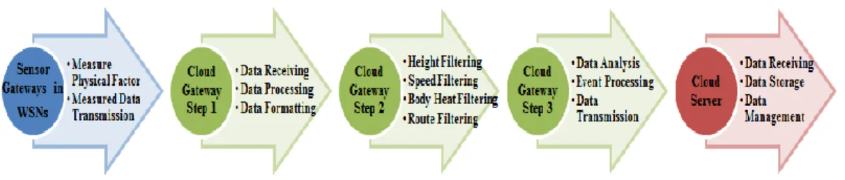
In the designed system, we define the architecture of a cloud gateway . A cloud gateway connects the scattered WSNs and the cloud [11]. To provide efficient cloud gateway for our system, several functions need as shown in Figure 2. We divide the operating process of the cloud gateway into three steps. In the first step, when the cloud gateway receives the data, it processes heterogeneous sensor data, many of which may have their own distinct features for security and surveillance service. Then, it encodes the data in a standard data format like XML. In the second step, the gateway applies semantic filters to extract a meaningful data. In our system, a meaningful data indicates the sensor data to be measured when the detected object is a human, i.e., intruder. Our filters are composed of height filter, speed filter, body heat filter, and route filter. The height filter checks whether the height of a target object is within a reasonable range, e.g., between 150cm and 200cm. The speed filter checks whether the mobility speed of the target is within a reasonable range, e.g., between 0.5m/sec and 2.5m/sec [12]. The body heat filter checks whether the body heat of the target is between 9.4um and 10.4um when IRS (Infrared Ray Sensor) is used. Finally, the route filter checks whether the target moves according to the building structure. In the last step, the gateway analyzes the extracted data to identify the status of detected event, such as no target is detected, target is detected, or the detected target is an intruder. The identified event is processed to convert into a cloud service specific data format if necessary. Then, the converted data is transmitted to the cloud storage servers. If the identified event needs an emergency action, the gateway notifies the event of a control center. The control center analyzes the event based on the data stored on the storage servers, and takes action if necessary.
Figure 2. Architecture of our cloud gateway
3.1. Height filter
In this paper, we focus on the height filter among various semantic filters in our cloud gateway. In order to estimate the height of a target object, we employ Heron’s formula to calculate the area of a triangle, like a triangle with three sensor A, B, and C in Figure 3. We assume that sensors are deployed on a ceiling in the monitored space. The area of a triangle with three points A, B, and C (i.e., ) is calculated by Heron’s formula as below.
√ . (1) We assume that the height of the target is reasonable when the distance (i.e., w) from a ceiling to the target is between h and h+∆. It indicates that the target is an intruder. When the target object is located at and the distance between a ceiling and is zero, is the sum of , , and as below.
√
√ √
√ (2) When the target is located at and the distance between a ceiling and is , is calculated by using , , and , instead of , , and , as below.
√
√ √
√ (3) where , , and compensate for the increased area due to distance . When the distance is zero, (3) is the same with (2). When the target is located at and the
distance between a ceiling and is , is calculated by using , , and , instead of , , and , as below.
√ (4)
√ √ √
where , , and compensate for the increased area due to distance . When the distance is zero, (4) is the same with (2). Thus, by using the relationship in (3) and (4), we can estimate the height of a target object and determine whether the target is a human.
Figure 3. Concept of our height filter
4. Implementation of a Real Time Alert System
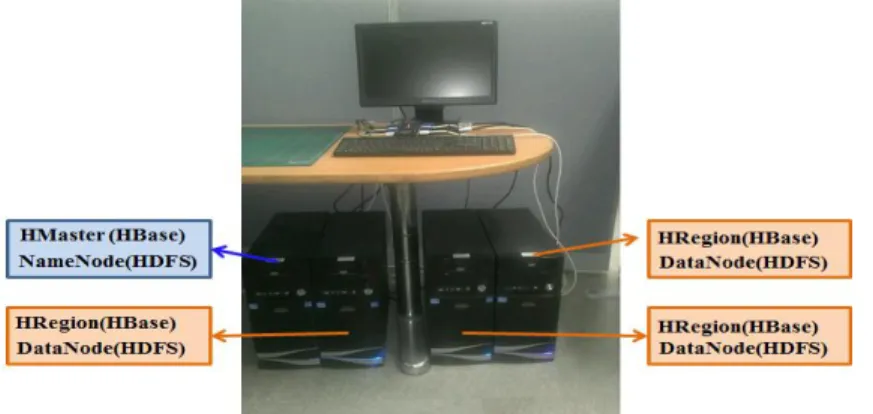
In order to show functionality and feasibility of our system, we have implemented a real time alert system. We have employed cloud-serving systems, such as Hadoop [13] and HBase [14]. Hadoop Distributed File System (HDFS) acts as the primary storage of Hadoop. HBase is a distributed column-oriented database built on top of HDFS based on the common computer cluster. In this paper, the system is implemented on Hbase 0.94.2 and Hadoop 2.0.0 using Java 1.6.0 with ssh to remotely manage Hadoop daemon. We configure our system on 4 PCs, as shown in Figure 4. All sensors are implemented on the mote modules [15] equipped with DMS (Distance Measuring Sensor) and PIR (Passive Infra-Red). The communication between sensors is based on IEEE 802.15.4 standard. We deploy four sensors on a ceiling in each room of our college building.
Figure 4. Implemented system in a distributed environment
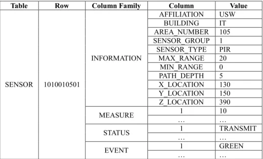
On top of the cloud platform, we design database schema to store sensor data which is sent from our cloud gateway, as shown in Figure 5. For each sensor, sensor ID is assigned. Sensor ID is composed of affiliation ID, building ID, room ID which the corresponding sensor
belongs, and sequence number. In the figure, 1010010501 is the sensor ID. In the ID, the first two digits refer affiliation ID, the next two digits refer building ID, the next four digits are room ID, and the last two digits are the sequence number. In HBase, columns are grouped into column families. Our schema has four column families: INFORMATION, MEASURE, STATUS, and EVENT. INFORMATION column family is mainly composed of a type of the sensor, the geographic coordinates of the sensor, and measurement range. We have used two types of sensors such as DMS and PIR. In MEASURE column family, five measured sensor data are recorded at each time period. STATUS column family indicates the operating state of the sensor, i.e., SLEEP, IDLE, RECEIVE, or TRANSMIT. EVENT column family indicates the monitoring status, i.e., target is not detected (the value of the column is “GREEN”) or target is detected (the value of the column is “RED”). The stored data on HBase can be accessed for situation analysis by a control center.
In order to process the data for situation analysis, a control center uses our web interface implemented using Java. The control center pulls the data to be stored according to the designed schema on servers, through the web interface as shown in Figure 6 and 7. Thus, the control center manages and views the current running state of our real time alert system. In Figure 6, buttons in the left side indicates the monitored space within our college building, such as room IT105, IT205, IT309, and IT502. When one of buttons is selected, “SENSOR” window shows a list of sensors to be deployed in the selected room. In the figure, the window shows the list of sensors deployed in room IT105. “STATUS” window graphically shows the status of each sensor, such as SLEEP, IDLE, RECEIVE, or TRANSMIT. When we select a specific sensor, e.g., “105-1” in Figure 6, we can see Figure 7. It shows the coordinates of the sensor and the type of sensor. In the upper window of the figure, the measured data are recorded at each time period. At each time period, the sensor measures five times, such as Sample1, Sample2, Sample3, Sample4, and Sample5. The lower window of the figure indicates the status of the sensor.
Table Row Column Family Column Value
SENSOR 1010010501
INFORMATION
AFFILIATION USW
BUILDING IT
AREA_NUMBER 105
SENSOR_GROUP 1
SENSOR_TYPE PIR
MAX_RANGE 20
MIN_RANGE 0
PATH_DEPTH 5
X_LOCATION 130
Y_LOCATION 150
Z_LOCATION 390
MEASURE … 1 10 …
STATUS … 1 TRANSMIT …
EVENT … 1 GREEN …
Figure 6. The web interface to access the sensors’ information
Figure 7. The web interface to access the measured data
5. Conclusion
In this paper, we have designed and implemented a real time alert system on top of the cloud infrastructure. First, we design the architecture of the system. In the designed system, in order to efficiently gather the sensor data from WSNs and store the data on cloud storage servers, we group the functionalities of the cloud gateway and define the architecture of the gateway. Then, we implement the cloud gateway and real time alert system on top of Hadoop cloud-serving platform. Through the implementation, we show the functionality and feasibility of our system.
Acknowledgements
This research was supported by Basic Science Research Program through the National Research Foundation of Korea (NRF) funded by the Ministry of Education, Science and Technology (2012-0007877)
References
[1] G. Simon, M. Maróti, A. Lédeczi, G. Balogh, A. Nádas, G. Pap, J. Sallai and K. Frampton, “Sensor Network-based Countersniper System”, Proceedings of the ACM 2nd International Conference on Embedded Networked Sensor Systems, (2004) November 3-5; Baltimore, USA.
[2] S. K. Dash, J. P. Sahoo, S. Mohapatra and S. P. Pati, “Sensor-Cloud: Assimilation of Wireless Sensor Network and the Cloud”, Springer Lecture Notes of the Institute for Computer Sciences, Social Informatics and Telecommunications Engineering, vol. 84, (2012), pp. 455-464.
[3] Y. -C. Chou, B. -S. Huang and B. -J. Peng, “Embedded Systems - High Performance Systems”, Applications and Projects, Edited by InTech, New York, Chapter 5, (2012), pp. 87-102.
[4] A. Weiss, “Computing in the Clouds”, ACM netWorker - Cloud computing: PC functions move onto the web, vol. 11, no. 4, (2007), pp. 16-25.
[5] A. Alamri, W. S. Ansari, M. M. Hassan, M. S. Hossain, A. Alelaiwi and M. A. Hossain, “A Survey on Sensor-Cloud: Architecture, Applications, and Approaches”, Hindawi International Journal of Distributed Sensor Networks, vol. 2013, (2013), pp. 1-18.
[6] M. Yuriyama and T. Kushida, “Sensor-Cloud Infrastructure Physical Sensor Management with Virtualized Sensors on Cloud Computing”, Proceedings of the IEEE 13th International Conference on Network-Based Information Systems, (2010) September 14-16; Takayama, Japan.
[7] Open Geospatial Consortium, http://www.opengeospatial.org. [8] SensorML, http://vast.uah.edu/SensorML/.
[9] J. Shneidman, P. Pietzuch, J. Ledlie, M. Roussopoulos, M. Seltzer and M. Welsh, “Hourglass: An Infrastructure for Connecting Sensor Networks and Applications”, Harvard Technical Report TR-21-04,
(2004).
[10] S. Guo, Z. Zhong and T. He, “FIND: Faulty Node Detection for Wireless Sensor Networks”, Proceedings of 7th ACM Conference on Embedded Networked Sensor Systems, (2009) November 4-6; Berkeley, USA. [11] Z. Wei, J. Li, Y. Yang and D. Jia, “A Residential Gateway Architecture based on Cloud Computing”,
Proceedings of IEEE International Conference on Software Engineering and Service Sciences, (2010) July 16-18; Beijing, China.
[12] T. Suzuki, A. Khan, M. Kobayashi and W. Takita, “Collaboration in Routing and Velocity Measurement Function or Mobile Ad Hoc Networks”, Proceedings of IEEE International Conference on Future Generation Communication and Networking, (2007) December 6-8; Jeju, Korea.
[13] Apache Hadoop, http://hadoop.apache.org. [14] Apache HBase, http://hbase.apache.org.
[15] C. Suh, J. -E. Joung and T. -B. Ko, “New RF Models of the TinyOS Simulator for IEEE 802.15.4 Standard”, Proceedings of IEEE International Conference on Future Generation Communication and Networking, (2007) March 11-15; Kowloon, Hong Kong.