Adaptive Paddle Board: Final Design Review
P
REPARED FORT
HEC
ENTRALC
ALIFORNIAA
DAPTIVES
PORTSC
ENTERPresented by:
The Adaptive Paddle Team
Sean Yueh
Alexander Holthaus
Garrett Holmes
Garett Jones
M
ECHANICAL
E
NGINEERING
D
EPARTMENT
C
ALIFORNIA
P
OLYTECHNIC
S
TATE
U
NIVERSITY
Statement of Disclaimer
Abstract
i
Contents
Statement of Disclaimer ...2
Contents ... i
List of Figures ... iv
List of Tables ... vi
1 Introduction ...1
2 Background ...1
2.1 Customer Needs ... 1
2.2 Existing Designs ... 2
2.3 Patent Search ... 4
2.3.1 Paddleboard with Removable Seat (US8752492B1) ... 4
2.3.2 Vertical Bicycle Storage Rack (US20130270201A1) ... 4
2.3.3 Longitudinally Adjustable Mount for a Snowboard Binding (US20010038182A1) ... 5
2.3.4 Binding Mounting System for Recreational Board (US20050248129A1) ... 5
2.3.5 Adjustable Scope Mounting System (US7543405B1) ... 6
2.4 Technical Literature ... 6
2.4.1 Wheelchair Manufacturers’ Reporting ... 7
2.4.2 Wheelchair Buyer’s Guide ... 7
2.4.3 Medical Case Study ... 7
2.4.4 Previous Senior Projects ... 7
2.4.5 Surfboard Foam Discussion ... 8
2.5 Disability Regulations ... 8
3 Objectives ...9
3.1 Formal Problem Statement ... 9
3.2 Boundary Diagram ... 9
3.3 Scope ... 10
4 Concept Design Development ... 12
4.1 Ideation Generation and Development Process ... 12
4.1.1 Attachment Frame ... 12
4.1.2 Anchor Straps ... 13
4.1.3 Stabilizing Outriggers ... 14
ii
4.2 Design Selection Process ... 14
4.3 Selected Concept Design ... 15
4.3.1 Attachment Frame ... 16
4.3.2 Anchor Straps ... 17
4.3.3 Stabilizing Outriggers ... 17
4.3.4 Loading Ramp ... 18
4.4 Preliminary Analyses ... 19
4.5 Risks and Challenges ... 20
5 Final Design ... 21
5.1 Final Design: Subsystems and Components ... 21
5.1.1 Attachment Frame ... 22
5.1.2 Anchor Straps ... 24
5.1.3 Stabilizing Outriggers ... 26
5.1.4 Loading Ramp ... 27
5.2 Safety, Maintenance, and Repair Considerations ... 28
5.3 Cost Analysis ... 29
6 Manufacturing Plan ... 29
6.1 Aluminum Frame System ... 30
6.2 Loading Ramp System ... 31
6.3 Stabilizing Outrigger System ... 32
6.3.1 CNC Machining ... 32
6.3.2 Adhesion ... 33
6.3.3 Model Shaping ... 33
6.3.4 Fiber Glass Reinforcing ... 34
6.3.5 Strut Insert Installation ... 37
6.3.6 Gel Coating ... 38
6.4 Wheelchair Tie-down Strap System ... 39
6.4.1 Frame Attachment Strap ... 39
6.4.2 Buckle Attachment Strap ... 39
6.5 Strap System Assembly ... 40
7 Design Verification Plan ... 40
7.1 Pre-Build Tests ... 40
iii
7.1.2 Hydrodynamic Drag Test ... 41
7.2 Mid-Build Tests ... 41
7.2.1 Balance ... 41
7.3 Post-Build Tests ... 41
7.3.1 Setup and Teardown ... 41
7.3.2 Tipabiliby ... 41
7.3.3 Loaded Paddle Test ... 42
8 Project Management ... 42
8.1 Gantt Chart... 42
8.2 Redesign ... 42
8.3 Challenges ... 42
9 Conclusion & Recommendations ... 43
9.1 Achievements ... 43
9.2 Next Steps for Sponsor ... 45
10 References ... 46
Appendix A: QFD House of Quality ... 47
Appendix B: Pugh Matrices and Weighted Decision Matrices ... 48
Appendix C: Preliminary Analysis ... 55
Appendix D: Design Hazard Checklist, Risk Assessment, & FMEA ... 56
Appendix E: BOM & Assembly Drawings ... 60
Appendix F: Project Budget ... 84
Appendix G: Test Results ... 87
Appendix I: Operator’s Manual... 95
Appendix J: Design Verification Plan & Report ... 106
Appendix K: HDPE Ramp Calculation ... 107
iv
List of Figures
Figure 2.1 Onit Paddle Boards ... 2
Figure 2.2 Expandacraft Outrigger Kit ... 3
Figure 2.3 Removable Seat Paddle Board Drawing... 4
Figure 2.4 Vertical Bicycle Rack Sketch ... 5
Figure 2.5 Longitudinally adjustable snowboard binding mounting system exploded view ... 5
Figure 2.6 Cross section of a binding mounting system installed into a recreational board ... 6
Figure 2.7 Dovetail rail mounting system for scopes on rifles ... 6
Figure 2.8 Detailed Material Composition of the TekEfx Paddle Board ... 8
Figure 2.9 Typical Wheelchair Dimensions for Large Male, ADA Title III ... 8
Figure 3.1 Boundary Diagram Sketch ... 9
Figure 3.2 Telescoping outrigger diagram ... 11
Figure 4.1 Frame with harness Figure 4.2 Side cups with harness ... 13
Figure 4.3 Velcro strap Figure 4.4 Four-point strap attachment ... 13
Figure 4.5 Outrigger ... 14
Figure 4.6 Siderigger pontoon ... 14
Figure 4.7 Peg and arm ramp ... 14
Figure 4.8 Complete Paddleboard Assembly ... 16
Figure 4.9 Anchor Base Subsystem ... 16
Figure 4.10 Strap Connection Configuration ... 17
Figure 4.11 Outrigger Subsystem ... 18
Figure 4.12 Loading Mechanism Subsystem ... 19
Figure 4.13 Transverse beam critical failure location (in orange) ... 20
Figure 5.1 Exploded view of overall design assembly ... 22
Figure 5.2 Exploded model of frame subsystem... 23
Figure 5.3 Exploded view of frame and paddleboard ... 24
Figure 5.4 Bolted strap attachment to frame ... 24
Figure 5.5 Velcro strap attachment to chair ... 25
Figure 5.6 CAD model of outrigger pontoon... 26
Figure 5.7 CAD Model of Ramp ... 27
Figure 6.1 Manufacturing system flowchart ... 30
Figure 6.2 Box Beam Welded to Longitudinal Rail ... 31
Figure 6.3 ShopBot prior to cutting a sheet of foam ... 33
Figure 6.4 Sanding interior radii with a disk sander ... 34
Figure 6.5 Pontoon Fiber Glassing Flowchart ... 34
Figure 6.6 Mock lay-up of an external layer of the bottom ... 35
Figure 6.7 Exterior layer wet lay-up with excess hanging down... 35
Figure 6.8 Removing Excess material with the reciprocating saw and disk sander ... 36
Figure 6.9 Mock lay-up of the second interior layer ... 36
Figure 6.10 Un-glassed top layer glued on the bottom section... 37
Figure 6.11 Carbon fiber reinforcement pattern ... 38
Figure 6.12 Fiberglass reinforcement patterns ... 38
v
Figure 6.14 Components of the strap attachment system ... 40
Figure 9.1 Completed Project at Senior Project Exposition ... 44
Figure 0.1. Team members attempting to capsize system ... 89
Figure 0.2. Strap and bolt test assembly ... 90
Figure 0.3. Strap tearing after testing ... 91
vi
List of Tables
Table 2.1 Customer Requirements and Specifications ... 2
Table 2.2. Onit Ability Board Specifications ... 2
Table 3.1. Engineering Specification Table ... 10
Table 4.1. Morphological Table ... 15
Table 5.1 Materials cost summary ... 29
Table 6.1 Aluminum Frame Components ... 30
Table 6.2 Purchased Ramp Materials ... 31
Page | 1
1
Introduction
Our team of four mechanical engineering seniors, sponsored by Randy Coffman of the Central California Adaptive Sports Center, aims to develop an affordable adaptive paddle board for persons with mobility-affecting disabilities to overcome such obstacles. Mr. Coffman works with Adaptive Sports USA to help individuals with disabilities develop independence, confidence, and fitness through community sports such as paddle boarding. Current adaptive paddle boards on the market are prohibitively expensive and tend to focus on a single disability. Such products are ill suited for adaptive sports centers, which accommodate users with a wide range of mobility limitations. Our goal was to produce a paddle board that is not only affordable but can be easily configured for a wide variety of users. If possible, we wanted it to be reproducible by individual organizations with readily available consumer-grade tools and
products, not limited to large-scale manufacturing firms. Our team has worked through June 2019 to produce a fully functional adaptive paddle board.
Our Final Design Review (FDR) contains updates regarding the developments that we have made following our Critical Design Review. The background highlights research on existing products, research articles, and patents we used to formulate ideas for possible designs. With those ideas, we narrowed down the engineering specifications to measurable parameters using the Quality Function Design process. In the concept design, we introduce the process that our team took to generate ideas and rank designs with Pugh matrices and a weighted decision matrix. Analyses and results from tests of our prototypes provide validation for our chosen design.
Our final design highlighted in this report is accompanied with the results of the manufacturing and testing that was completed, SolidWorks models, and safety considerations. A Gantt chart reveals our project timing and the individuals responsible for each task and deliverable. The project began in September of 2018 and was completed in June of 2019. This project is overseen by Sarah Harding, a professor in the Mechanical Engineering Department at Cal Poly.
2
Background
To prepare for the design process ahead our team has undertaken a background research regimen spanning several different areas pertinent to the project. We have directed our research to several different products currently on the market to help generate ideas for components of our paddle board.
2.1
Customer Needs
Page | 2 Based on Mr. Coffman’s experiences with his users, he has developed a list of requirements for the paddle board as well as stretch goals, as presented in Table 2.1.
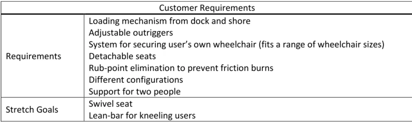
Table 2.1 Customer Requirements and Specifications Customer Requirements
Requirements
Loading mechanism from dock and shore Adjustable outriggers
System for securing user’s own wheelchair (fits a range of wheelchair sizes) Detachable seats
Rub-point elimination to prevent friction burns Different configurations
Support for two people Stretch Goals Swivel seat Lean-bar for kneeling users
2.2
Existing Designs
There is currently only one existing product on the market for adaptive paddle boards – the Onit Ability Board - which is priced at $5000. (Spinal, 2016 ) (Revolution) As shown in Figure 2.1 Onit Paddle Boards, the Onit board design has a lot of components similar to what the adaptive sports center is looking to use, including a loading ramp, and stabilizing outriggers. The cost of this board comes from the fact that it incorporates a specialized wheelchair, and ramp as well as a paddle board. These components are vital to the function of Onit’s design, while we are attempting to allow users to paddle board from the
comfort of their own daily use chair.
Figure 2.1 Onit Paddle Boards Table 2.2. Onit Ability Board Specifications
Onit Ability Specifications
Length 11’6
Weight Rating 320 lb.
Board Material Fiberglass and bamboo
Outriggers Carbon fiber
Page | 3 From research conducted on videos, pictures, and product descriptions provided on the Onit website, we were able to determine a few design components of their board, as presented in Table 2.2.. Onit uses a fiberglass, Expanded Polystyrene (EPS) foam, bamboo paddle board with carbon fiber outriggers, which can be attributed to the high price. According to their website, a combination of the EPS foam, fiberglass, and bamboo allows for a lightweight and strong board. Also, the stabilizing outriggers are removable, allowing users with different levels of experience to enjoy paddle boarding. Though Onit chose to have their outriggers made with carbon fiber, we determined that to be too costly. The board’s weight rating allows two persons to be on the board at once, which is a capability we want our board to have.
An “all-terrain surf chair”, which appears to be specific to that paddle board only, is provided with the board and there is no mention of alternate wheelchair compatibility. However, our goal is to design a paddle board that can accommodate a broad range of wheelchairs and other forms of seating such as a swivel seat or kneeling bar.
The Onit Ability Board also has an aluminum loading ramp that can be used from a dock or beach. As seen in Figure 2.1 Onit Paddle Boards, the ramp system allows the user to directly wheel the chair onto the board and into the channels where the wheels are locked down. Our goal is to build a similar ramp mechanism that attaches seamlessly to the paddle board from a beach or dock of any height, while providing quick and safe loading.
Being the only manufacturer of adaptive paddle boards currently on the market, Onit has a board that is not only costly but low in adaptability. Our group wants to develop a board that is affordable, has potential reproducibility, and can be easily used by all. Though, Onit has several components we can from which we can draw inspiration to help improve the design of our board.
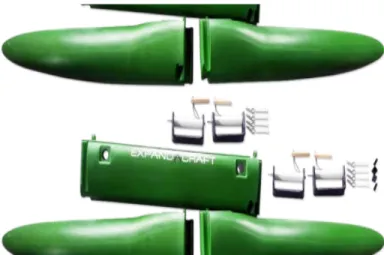
Our research also discovered a company called Expandacraft which makes outrigger pontoon systems for small watercraft. These pontoons could be adapted well for use with a paddleboard. The pontoons are made of plastic and come in interlocking sections which can be broken apart and reattached for transport. The company also offers aluminum crossbeam for attaching the outriggers to the customer’s vessel, complete with bolts and pins. A disassembled kit can be seen in Figure 2.2
Page | 4 An eight to twelve-foot-long outrigger kit, like what would be used for a paddleboard, can cost between $500 and $1000. With a kit costing almost as much as a standard paddleboard, this price could be prohibitively expensive for a person looking to manufacture their own adaptive paddleboard.
2.3
Patent Search
Our patent searches did not reveal any existing designs for an adaptive paddle board specific to our customer specifications. There are, however, several patent results related to individual components that may prove useful in the design of our paddle board.
2.3.1
Paddleboard with Removable Seat (US8752492B1)
This patent is for a twin hull paddle board with a detachable seat. Though our group is using an existing single-hull paddle board, the removable seat is related to a component we will be designing. Our paddle board needs a versatile mounting system that works for wheelchairs, stands, and any other components used to fix the user. Components 206 and 120 form a possible solution in creating a secure and quick mounting system as shown in Figure 2.3. (Harris, 2014)
Figure 2.3 Removable Seat Paddle Board Drawing
2.3.2
Vertical Bicycle Storage Rack (US20130270201A1)
Page | 5 Figure 2.4 Vertical Bicycle Rack Sketch
2.3.3
Longitudinally Adjustable Mount for a Snowboard Binding (US20010038182A1)
The snowboard rail system is a great analog to look at for an adjustable rail mounting system used in recreational sports. This design is particularly relevant because it must maintain a water tight seal so that as snow melts on the board’s surface, the core stays dry and does not become heavier, or sustain damage from rot. As shown in Figure 2.5, the mounting system relies on a set of teeth on the mounting rail as locations to lock into.(Carlson, 2004)
Figure 2.5 Longitudinally adjustable snowboard binding mounting system exploded view
2.3.4
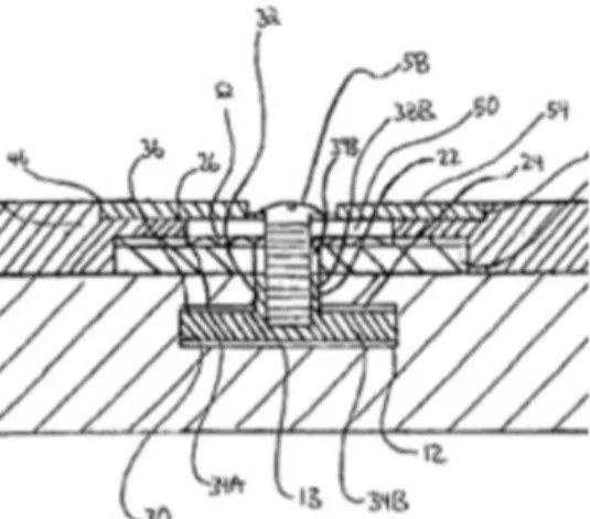
Binding Mounting System for Recreational Board (US20050248129A1)
Page | 6 Figure 2.6 Cross section of a binding mounting system installed into a recreational board
2.3.5
Adjustable Scope Mounting System (US7543405B1)
The dovetail rail mounting system used to attach scopes to rifle barrels is also applicable to the design of a wheelchair attachment system for the adaptive paddle board. Figure 2-g shows an exploded view of how a dovetail attachment system is feasible for applications that need to be longitudinally adjustable. Additionally, the system shown here may be compatible with quick-release mechanisms to reduce setup and teardown time. The important component in Figure 2.7 is the angular rail capturing mechanism and the tightening system. (Ivey, 2009)
Figure 2.7 Dovetail rail mounting system for scopes on rifles
2.4
Technical Literature
Page | 7
2.4.1
Wheelchair Manufacturers’ Reporting
Wheelchair manufacturers Karman and Quickie/Sunrise Medical both measure chairs by their seat width, measured from edge-to-edge on the seat padding between the frame supports. Karman reports that while sizes ranging from 8” to 28” are available, the standard adult sizes are 16” (small), 18” (medium), and 20” (large). Karman further reports that 90% of their users found a 20” seat acceptable (Karman Healthcare, Inc., 2017).
A spec sheet from Quickie/Sunrise Medical additionally introduced the aspect of wheel camber, or angle from vertical. Several of the lighter wheelchairs examined at from Quickie/Sunrise Medical had a slight pitch to the wheels of up to 6°. With 24” wheels this camber would widen the stance of the treads on the ground by 2.5” (1.25” per wheel) without affecting the axel width of the chair frame (Sunrise Medical Holdings, Inc., 2018).
2.4.2
Wheelchair Buyer’s Guide
In their digital guide to choosing a wheelchair correctly sized to fit the customer and their environment, the medical equipment wholesaler ADT Medequip, Inc (DBA Preferred Health Choice) says the following:
…use these formulas to determine the overall width of a wheelchair: • Transport Wheelchair: Seat Width + 3"
• Standard Folding Wheelchair: Seat Width + 8"
(Preferred Health Choice, 2018)
The team compared this information to the actual measurements of a folding Sunrise Medical wheelchair donated by a local businessman to the Adaptive Paddle project. When fully extended, the test wheelchair had a seat width of 16” and an overall width of 24”, matching the Preferred Health Choice formula. Note: that the overall width included the push rims, which protruded two inches past the actual treaded wheel. The overall tread width was only 20”.
2.4.3
Medical Case Study
A Bond University case study published in 2017, found that the benefits of stand-up paddle boarding include weight loss and improvement of quality of life. The main purpose of our project is to create a paddle board that helps provide an opportunity to be active and help those with disabilities improve their quality of life. The case study provides insight on how much of an affect paddle boarding has on people by providing several statistics of body fat and psychological health of participants over a 52-week period. This study helps define and validate the premise of the project. (Schram, Hing, & Climstein, 2017)
2.4.4
Previous Senior Projects
Page | 8 as well as additional design considerations can be applied to the new adaptive paddle board project. The team used this report as a set of guidelines and learned from their mistakes and experiences (Group 36, 2016). The report from the hydrofoil bike senior project also provided a lot of insight on how to
manufacture pontoons. This team laid out the entire process they took from shaping the foam to curing the resin which is extremely similar to the process used in this project.
2.4.5
Surfboard Foam Discussion
The paddle board Mr. Coffman provided us is a Surftech Universal Fleet Coretech board with an expanded polystyrene (EPS) foam core and layers of polymer resin and fiber glass, as shown in Figure 2.8, obtained from the Surftech website.
Figure 2.8 Detailed Material Composition of the TekEfx Paddle Board
A combination of resin and Polystyrene decrease the weight of our paddle board while maintaining the structural strength necessary for use. One main concern of this board material the propensity of foams for absorbing water. Unless the board remains completely watertight at the end of this project the water absorption and retention of the core will drastically limit its useable lifespan. This issue requires deep research at later stages of the project to ensure we thoroughly seal the board after cutting through the outer layer to make our final modifications. (Surftech)
2.5
Disability Regulations
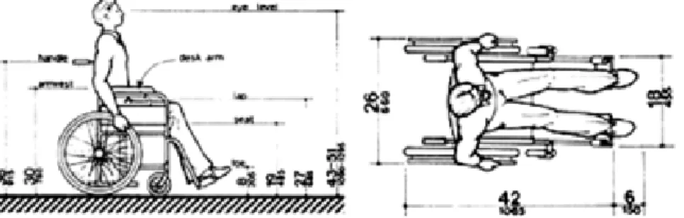
In its 1991 publication of the Title III regulation the American Disabilities Act (ADA) provides guidelines on typical wheelchair dimensions for a large adult male (Figure 2.9).
Page | 9 While these guidelines are a bit dated, they show that the general sizing and proportions of wheelchair technology has remained relatively unchanged for the last three decades. The only notable change is that the average American width preference has gone up a size from 18” to 20” (Karman Healthcare, Inc., 2017) since the ADA research of the late 80’s and early 90’s. The final design should be able to accommodate wheelchairs for decades to come.
3
Objectives
3.1
Formal Problem Statement
Surprisingly, the adaptive paddle boards for individuals with limited mobility are prohibitively expensive. Therefore, adaptive sport centers need an affordable option for paddles boards that properly
accommodate clients with various limited mobility conditions, but in particular attaches to wheelchairs. This solution is important to these centers because it offers an adventurous activity that provides a sense of achievement to the individuals.
3.2
Boundary Diagram
Figure 3.1 Boundary Diagram Sketch
Page | 10
3.3
Scope
To clearly address our problem statement, and find viable solutions, our group analyzed the current products on the market, and rated their ability to meet the demands of the user and theorizes testing methods to quantify how well each criterion is met. This process is called Quality Function Deployment (QFD).
The first step of developing a QFD chart is to define the main users. In our case these are adaptive sports centers, along with amputees, paraplegics, and individuals with motor neuron damage. Each of these users has slightly different needs and wants, and to take this into consideration, the QFD ranks each desired function for each user, allowing for weighted analysis which gives more importance to the higher importance functions.
After defining the users and their desired attributes, the next step is market research into existing products and defining tests that quantify how well each desired function is achieved. These tests are given minimum acceptable “pass” criteria. Ideally each of the existing products would be tested, but due to time and money constraints, we decided to forego this step. However, each competing product was ranked on how well they meet the functions based on user reviews, and research into the products online.
The most current version of the QFD can be seen in Appendix A. Some areas are left blank because we have not yet built a product to compare with the existing market. However, the relative weights for desired functions can be seen. These values help determine and is used as a reference of our design direction.
Table 3.1. contains a list of measurable engineering specifications to ensure that we are meeting the requirements of our sponsor and ensuring that the paddle board will be fully functional. We have established specific standards to meet and methods with which we will measure them. In the risk column, we ranked each specification with a risk to determine how difficult it would be to meet the specification. Under the compliance column, we listed the methods with which we will ensure that our design meets each specification: Testing (T), Analysis (A), and Inspection (I).
Table 3.1. Engineering Specification Table
Spec. Parameter Description Requirement [Units] Tolerance Risk Compliance
1 Tipability 200 lb/pontoon Max High T, A
2 Production Cost $1000 Max Low A
3 Time to Load 5 minutes Max Moderate T
4 Weight of Equipment 75lb Max High T
5 Outrigger Width (end to end) 10 ft -1/+2 Moderate A, I 6 Center of Gravity (longitudinally) Unchanged -/+ 7 in Moderate T, A
7 Secure wheelchair 250lb/strap Max Moderate T
Page | 11 Production cost will be estimated during the design phase to ensure that we will not go over the budget. The $1000 is our maximum budget that we will use for the retrofit.
One of the main goals is to develop a system that allows for quick loading of the user and switching of components. Ideally, we want the entire process to be under five minutes and we will measure that through continuous testing and data recording.
Our supplied paddle board has a maximum weight it can support. In order to consider a range of weights for our users, we need to keep the weight of our equipment under 75lbs. To ensure that we meet these criteria, we will perform analysis with SolidWorks and make estimated weight calculations.
The tolerance column is a reference to what the acceptable range for the specified test result is. If noted with “Max” this refers to the degree with which we can measure and be certain of the result. For
example, the cost can be derived from receipts, and labor calculations which will give an extremely accurate cost.
The risk column refers to the consequences of failing to meet the requirement. For obvious reasons, the torque test is high risk because if the board fails with a torque applied while in use, the wheelchair can become detached and sink into the body of water, essentially rendering our product useless. If the added equipment is too heavy, the board again will not float, and is therefore a high risk. Similar reasoning can be applied to the other tests to acquire the level of risk for each.
The reach of paddle strokes will affect how far our outriggers will be placed. Paddle strokes differ in length specific to the user, so we need to accommodate for a wider range, hence the adjustable length of rails for outriggers. We plan to design for roughly 7-10 feet of width for the stabilizers. The initial design will be easily modifiable in the event that our analysis does not match up with common body sizes during testing. A conceptual sketch can be seen in Figure 3.2 showing how the adjustable
outriggers function. This adjustment allows for not only the user to utilize less stabilization to step closer removing them altogether, but to reduce water and air resistance on the paddleboard to travel faster on the surface of the water.
Page | 12 The QFD in Appendix A is organized such that the needs and wants our project aims to satisfy are listed along with their relative importance to each end user. Additionally, the QFD shows testing methods for each criterion and how we define success.
4
Concept Design Development
Our team began with the base functions and customer requirements to eventually develop a chosen concept model for our paddle board. We ran several ideation sessions, took those ideas and evaluated them through Pugh matrices, developed a morphological table to combine top concepts, and ranked those top concepts to choose our final concept design.
4.1
Ideation Generation and Development Process
Our team initially held a series of four ideation sessions to brainstorm potential designs as a group, with one session led by each team member. We utilized a ‘brain-sketching’ technique in which the team members spend five minutes drawing up their initial ideas for a solution to the problem at hand. Once complete, the members each explain their ideas to the group. The process is then repeated as desired. The goal of these sessions is to generate a plethora of concepts, however absurd they are, not
necessarily just good ideas. This broad approach helps stimulate new and innovative solutions which will be audited for feasibility at a later stage. The first session focused on the broad scope of the project and served as a jumping off point for potential designs. The second session concentrated on methods of latching to the wheelchair, while the third session looked at ways of embedding an anchor into the board. The fourth session focused on both the means of stabilizing the board in the water and loading the user and chair onto the board. After discussion with our sponsor led to a change in design direction, we later held a fifth ideation session. This last session was to brainstorm ways to attach the chair to the board without cutting into the board. At this point in time previous ideas that involved modifying the board itself were abandoned. We chose to focus on designs that involved no modifications to the board but would allow for parts above the surface of the board. Therefore, we conducted a new ideation brain sketching session on this topic. The main benefits of this new design direction were not having to cut into our existing board and the versatility of being able to attach the system to different boards. The new design direction had less risk of damaging the board and would offer a greater weight capacity for the board.
After ideation, we took the concepts we deemed most feasible and put them into Pugh matrices, found in Appendix B. These matrices rate the proposed designs as superior, inferior, or the same at fulfilling the customer requirements compared to the existing product in the market. The list of requirements was taken from the QFD. Our team made Pugh matrices for four design functions: attaching our anchor base to the board, attaching the chair to the base, stabilizing the board, and loading the wheelchair. From these Pugh matrices, we selected our top designs for each function, which would later be
evaluated with a morphological table and a weighted decision matrix. The Pugh matrices compared our various ideas to the existing Onit Ability Board found on the market.
4.1.1
Attachment Frame
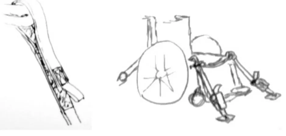
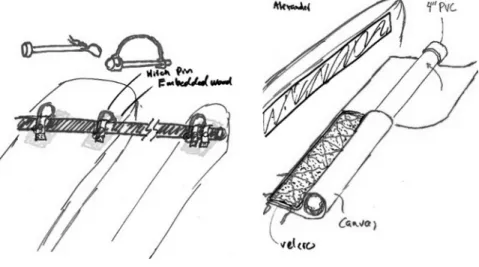
Page | 13 carbon fiber and used as the attachment point for the wheelchair. The other involved a pair of semicircular solid attachments, one on each side of the board, which would be connected by horizontal cross straps. The wheelchair would be anchored to the side attachments, which we referred to as side cups. The side cups would likely be made of plastic or PVC pipe and potentially lined inside with a soft foam material. These two harness systems are pictured in Figure 4.1 Frame with harness and Figure 4.2.
Figure 4.1 Frame with harness Figure 4.2 Side cups with harness
4.1.2
Anchor Straps
The Pugh matrices for wheelchair attachment led us to move forward with one concept of using a clamp that would go over the rim of the wheel and lock it in place. Another idea to progress with was to use ratchet straps that would hook onto the frame of the chair and anchor it in place. There would be four straps attaching to four points around the chair, as shown in Figure 4.3 . The third idea continued to consider was a similar concept the second system chosen but used Velcro straps instead of ratchet straps. These Velcro straps are seen in 4.4. We eliminated the idea of using a bungee cord system with a rubber torsion rod because we felt it would be more difficult to manufacture. We also eliminated the idea of attaching the chair from a single point under the chair as we felt this would limit our ability to change chair position on the board.
Page | 14
4.1.3
Stabilizing Outriggers
The matrices on stabilization led us to view outriggers as a strong design, which are pictured in Figure 4.5 Outrigger. They would consist of pontoons attached to outrigger poles which would be extendable and removable. We also chose to move forward with the idea of pontoons attached directly to the side of the board with Velcro and canvas, which we called side riggers. The side riggers can be seen in Figure 4.6. The last concept considered was using deep fins underneath the board to provide stability in the water, but this idea scored much lower due to concerns about the ability to launch from a beach.
Figure 4.5 Outrigger Figure 4.6 Siderigger pontoon
4.1.4
Loading Ramp
The fourth of the Pugh matrices was for the loading mechanism. One idea that scored well was a ramp with two parallel sections, one for each wheel, with hinges at two points to allow flexibility, and hooks at the end to attach to the frame. Another strong concept was again, a two-section ramp with hinges. However, this concept used a pair of arms on either side of the board and a center peg which would slot into the notch in the center of the board to hold it in place. This peg and arm design, or 3-point ramp is illustrated in Figure 4.7 Peg and arm ramp. The third design with which we would proceed was a simpler ramp that would be one section as wide as the board and easier to make.
Figure 4.7 Peg and arm ramp
4.2
Design Selection Process
Page | 15 into several overall designs, as shown in Table 4.1. In order to evaluate these designs to choose the best solution, a weighted decision matrix was used to compare the overall design outputs from the weighted decision matrix. The results of the weighted decision matrix, which can be found in Appendix B, are numerical values that represent the performance of the proposed solution based on various customer needs and their relative importance.
The morphological table included component ideas formulated in the ideation sessions that were found to be favorable to the Onit paddle board, or at least comparable. Table 4.1. shows the morphological table that produced two overall designs designated Concept 1 and Concept 2. These concepts were then put into a weighted design matrix.
Table 4.1. Morphological Table
Subsystem Concept 1 Concept 2
Attachment Frame Frame Side Cups
Anchor Straps Velcro Ratchet
Loading Ramp Full Width Ramp
Stabilizing Outriggers Outrigger
This weighted decision matrix uses each customer requirement and assigns a weight 1-5 depending on how vital the requirement is to the function of the adaptive paddle board. For example, having a positive buoyancy is weighted a 5 because it is the primary function of a paddle board; to support a person above water to enable them to paddle around. On the other hand, ease of dock loading was weighted a 2 because our primary customers will load from the shore. After weighting each
requirement, a score 1-5 was given to each overall concept based on how well the design would meet the customer need or design requirement. The final result of the weighted decision matrix was that Concept 1 met the requirements better than Concept 2, and therefore the chosen design to move forward with is an Aluminum Frame that attaches to the wheelchair with Velcro straps, and utilizes outriggers for stabilization. The chair will be loaded with a full width ramp that sits on top of the frame.
4.3
Selected Concept Design
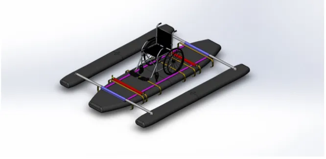
Many deciding factors went into selecting our concept design in order to meet our customer
Page | 16 Figure 4.8 Complete Paddleboard Assembly
4.3.1
Attachment Frame
The attachment frame, which will serve as an attachment to the board, will be constructed out of three main components: a longitudinal rail, a transverse box beam, and an outrigger strut housing. A full assembly of the subsystem is shown in Figure 4.9. The longitudinal rails will run 8’ down the length of the board, the transverse box beam will be 32’’, and the outrigger strut housings will be 20’’. The
purpose of the transverse box beam is to provide a strap attachment point as well as another element of rigidity to the frame. The outrigger strut housings will have a top end of a box beam cut out with a round tubing sitting into it, welded on three contact points. The struts will provide a tube for the outriggers poles to fix into and prevent significant sliding or deflection.
Page | 17 One of our concerns is the strength of the weld between each component. Though a quality weld should be more than enough to support any load that the frame will be seeing, we will be conducting
precautionary measure to ensure that the weld does not fail. In the later stages of our project when we will be manufacturing our frame, we will conduct a test to see what load our weld will fail at.
4.3.2
Anchor Straps
The anchor strap system sits on the end of the transverse box beam and connects to points along the frame of the user’s wheelchair. The function of the chair attachment system is to keep the wheelchair firmly secured to the board, even in the presence of loads due to tipping. The configuration of securing the strap to the frame is shown in Figure 4.10.
Figure 4.10 Strap Connection Configuration
The strap will sit on the underside of the inside of the transverse box beam and will be secured using a combination of nuts, bolts, and washers. The purpose of the washer will be to distribute the load from the nut and bolt over a wider area of the strap to prevent quicker strap wear and guarantee a more secure connection.
On the wheelchair side of the connection, we plan to use Velcro straps to attach to the frame of the wheelchair. Compared to ratchet straps, we felt that the Velcro straps would provide more flexibility in terms of where it can attach.
One potential problem we see arising is the failure of the strap. We plan to perform calculations to estimate the load that the strap will be seeing and load testing a sample model strap configuration to see when and where the strap will fail.
Page | 18 The main source of stabilization on our paddleboard will be from outriggers. Our sponsor requested an outrigger system that would be adjustable in length and detachable from the paddleboard. Figure 4.11 shows how our pontoons will connect to long poles which will run through the outrigger strut housing. For the pontoons, we are planning to purchase a set of outriggers online from a manufacturer. We are still unsure as to what exactly we will be purchasing, as more research is still required. Based on a rough search, we have determined many of the outriggers to be either expensive or not within dimensions to fit our design.
Figure 4.11 Outrigger Subsystem
Calculations are also still needed for the buoyancy force that will be required from each of the
outriggers in order to support any amount of tipping. We anticipate running into more issues with our design when we select exactly what outriggers we will be purchasing to use.
4.3.4
Loading Ramp
Page | 19 Figure 4.12 Loading Mechanism Subsystem
We plan on constructing the loading mechanism with sheet metal, as that would provide the greatest amount of support against loading from the user. The portion that rests near the outrigger strut and raises the ramp will be made from angled pieces of metal. The ramps will be connected with several hinges which will allow free rotation. The top surfaces will also be coated in a layer of truck bedliner to provide grip and additional corrosion resistance to the ramp.
One large concern for this ramp is the weight of the design. With the entire ramp constructed from metal, there will be no doubt that it will be heavy. This could potentially make it difficult for the people helping load the user to set up the ramp quickly. Further calculations and tests will be necessary to determine how much material can be removed to reduce weight while maintaining the same strength.
4.4
Preliminary Analyses
Page | 20 Figure 4.13 Transverse beam critical failure location (in orange)
An initial structural stress calculation for a worst-case bending scenario (found in Appendix C) indicates that a $15 2”x1” aluminum box beam would require over 1200 lbs. of force from the user to
compromise its integrity. This analysis reassures us that we can build a suitable robust frame of this design at a reasonable cost.
4.5
Risks and Challenges
Our Design Hazard Checklist (found in Appendix D) shows that our design has very few safety concerns. The main potential hazard is that parts of the design could pinch or chafe against the user. The straps attaching to the chair are the chief concern. To avoid any risk of pinching we will make sure that all the strap attachments are secured well away from the user, preferably on the underside of the chair. The risk of chafing against their seat can be kept relatively low because our design will keep the user in their own personal wheelchair, which should be well suited to their comfort. By not transferring the user between chairs we can minimize the risk of chafing due to a poor chair fit. We are also concerned about the danger of hard attachments to the board that could cause injury to the user. If the user did fall from their chair, we would not want them to hit their head or any other body part against the hard frame on top of the board. We intend to cover the hard parts of the frame with a foam mat in order to alleviate this concern. Drowning is a natural concern with any aquatic activity, but the risk is low for in our case. The occupant will be wearing a life vest and will in no way be strapped into the chair or otherwise constrained. Using our design is not significantly more dangerous than an able-bodied person using a standard paddleboard.
Page | 21 board are a major reason why we elected to go with a harness system that does not cut into the board. A harness system eliminates a major challenge that could have caused our design to fail. That being said, we must still take great care that any bolts or other parts of the frame do not damage our board
accidentally. If the frame scratches or cracks the board surface the issue of waterproofing will become a problem once again.
We are also concerned about the potential issues of rust or corrosion. The board will experience frequent contact with water during its normal usage, and so all components must be able to withstand submersion in water without being compromised. The materials for parts must be carefully selected so that they will not be heavily damaged by rust or corrosion from exposure to water. If parts rust or corrode they could fail during use and potentially lead to harm to the user.
Our team also must determine how the outriggers for our board will be manufactured. There are options available to purchase but they tend to be expensive. If we decide the market options are not worth the money, we will need to build our own outriggers. We will have more clarity on this issue after discussing it with our sponsor. Our sponsor can decide if they are willing to budget for high quality, professionally manufactured outrigger pontoons or not. If we must build our own, we need to do more research on how to do so. Research topics for this would include materials selection, potential
adhesives, and methods of waterproofing.
5
Final Design
This section includes detailed design descriptions of the attachment frame, anchor straps, outrigger stabilization, and ramp loading subsystems updated from the Critical Design Review (CDR). Detailed parts, Bill of Materials (BOM), dimensioned drawings, and costs are included.
5.1
Final Design: Subsystems and Components
From the CDR, modifications and improvements were made with regards to safety, weight, and
Page | 22 Figure 5.1 Exploded view of overall design assembly
The material of the loading ramp, which was initially metal sheets, was replaced with High Density Polyethylene (HDPE) sheets. The middle section was also shortened as our ramp test (Appendix H) revealed that there was too much deflection. The pontoons are now manufactured by our team, as there were not any products on the market that met our specifications. Lastly, D-ring pins were chosen as a quick way to secure the stabilizing outrigger system.
5.1.1
Attachment Frame
Page | 23 Figure 5.2 Exploded model of frame subsystem
The longitudinal rail is an 8’ x 2’’ x 3/8’’ extrusion, the transverse box beam is 32’’ x 1’’ x 2’’ with a 1/8’’ thickness, and the outrigger strut housing is a 1.8’’ box beam with a 3/16’’ thickness. All components will be 6061 T6 Aluminum, which we have found to be the best grade in terms of water and corrosion resistance. The components will be joined with a lap weld where the edges of each part meet (details of the manufacturing plan can be found in section 6). The rigid, rectangular frame design will minimize any possibility of the frame slipping over any edge of the paddleboard.
We decided on altering the outrigger strut housing design to a box beam for ease of manufacturing. Our initial design was composed of a round tubing welded into a three-faced box beam. The new design will eliminate an additional concern for failure at a weld as well improve ease of reproducibility. We also drilled a ¼’’ hole on each front and back face of the housing to fit a D-ring. The round poles extending to the pontoons will have a minimal clearance fit into the square strut housing to ensure that there is no “wobbling” of the poles. The design for the transverse box beam has remained unchanged as it would provide the most structural rigidity.
Page | 24 Figure 5.3 Exploded view of frame and paddleboard
With a combination of the NRS straps and the rigidity of the frame, the user and its wheelchair will be able to remain fixed on top of the paddleboard without concern of the frame slipping off.
5.1.2
Anchor Straps
On top of the transverse box beam sits the anchor straps that will be responsible for connecting the frame to the wheelchair. Since CDR, we have kept the location of the strap to the top of the transverse beam to eliminate potential wear from the edge of the beam.
Page | 25 To meet the requirement of accommodating a variety of wheelchair sizes and designs, a Velcro strap system is utilized to allow continuous adjustability of the loop length that attaches though the frame of a wheelchair. We were able to manufacture our own Velcro straps and are confident based on the quality of sewing that we produced a quality strap.
Figure 5.5 Velcro strap attachment to chair
As displayed in Figure 5.5, Velcro is sewn on to one side of the nylon webbing to allow a secure
temporary loop to be formed around a member of the user’s wheelchair. The Velcro is secured through a buckle that will connect to the nylon strap portion that is mounted to the frame. The Velcro also has a fair amount of surface area of contact to ensure the method of securing the straps in place will not fail under proper use.
A tensioning buckle is included on each strap to allow for pre-tensioning. This eliminates the possibility of slack in the attachment straps and ensures a tight clamping force between the board and the wheelchair.
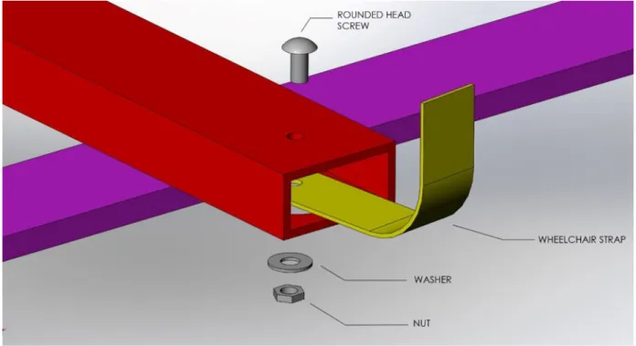
On the side of the strap that attaches to the aluminum frame, the webbing is captured between a fender washer and the rectangular aluminum tube. The fender washer helps evenly distribute the clamping force over a wider area of the strap. An exploded view of the sub assembly can be seen in Figure 5.4. Each of the four attachment points will have a 3/8’’ bolt, two 3/8’’ washers, a 3/8’’ fender washer, and a nut.
A main concern for the strap connection design was strap failure under a tensile load. We ran the strap configuration through a tensile tester and in each test case, the strength of the low-budget test webbing exceeded our predicted calculations for worst case scenario load. This test eliminated any concern for strap failure due to the strap and connection withstanding more force than the worst-case loading scenario. More details of the test and predicted load can be found in Appendix J.
Page | 26
5.1.3
Stabilizing Outriggers
Our stabilization outriggers will consist of two pontoons mounted at either end of the aluminum struts that extend from the frame. These struts will pass completely though the pontoons, allowing for the adjustment of the pontoons along their length. The location of the pontoons will be fixed with D-ring pins.
To ensure adequate room for the end user’s paddle stroke and sufficient buoyancy, the pontoons will be 10’ x 8” x 8”.As shown in Figure 5.6, they will follow a hydrodynamic curve reminiscent of a sculling boat.
Figure 5.6 CAD model of outrigger pontoon
After discussing manufacturing options with local fiberglass expert and former Cal Poly shop director George Leone, we selected a polyurethane (PU) foam and UV-cure polyester resign design. The pontoons consist of a 1 ½” wall of PU foam and three layers of glass cloth saturated with resin and topped in a wax ‘hot-coat’ layer to provide a complete cure.
From George Leone’s advice and the process documentation of the 2013 Cal Poly senior project ‘Human Powered Hydrofoil’ we concluded that it would be feasible to assemble a layered foam design using the more readily available 1” sheets of PU foam instead of a solid 10’ block. We cut individual layers out of PU foam and adhered them together with a water-activated foaming glue – Gorilla Glue – before sanding to shape and glassing.
Page | 27 To validate our process and develop a familiarity with fiberglass George Leone invited us to his
workshop in Atascadero and walked us through the process of developing four test samples of fiberglass on a scrap surfboard core. Additionally, the results of our tipability test in Appendix G show that the outrigger system holds up extremely well to large loads and cannot flip the paddleboard.
5.1.4
Loading Ramp
After considerations of our previous ramp, we decided to switch to an HDPE double ramp which cuts down on weight and provides more strength (calculations of HDPE strength can be found in Appendix K). We modified the lengths of the middle section of the ramp to reduce deflection and added corners to both sides of each ramp to ensure a safe loading for the user.
Figure 5.7 CAD Model of Ramp
Page | 28 second and third rail sections measures 10” x 30” x 1”. This crossmember is supported by two support blocks which raise it off the board surface. These blocks are angled and cut from sections of rubber blocks. One block rest under each side of the crossmember. A pair of smaller angled support blocks sits under the third ramp sections. The support blocks are connected to the boards with #8 x 2” construction screws.
Steel hinges are used to connect the ramp sections. Two 3-1/2” wide hinges are placed side by side on a single rail section at each connection. The hinges are screwed into the ramp with #8 x 1-1/4”
construction screws, and eight hinges are used in total. Layers have been removed from the boards to allow the hinges to sit flush with the rest of the ramp surface. The ramp will be coated with a sealant to protect against water damage and a layer on the upper faces to provide additional traction.
The purpose of the three-section hinged ramp is to provide versatility and portability. The middle section can pivot to slope upward and downward, allowing for loading from a shore or from a dock. The sections at the beginning and end will sit firmly on the initial loading surface and the board itself, respectively. These sections provide stability during loading and a smooth transition on and off the ramp. The crossmember at the beginning of the ramp extends wide to either side of the parallel rails. A person who is assisting in loading the user onto the board places their feet on either end of this
crossmember. The weight of them standing on the member helps keep the ramp in place during loading. Once on the ramp, the user must be able to get over the protruding parts of the board frame. For this reason, the last sections of the ramp are supported by blocks which sit on either of the housing tube for the outrigger struts. The support blocks keep the ramp raised above the frame so the user can roll easily over the housing tubes. The ramp then angles the user smoothly down onto the board surface. The L-shaped brackets running along the edge of the ramp function as a wall that prevents the user from rolling sideways off the ramp during loading.
Our ramp design was tested by building a full-scale prototype out of plywood and loading a person in a wheelchair onto the paddleboard. The test, which is discussed in greater detail in Appendix G, proved that the design could effectively and comfortably allow a user to load themselves onto the paddleboard with minimal assistance. The entire process was simple and expedient.
Our loading ramp provides a versatile way in which users can load themselves onto the board. Our design is lighter, more compact, and more rigid than previous revisions.
5.2
Safety, Maintenance, and Repair Considerations
From our Design Hazard Checklist (found in Appendix D) we can determine that our planned final design has few major safety concerns. Our worst-case scenario would be a situation in which the user falls from the wheelchair and injures themselves by hitting a body part against one of the hard metal components of our design. In order to prevent this a layer of soft foam matting will be used to cover hard raised surfaces and sharp edges wherever possible. Additionally, the board will be used on deep water, so the risk of drowning must always be considered. However, we deem the risk of drowning with our design to be low. The user will not be strapped into their chair, so they would not be trapped underwater in the event of capsizing. The user will also be wearing a life jacket and will generally be supervised.
Page | 29 can be found in Appendix D. The straps connecting the wheelchair to the frame should be inspected frequently to ensure that the strap is not tearing at the point where it is bolted to the frame. The bolt should also be examined. If it proves necessary to replace either part, the strap can be easily unbolted, and the system then reassembled with whatever new or repaired parts are required. The ramp is at risk of suffering damage from water or from scraping or bumping against rocks and beaches. The wood of the ramp may need to periodically be resealed against water damage. Components or even the entire ramp may need to be replaced from time to time. If individual components need replacing, they can be easily unscrewed from the rest of the assembly and new components can be simply installed. If the entire ramp needs to be replaced, a new one would be cheap and relatively easy to manufacture. Because the entire system will be frequently exposed to water, all metal components should be checked for rust or corrosion. Small components such as the hinges and screws of the ramp, the bolts, nuts and washers attaching the chair straps to the frame, and the pins for the outrigger struts, can all be easily and affordably replaced. Replacing or repairing any part of the welded frame itself would prove far costlier and more difficult. As such, great care is taken to select frame materials that will be as resistant to water damage as possible.
5.3
Cost Analysis
A cost estimate of all the components of our design was compiled to ensure that our product would not exceed the budget of our sponsor. Table 5.1 shows the cost summary and a subtotal cost of each subsystem. A comprehensive table of components, costs, part numbers, and vendors can be found in Appendix E.
Table 5.1 Materials cost summary
Subsystem Cost
Stabilizing Outrigger $2680.11 (foam purchased) $1180.11 (foam donated)
Loading Ramp $450.57
Attachment Frame $148.82
Anchor Straps $57.80
Total $3337.3 (foam purchased) $1837.3 (foam donated)
At a total cost of $3337.3, our project will have a low budget relative to that of the Onit Ability Board. The polyurethane foam will be the most expensive component of our design, priced at roughly $1600 for the construction of both pontoons. We have looked into the possibility of having foam donated to our team and there are currently two potential suppliers.
George Leone, the advisor of Cal Poly’s Human Powered Vehicle Team, has offered to donate some foam that he regularly picks up from a manufacturer in Southern California. However, the date at which he is going is still undetermined. Jim Cullins, one of Cal Poly’s Machine Shop advisors, also mentioned the possibility of donating some of the foam that the shop currently has in inventory.
6
Manufacturing Plan
Page | 30 flowchart. Most notably, the frame must be completed before the pontoon’s metal inserts can be
installed.
Figure 6.1 Manufacturing system flowchart
6.1
Aluminum Frame System
The frame is constructed from 6 main aluminum pieces which are described in Table 6.1. Table 6.1 Aluminum Frame Components
Name Length (in) Width (in) Height (in) Wall Thickness (in) Quantity
Longitudinal Rails 96” 2” 3/8” N/A 2
Transverse Box Beam 32’ 2” 1” 1/8” 2
Strut Housing 20’ 2 ½” 2 ½” 3/16” 2
Strut 120” 2 ¼” N/A 2
The first step in manufacturing the frame was to cut the metal stock to size. The longitudinal rails were purchased at the correct length, while the remaining aluminum pieces were cut to length in Mustang 60 using a chop saw. All aluminum pieces were also deburred to remove sharp edges. Next, the holes that the frame attachment straps are bolted to the transverse box beams were drilled. On the top on the box beams, a 3/8“ holes were drilled centered on the centerline of the box and 2” from each end. On the bottom, 2” diameter holes were drilled in the same locations. These holes were then deburred to break sharp edges. This process of preparing the aluminum pieces took about 6 hours of work over two days.
Page | 31 Once the frame was properly fixtured, the weld locations were pre-heated with an oxygen-Acetylene torch set with a neutral flame to ensure heat was not conducted away from the weld too fast, while welding. These welds were performed with a Tungsten-Inert Gas (TIG) welding system set to 130 Amps AC using a green tipped tungsten electrode. There are four welds at each intersection of components. Welds between the transverse box beam and the longitudinal rails are represented in blue in Figure 6.2 where two welds are on the top of the frame, and two welds are on the bottom.
At the ends of each longitudinal beam, the square tube strut housing was welded in a similar fashion, however for the front and back ends of the frame create slightly different weld geometries due to the end of each component at the intersection. To ensure the parallelism target was achieved, the two top strut housing welds at each corner of the frame were completed to guarantee that the transverse box beam welds do not distort the frame before the strut housings are fixed in place. Then the remaining transverse box beam welds located on the top of the frame were completed. Next, the frame was flipped over, and the remaining welds were completed. Finally, the strut housings had a though hole drilled through their centers on the vertical walls. These are used to attach the struts to the frame with D-pins.
The final step on the frame was to create the struts. These were cut from one 20’ long aluminum tube. Then, two through holes were cut 2” from the ends through the center using a hand drill. These are for attaching the struts to the pontoons. Another hole was drilled in the center of the strut at 90 degrees from the end holes to attach to the frame. The process of creating the frame took 35 hours spanning over two months due to scheduling difficulties.
6.2
Loading Ramp System
Table 6.2 Purchased Ramp Materials
Purchased Material Size Material Quantity
Plywood sheet 4 ’x 4’ x 1” HDPE-UV 1
Small Screw #8 x 1-¼" Stainless Steel 36 Long Screw #8 x 2" Stainless Steel 20
Hinge 3-½” Stainless Steel 8
Angle Support Beam 2” x 2” X 6’ Aluminum 2
Support Block N/A Plastic 2
Page | 32 Table 6.2 is a condensed list of the purchased materials used in the design of the ramp system. The surface that the user’s wheelchair will roll on is made out of UV resistant high-density polyethylene (HDPE). This sheet will have the appropriate size of rolling surfaces for the ramp cut out of it. These sizes are listed in Table 6.3. These sheets are to be cut out using a table saw in Mustang 60. The aluminum angle support beams are cut in half to create four sections that are 36” long on a chop saw.
Table 6.3 HDPE surface components and sizes
HDPE Component Size Quantity
Foot Pad Cross Struts 3” x 48” 1
Unconstrained Surfaces 8” x 36” 4
Transverse Middle Surface 3” x 30” 1 Elevated Transverse Surface 10” x 30” 1
Boardside Surface 12” x 22” 2
Once the four unconstrained ramp surfaces have been made, aluminum angle support beams are screwed onto the length of both sides of two of them to form channels that reinforce the ramp section against bending. This is achieved by predrilling the aluminum and screwing the L bracket straight onto the bottom of the board.
To ensure that the ramp components are squared to 90 degrees, a large construction square is used to align parts before they are attached. All holes for the screws are pre-drilled with a 3/32” drill bit before being screwed in with battery powered hand drill. The 90 degrees Overall, the construction of the ramp prototype made from plywood took 25 hours to build, including material sourcing. Therefore, the estimated time for the manufacture of the HDPE ramp is 20 hours to account for gained knowledge and experience in building the same structure out of a different material.
6.3
Stabilizing Outrigger System
This section explains the detailed steps taken to manufacture the stabilizing outrigger system. This includes CNC machining for the foam, adhesion of the cuts, and the entire fiberglassing process to strut housing reinforcement.
6.3.1
CNC Machining
To cut the layers of the pontoons that are to be glued together, a CAD model of the pontoon was created on Fusion360. This model represented the shape of the pontoon prior to 3D contouring or rounding of edges; it was essentially an extruded shape of the top view. This model was then sliced into 1” thick layers. These layers were then adjusted to allow for a hollow center of the pontoon, while keeping the nose and tail solid to retain the strength needed to transfer load to the struts. Since the hollowed geometry created thin wall made of strips in every layer, the strips were replaced by vertical sheets to simplify the process. Once the layers had been appropriately modified, the required foam pieces for each section were arranged onto a 4’ x 8’ x 1” sheet in Fusion360. The required pieces for both pontoons required three sheets. Using Fusion360 for its useful function of adding tabs around 2D contours in the generation of G-Code, a toolpath was created for each of the three sheets.
Page | 33 cut out of the sheet by slicing through the tabs with a box cutter. The pieces were then sprayed off with compressed air and had the remnants of the tabs removed in preparation for the adhesion step. The CNC phase of the pontoon creation took 32 hours of work over two weeks due to scheduling conflicts and machine availability in the hangar.
Figure 6.3 ShopBot prior to cutting a sheet of foam
6.3.2
Adhesion
This phase covers the process of joining all 2D components of the pontoons into a basic 3D shape with hard 90-degree angles. This process was completed in the senior project room in the Bonderson Project Center. On a flat surface, the layer components of foam were aligned, and a THIN layer of Gorilla Glue was applied onto one sheet, spread until the glue color was almost undetectable. Then, using a spray bottle the face of the next layer was moistened and evenly distribute moisture across sheet. At each layer, the sheets of foam were aligned, and checked to ensure the adhesive was in contact with both surfaces to be joined. After all layers are aligned and in contact, a flat plank was placed across top of foam stacks and 5-gallon buckets filled with water were placed on top to ensure adequate pressure on expanding glue. Since the hollow inside of the pontoon needs to be reinforced later with fiberglass composite, the top layer was left off to allow access. The top layer pieces were glued together and held together using screws. The excess foaming glue was scraped from seam faces as it emerged to ensure a quality surface finish. Allow 24 hours to cure. The adhesion phase took 60 hours including the curing time.
6.3.3
Model Shaping
Page | 34 Figure 6.4 Sanding interior radii with a disk sander
6.3.4
Fiber Glass Reinforcing
This phase includes the processes used to complete three layers of fiber glass on the exterior and three layers of fiberglass on the interior, as well as on the top layer. The overall process path for one pontoon is outlined in the flowchart in Figure 6.5 Pontoon Fiber Glassing Flowchart. This phase was also
completed at an off campus composite workshop. Since the polyester resin used in the lay-up was UV curing, a workspace that is completely blocked from sunlight while still well ventilated is required.
Figure 6.5 Pontoon Fiber Glassing Flowchart
Page | 35 Figure 6.6 Mock lay-up of an external layer of the bottom
Once the cloth is draped over the foam in the correct location, the wet lay-up process begins. The UV curing polyester resin was applied to the cloth and spread from the center at 90 degrees to ensure minimal cloth shifting and wrinkles. If a wrinkle developed, the nearby cloth was pulled at 90 degrees to the wrinkle to remove it. Continue adding and spreading the resin until the cloth is saturated (when the cloth appears transparent). An example of a saturated layer can be seen in Figure 6.7. Once the first layer is saturated, expose the lay-up to sunlight for five minutes per side, or until the resin tacks. Then repeat the wet lay-up process for the remaining layers on the section of the pontoon being fiber glassed. After the final layer on the exterior surfaces, an extra layer of polyester resin mixed with a hot-coat wax was added to allow the polyester resin to fully cure and allows the surface to be sanded.
Figure 6.7 Exterior layer wet lay-up with excess hanging down
Page | 36
Figure 6.8 Removing Excess material with the reciprocating saw and disk sander
The interior of the pontoon was then fiber glassed using the same techniques for two layers. The excess material was again removed to create a flat surface on the top of the bottom section of the pontoon to glue the top layer onto. These surfaces did not require a hot coat. The process of coating the interior is shown in Figure 6.9.
Figure 6.9 Mock lay-up of the second interior layer
Page | 37 Figure 6.10 Un-glassed top layer glued on the bottom section
The cloth sections used to cover the top of the pontoon draped over the side walls for a minimum of 3” in all places to ensure a strong connection. Once top had been reinforced by three layers of fiberglass and fully cured using hot coat, the final step of removing excess material began. This step included removing all sections of fiber glass composite that were not flush with the pontoon. This phase of manufacturing the pontoons took an estimated 350 hours of work over seven weeks between five people.
6.3.5
Strut Insert Installation
This phase includes all process used to attach the aluminum inserts onto the pontoon. Then, once the pontoon was fully cured, the next step is to drill holes through the pontoons 8’ apart and 3 ½” from the top of the board. This is where the metal inserts are installed. This was done by using a drill press and a 2 ½” arbor drill. Two levels were used to assure that the pontoon was positioned such that the holes were square and parallel. This step was completed at the Mustang 60 machine shop.
The remaining steps were completed at a composites workshop. The holes were adjusted for using a file to ensure the metal inserts fit in place. Then, each of the metal inserts were sanded to rough up the surface, allowing superior adhesion. After sanding the metal inserts, they were cleaned using denatured ethyl alcohol to remove any debris from the surface and then etched using and phosphoric acid. This created micro-pitting to improve the adhesion between the epoxy and the metal. It is important to wear a respirator and chemical shield when handling these chemicals for personal protection.
Page | 38 were concentric as the epoxy cured and fixed the inserts in place on the pontoons. The epoxy was then allowed to cure overnight in this setup position.
After aluminum inserts were fixed in place, the area surrounding the inserts was sanded to allow the reinforcement layers of fiberglass and carbon fiber to adhere properly. At this point, epoxy was used to wet the strip of carbon fiber which was then wrapped around the two sides of the insert in a figure-eight pattern for three layers and rectilinear for two layers as shown in Figure 6.11.
Figure 6.11 Carbon fiber reinforcement pattern
The reinforcement pattern for the fiberglass layers accounted for six to seven layers in the surrounding area and was laid up in a variety of patterns as shown in Figure 6.12. The phase of installing the inserts took 150 hours between five people and four weeks.
Figure 6.12 Fiberglass reinforcement patterns