Sharif University of Technology
Scientia IranicaTransactions A: Civil Engineering www.scientiairanica.com
A new model for calculating impact force and energy
dissipation based on the CR-factor and impact velocity
H. Naderpour
a;, R.C. Barros
band S.M. Khatami
aa. Faculty of Civil Engineering, Semnan University, Semnan, Iran. b. Faculty of Engineering, University of Porto, Porto, Portugal.
Received 17 August 2013; received in revised form 27 January 2014; accepted 7 July 2014
KEYWORDS Impact; Coecient of restitution; Velocity;
Dissipated energy; Damping.
Abstract. Many researchers have studied building pounding to calculate the dissipated energy and impact force between two buildings during an earthquake. In this paper, a new equation is proposed to measure the impact force and energy dissipation. The results based on the proposed equation are compared with the results of available equations. Using a suggested link element, a new formula is presented to calculate the impact force and energy dissipation. In order to evaluate the results of dissipated energy, a new relation between CR and impact velocity is also suggested. Since there is a need to have a reference curve to select impact velocity, based on the coecient of restitution, several impact velocities and CRs were evaluated. By using the latter curve, results could be evaluated. A new equation of motion is assumed to select the best impact velocity and coecient of restitution. Finally, based on the coecient of restitution and using the steady-state response of a single degree of freedom system, due to external force, a new equation of motion is suggested to calculate the impact damping ratio.
© 2015 Sharif University of Technology. All rights reserved.
1. Introduction
Structural pounding, which may occur during an earth-quake between two adjacent buildings with dierent dynamic characteristics, has been an interesting re-search topic during the last few decades in the eld of earthquake engineering. Most researchers have used numerical methods to simulate the problem of earthquake-induced pounding between adjacent build-ings [1]. All this research was carried out based on building pounding with dierent topics. Anagnos-topolos [2] was among the rst researchers to explain possible dangers due to building pounding. Between them, the 1985 Mexico City earthquake was the source of excitation which caused severe damage to buildings. Several reports showed that at least 15% of buildings
*. Corresponding author. Tel.: +98 231 3354134; Fax: +98 231 3354136
E-mail address: [email protected] (H. Naderpour)
damages were due to the impact of adjacent buildings. Investigation of building pounding has been divided into two parts: experimental tests and numerical anal-yses. In this regard, Papadrakakis and Mouzakis [3] conducted shaking table experiments on pounding be-tween two-story reinforced concrete buildings without separation distance under earthquake records. Two steel buildings, with three and eight stories, were tested by Filiatrault using a shaking table [4]. The tests were carried out with two dierent gaps, zero and 15 mm. The experimental results were compared with analytical predictions based on the linear elastic spring theory. The comparisons showed that acceleration at the contact level was not well predicted. Watan-aba and Kawashima [5] investigated the pounding of distributed masses to model colliding bridge decks. Cole et al. [6] indicated that building pounding and its impact depend on the structural properties and collision velocity of both buildings. They suggested a plan to control the impact. They determined the
theoretical maximum collision force for a system with two distributed masses. Velocity, mass and stiness at the time of impact have a relationship, and the number and magnitude of the impacts depend on these three causes. Barros and Khatami [7] addressed some common misrepresentations in the Iranian earthquake safety codes on the issue of the separation distance required between two adjacent concrete buildings under near-fault ground motions. In numerical analyses, link elements are located between the two investigated buildings. Komodromos et al. also took advantage of link elements extensively in their research [8].
Barros and Vasconcelos [9] investigated building pounding between two adjacent concrete buildings by numerical analyses. They presented the results of analyses using dierent stiness and damping ratios. Two concrete buildings, with eight and ten stories, have been modeled by Raj pant and Wijeyewickrema [10]. Dierent types of spring with dierent stiness, or various dampers with dierent damping ratios, have also been used in recent numerical studies at FEUP by Cordeiro [11] and Vasconcelos [12] in their parametric studies of pounding between adjacent buildings. Barros and Khatami [13] estimate the eect of damping ratio on the numerical study of impact forces between two adjacent concrete buildings subjected to pounding. In yet another study, Barros and Khatami [14] compared results of two SDOF frames with dierent link elements based on mathematical relations. In some of their analyses, structures were modeled as SDOF systems, and a collision was simulated using linear visco-elastic models of impact force.
Many researchers have represented several math-ematic relations to simulate kinetic energy loss. They have suggested dierent formulas in terms of damping coecient, and developed a reference relation to get the best equation of motion. In this paper, based on a cyclic process, a new damping coecient is suggested to calculate impact force, and is checked to conrm dissipated energy.
2. Impact philosophy
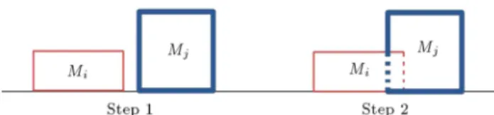
Investigation of building pounding can be addressed in two dierent paths: experimental analyses and analytical analyses. To measure the impact force dur-ing collisions and the lateral displacement of adjacent structures, software is needed to dene a specic link element at the connection level between the buildings analyzed. These link elements can be signicantly dierent, so as to insure a complete agreement between analytical and experimental results, based on type of link element. Mathematical equations corresponding to modeling by distinct link elements can be calculated by dierent approaches. The main concepts used on link elements correspond to the appropriate use
Figure 1. Schematic impact model between two bodies.
Figure 2. Schematic SDOF model.
of gap, spring and damper in them. As periods of the adjacent colliding buildings are conceptually dierent, the link elements should be able to allow and translate the dierent behavior of buildings during seismic excitations [13].
In the dynamics of structures, the explanation and understanding of the impact model focus on the usual case of two bodies. The impact forces and the consequences between two colliding bodies (Figure 1) depend on their mass and acceleration.
3. Dynamic model
Two special building cases of an original n-building formulation subject to earthquake excitation are in-vestigated. This captures the essence of more general response formulation by allowing the examination of both interior and exterior buildings. As shown in Figure 2, the adjacent buildings were modeled as a Single Degree Of Freedom (SDOF) system, with lumped masses, m1 and m2. There is a distance
(d) assumed between two adjacent buildings. The stiness of the two buildings are k1 and k2, and the
linear viscose damper constants for the buildings are c1 and c2, respectively. The impact between the two
buildings was modeled by introducing a spring and a linear viscose dashpot between the colliding buildings. The stiness of the spring between the buildings is s. these elements act only when a collision occurs. The coecient of damper has been shown by c.
In order to describe the impact between two colliding bodies using mathematical equations, the model in Figure 3 can be equivalently modeled as the response of a SDOF system.
Figure 3. Equivalently model of SDOF model.
collided masses. The equation of motion of this SDOF system is written as:
mu + c _u + ku = f(t); (1) where u is acceleration, and _u and u are the velocity and lateral displacement of the system, respectively. All mentioned options are assumed to be linear in order to conveniently search the approximate relationship between velocity and lateral displacement using the knowledge of structural dynamics. The spring con-stants can be obtained as a function of the stiness of the colliding buildings.
The dynamic equation for the pounding between single degree of freedom systems can be written as:
m1 0
0 m2
u1
u2
+
c1+ c c
c c2
_u1
_u2
+
k1+ s s
s k2
u1
u2
=
f1
f2
: (2)
4. Link elements
4.1. Linear impact model
The rst investigated model is based on a linear impact spring, which provides an elastic impact force on the link element, and simulates impact force using linear curve stiness (Figure 4). The equation of the contact collision force during pounding, evaluated by the linear elastic model, is given by:
Fc(t) = kk:(t); (3)
in which kk is the stiness of the linear impact spring,
and (t) is the lateral displacement of the colliding bodies.
In this model, the numerical value of impact force is based on a linear constant stiness, which cannot be accurately determined, considering that the characteristics of the studied buildings are dierent and that they also provide axial stiness for the distinct impacts. This model of the link element also is not
Figure 4. Linear elastic model.
Figure 5. Hertz damped model.
able to calculate energy losses during impact, which constitutes the main disadvantage of the linear elastic model.
4.2. Nonlinear impact models
The impact model between two bodies during an earthquake has been shown using a spring and damper, which are located parallel to each other. The expla-nation of the impact model focuses on two structures next to each other when they collide during seismic excitation (Figure 5).
The impact force between two bodies depends sig-nicantly on collided masses, velocity and acceleration. In this part, some used models are demonstrated to get a better image from contact.
To calculate the value of the energy dissipation, some researchers have suggested dierent relations to simulate the damping ratio. They have tried to get the most appropriate assumption for evaluating dissipated energy during collisions. A summary of previous stud-ies about the impact damping ratio of pounding shows that the suggested formula by Anagnostopolus [1] and two represented formulas by Jankowski [15] are based on the Coecient of Restitution (CR) and calculating the impact damping ratio by mathematical relations. The coecient of restitution is a factor that simulates a relation between velocities before and after collision. This relation could be written as:
0 < CR = vvbefore
after < 1: (4)
As shown, the coecient of restitution is calculated to be in the range of 0 and 1. If CR becomes equal to 0, collision is perfectly plastic, and if CR becomes equal to 1, collision shows an elastic behavior.
4.2.1. Kelvin model
The rst relation of the impact model is the Kelvin model. This model was proved by a linear viscoelastic impact model, in order to calculate energy loss during impact. In this model, impact force at time t is simulated by the following equation:
Fc(t) = kk:(t) + c _(t); (5)
where kk is stiness, c is the impact viscous damping
coecient, (t) is lateral displacement and (t) is relative velocity between the lumped masses in contact at time t. In this equation, the impact viscous damping
coecient, c, is related to the coecient of restitution, CR, which is explained by:
c = 2 r
kkmm1m2
1+ m2; (6)
= p ln CR
2+ (ln CR)2: (7)
In the above relation, c depends on , which has been described by the second written relation. CR is a vector from 0 to 1, which describes elastic and plastic impact and is explained in the next part. This formula was based on the assumption of an equivalent SDOF dynamic system that represents two bodies in contact and the conservation of energy before and after impact.
4.2.2. Nonlinear viscoelastic model
To improve the impact model, Jankowski [15] presented an idea, wherein a nonlinear viscose damper is located parallel to the spring in order to absorb the energy dissipation mechanism. The equation of the nonlinear viscoelastic model can be written by:
Fc(t) = kh:(t) + ch_(t); (8)
ch= 2
r kh
p
(t)mm1m2
1+ m2; (9)
= p
5 2
1 CR2
CR : (10)
4.2.3. Hertz damped model
The most important used relation to calculate the impact force and dissipated energy is called Hertz Damped, as written in a general form below:
Fc(t) = kh:(t)n+ c _(t): (11)
The second term of the mentioned formula describes the impact damping coecient, which is calculated by c = :(t)n.
In recent years, Ye Kun [16] suggested two mathe-matical formulas for the estimation of impact damping based on Coecient of Restitution (CR), stiness of spring (k) and impact velocity (vimp).
In order to evaluate dissipated energy during impact, Lankarani [17] suggested a mathematic rela-tion to calculate the impact damping ratio, which is determined by:
= 3kh(1 CR2)
4vimp : (12)
By using a SDOF system, Ye Kun (2008) [16] assumed that the damping coecient and stiness of equivalent are linear to get a relation between lateral displacement
and velocity. He considered the momentum and energy balance between the start and end of the collision to be equal. By this assumption, he suggested a new relation to calculate the impact damping ratio, which is written by:
= 3k2:CR:vk(1 CR)
imp : (13)
In order to improve the mentioned formula, a developed equation was noted by Ye Kun (2009) [18]. Based on a mathematical relation and considering a more accurate method, he calculated a new equation for the impact damping ratio to increase the dissipated energy. The proposed formula can be described by:
= 8k5:CR:vh(1 CR)
imp : (14)
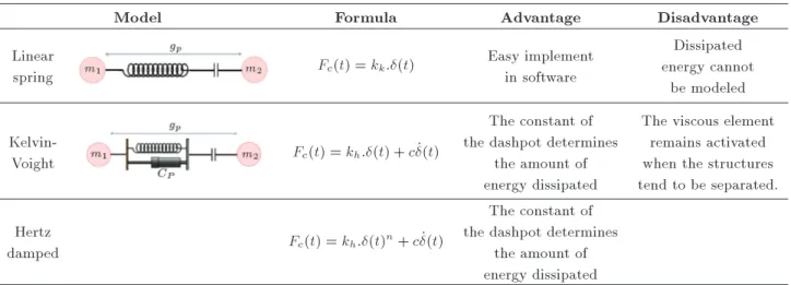
Finally, using Table 1, dierent models of pounding have been represented. The advantages and disadvan-tage of the models are presented.
5. Proposed nonlinear impact model
For getting a reference relation to cover the three mentioned impact damping relations, a new equation of motion is suggested based on three parameters.
cimp= f(k; CR; vimp): (15)
As noted before, it is assumed that the impact damping coecient is a mathematical function, which calculates the energy dissipation by using:
cimp=
k vimp
n(1 CR2)
CRm : (16)
Based on a cyclic process, cimp was calculated and
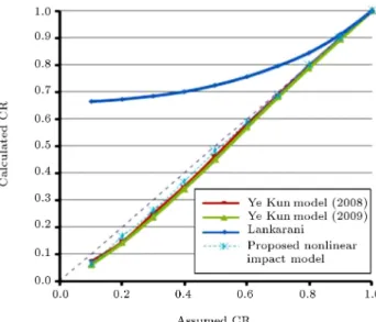
checked to conrm the accuracy of the suggested formula. In this case, a cyclic process has been used to simulate the impact of two assumed bodies. Based on this process and using the coecient of restitution, two parameters were selected. Finally, the represented formula was obtained by selecting n and m. In order to check accuracy and conrm the suggested relation, the energy dissipation was calculated and compared with kinetic energy loss, which is presented in Figure 6.
Consequently, n and m can be selected from Table 2.
For this relation, impact force is represented by: Fimp= 1:5(k + cimp): (17)
By having SDOF masses (m = m1m2
m1+m2), k and vimp,
Table 1. Summary of pounding model.
Model Formula Advantage Disadvantage
Linear
spring Fc(t) = kk:(t)
Easy implement in software
Dissipated energy cannot
be modeled
Kelvin-Voight Fc(t) = kh:(t) + c _(t)
The constant of the dashpot determines
the amount of energy dissipated
The viscous element remains activated when the structures tend to be separated. Hertz
damped Fc(t) = kh:(t)
n+ c _(t)
The constant of the dashpot determines
the amount of energy dissipated Table 2. Three used unknown parameters.
E 0.1 0.2 0.3 0.4 0.5 0.6 0.7 0.8 0.9
N 1.05144 1.04 1.03092 1.022 1.0115 0.9973 0.9775 0.95016 0.9133 M 1.0025 1.0017 1.0005 0.9945 0.9862 0.9754 0.9668 0.9551 0.9512
Figure 6. Comparison of results of four dierent formulas.
After selecting CR, cimp is calculated and the
hysteresis loop is depicted. In order to examine the eects of using dierent impact models, an analytical model has been used to calculate the kinetic energy loss and compare it with other mentioned relations.
For example, the SDOF mass of two bodies is assumed to be 755.76 kN. The impact stiness for the used link element and impact velocity is calculated as 30003.67 and 9.976, respectively. For simplifying the simulation of impact, a suitable estimation of k and vimp is taken to be equal to 30000 and 10, in order to
be used in all formulas for estimation of the impact
damping. The coecient of restitution is also assumed to be 0.7.
5.1. Numerical analyses to investigate the accuracy of formula
To evaluate and conrm the suggested equation, two single degree of freedom systems are assumed. In this evaluation, two bodies are connected with each other by a link element, which is modeled by a spring and damper. Two mentioned elements are located parallel with each other to calculate the impact force and also dissipated energy. The mass of two bodies is assumed to be 100 and 150 ton for buildings A and B, respectively. The stiness of the spring is 22000 and the impact velocity is also estimated to be equal to 15. Coecients of restitution are selected from 0.1 to 0.9. A reference lateral displacement is used and its derivation is calculated to be the velocity of the SDOF systems.
The suggested equation of motion is simulated to get the results of the impact and dissipated energy. By using dierent e, the impact curve is depicted and dissipated energy is calculated due to the hysteretic behavior of impact. In order to investigate the accuracy of the suggested formula, dissipated energy is compared with kinetic energy loss, as presented in Figures 7 and 8. Kinetic energy can be described as [19]:
E = 12mm1m2
1+ m2(1 CR 2)(
imp)2: (18)
In this simulation, assumed coecients of restitution are compared with calculated coecients of restitution. In Table 3, the percentage of error is presented.
Table 3. Error in calculated coecient of restitution.
Assumed CR 0.1 0.2 0.3 0.4 0.5 0.6 0.7 0.8 0.9
Calculated CR 0.065 0.165 0.264 0.372 0.486 0.591 0.695 0.798 0.9 Error 0.35 0.175 0.12 0.07 0.128 0.015 0.002 0 0
Figure 7. Comparison of hysteresis loops by using dierent CR for proposed nonlinear impact force.
Figure 8. Error estimation for proposed nonlinear impact force.
6. Relation between coecient of restitution and impact velocity
From numerical analyses, the coecient of restitution, CR, is calculated. It seems that there is a need to have a reference curve to select vimp based on the
coecient of restitution, which is able to show the optimum results in terms of dissipated energy. To evaluate the impact velocity, it is assumed that the reference velocity is 10 and the value of CR is 0.5. The procedure that has been followed for the derivation of the impact velocity is demonstrated in Figure 9.
Firstly, the value of vimp is selected and the
coecient of restitution is also assumed. After each simulation, the kinetic energy loss is checked as to whether it equals the area of the hysteresis loop
Figure 9. The procedure that has been followed in order to derive the formula that provides optimum CR and vimp.
Figure 10. The comparison of two dierent properties.
obtained from the analysis, and, if not, the constant CR is modied and a new analysis is performed (Figure 10). For instance, analyses have shown that the dissi-pated energy of the hysteresis loop, using vimp= 11 and
CR=0.45 and the reference model, are approximately equal. Kinetic energy losses are 28.33261 and 28.64157 in the reference and second models, respectively.
men-Figure 11. Suggested curve for CR and vimp.
tioned method in the chart, the following formula has been obtained relating the coecient of restitution. The estimated formula can be written by:
vimp=494:32CR4 1299CR3+ 1285CR2
595:9CR + 116:67: (19) It can be seen from Figure 11 that Eq. (19) simulates quite precisely the relation between the coecient of restitution and impact velocity. It is worth mentioning that the decreased trend in the impact velocity for increasing the value of the coecient of restitution has been conrmed by Jankowsky [15].
7. Relation between coecient of restitution and impact damping ratio ()
As noted in Eq. (19), the loss in kinetic energy depends on mass, coecient of restitution and impact velocity. The steady state response of the single degree of freedom system, due to the external force, p(t) = p0sin(wt), has been evaluated. Based on the mentioned
force, the dissipated energy due to the viscose damper in harmonic excitation can be written by the following the relation:
E = Z
fDd =
Z 2=w
0 (ck_) _dt: (20)
Also, by focusing strongly on the damping term of equation of motion the following is obtained:
E = Z max
0 ck_d: (21)
Based on the equations of dynamics of structures [20]: E = 2ww
nk
2; (22)
in which, w is radial frequency and wnis damped radial
frequency. The relation between w and wn could be
assumed to be 1. Considering nal velocity and mass, it could be written as:
Z
fDd =
Z 2=w
o (ck_) _dt = 0:5m _ 2
nal; (23)
where _nal denotes the nal velocity and m is an
equivalent of two masses (m = m1m2
m1+m2). In order to
solve Eq. (23) for , the following equation is used:
max=
r m
4k: _nal: (24) For each value of deformation during impact, as the energy transfers from elastic strain energy to kinetic energy, the relative velocity can be calculated as follows:
2k2+ 0:5m _2= 0:5m _2
nal: (25)
Solving Eq. (25), the following relation is obtained: 0:5m _2= 0:5m _2
nal 2k2: (26)
Consequently, velocity would be: _
r _2
nal 4k 2
m : (27)
Dening Relation (4) and considering the displacement of zero ( = 0), it is an assumption that Eq. (27) can be changed by using the coecient of restitution to determine the velocity during collision for _ > 0 and
_ < 0. _ =
r _2
nal 4k 2
m for _ < 0
_ = 1CR r
_2
nal 4k 2
m for _ > 0: (28) Using the dissipated energy from the damper and referring to Eq. (20), it could be calculated by:
E = 2pk:m Z
_d: (29)
Considering the above relations and submitting Eq. (28) into Eq. (29), the following is obtained:
E = 2CR pk:m Z r
_2
nal 4k 2
m d: (30) by substituting Eq. (23) into Eq. (30):
E = 2CR pk:m Z max
0
r 4k2
max
m
4k2
m d:(31) The relation is simplied to Eq. (31):
E = 2CR pk:m r
4k m
! Z max
0
p 2
max 2d;
E = 4kCR1:5p Z max
0
p 2
max 2d: (33)
Solving Eq. (33), it can be represented that the dissi-pated energy will be:
E = 4kCR1:5p(0:252
max): (34)
Kinetic energy loss, noted in Eq. (31), can be equal to the dissipated energy from the damper during impact, as:
1 2
m1m2
m1+m2(1 CR 2)(
imp)2=4k 1:5
CR p
(0:252 max):
(35) Modifying 2
max from Eq. (23) into Eq. (35), the
following would be obtained: 1
2
m1m2
m1+ m2(1 CR 2)(
imp)2
= 4k1:5 CR
p
0:25_2nal
4k
m1m2
m1+ m2
!
: (36)
Eq. (36) could be written as:
(1 cr2)( imp)2=
p :
2:CR( _nal2 ): (37)
And, nally, the relation for giving will be:
=
2
CR:p(1 CR2) 2
: (38)
Considering three dierent , calculated from past studies, a numerical analysis was carried out to com-pare three impact damping ratios. In order to inves-tigate the calculated , a single degree of freedom is simulated to evaluate the impact force between two masses. Three used dierent impact damping ratios from Jankowski [15], Seyed Mahmoud [21] and the mentioned equation of motion, are seen in Table 4.
The results of a comparison between impact damping ratios, based on the coecient of restitution, are shown in Figure 12. The impact damping ratio is started from 61, 3.5 and 3.2 for the proposed model, Jankowski's model, and Seyed Mahmoud's model, re-spectively. The results tend to zero for all investigated models. It seems that the suggested equation of motion
Table 4. Utilized impact damping ratios. Jankowski's equation p5
21 CR
2
CR
Seyed Mahmoud's equation 1 1 CR
2
CR
Proposed equation = 2
CR:p(1 CR2)
2
Figure 12. Comparison among dierent formulations by using dierent values for CR.
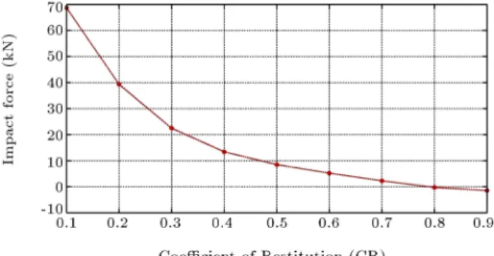
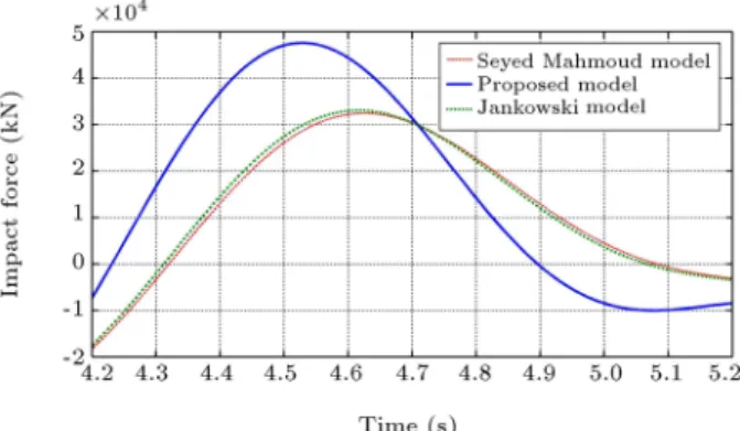
Figure 13. Comparison of impact forces among three dierent types of impact damping ratios.
Figure 14. Comparison of impact forces among three coecients of restitution.
in this paper can show an acceptable curve between the two other formulas. The curve of this model makes it sensible to get the impact damping ratio based on the coecient of restitution, as the results are close to each other, from CR=0.4 to CR=0.9 (Figure 13). To better express this, selecting dierent coecients of restitution from 0.4 to 0.9 will have similar responses, in terms of impact damping ratio and impact forces (Figure 14).
8. Conclusion
In this paper, building pounding during seismic exci-tation has been investigated. Firstly, the concept of
impact between two masses has been described to get a better image of collisions during an earthquake. Two dierent types of link element have been explained. The rst has a spring and the second has a spring and damper, which are located parallel to each other. Shown in Table 1, the advantages and disadvantages of link elements have been investigated. The majority of equations of motion in terms of impact force have been collected, and impact damping in terms of these relations has been demonstrated. A new relation to calculate the value of damping has been suggested to get the best results in terms of dissipated energy. To evaluate the accuracy of the suggested formula, the relationship between the selected coecient of restitution and the calculated coecient of restitution has been plotted in a curve. The results show good accuracy in comparison with other formulas.
As there is a need to have a reference curve to select vimp based on the coecient of restitution, a
cyclic process was simulated to suggest the optimum relation between impact velocity and coecient of restitution. To reach this goal, the impact velocity and coecient of restitution were assumed to be references. Based on this assumption, another impact velocity and coecient of restitution is estimated and its hysteresis loop is depicted. Dissipated energy is calculated and compared with the energy principle. If both are equal, the assumed velocity and coecient of restitution are conrmed. If not, the process is repeated to get the best selection. Finally, a relation between the two investigated parameters was represented to predict im-pact velocity. Considering the coecient of restitution, impact velocity is calculated to have a similar response using dierent impacts and coecients of restitution.
A new relation between coecient of restitution and impact damping ratio has been presented to evaluate linear and nonlinear impact models. Using mathematical relations and considering the steady state response of single degree of freedom systems due to external force, based on harmonic force, a new relation was suggested and compared with other sug-gested formulas. The calculated impact damping ratio depends signicantly on the coecient of restitution and shows better results in comparison with other relations.
References
1. Yaghmaei-Sabegh, S. and Jalali-Milani, N. \Pounding force response spectrum for near-eld and far-eld earthquakes", Scientia Iranica, 19(5), pp. 1236-1250 (2012).
2. Anagnostopouls, S.A. \Pounding of building in se-ries during earthquakes", Earthquake Engineering and Structural Dynamics, 16(3), pp. 443-456 (1998).
3. Papadrakakis, M. and Mouzakis, H. \A Lagrange
mul-tiplier solution method for pounding of building during earthquakes", Journal of Earthquake Engineering and Structural Dynamics, 20, pp. 981-998 (1991).
4. Filiatrault, A. and Wagner, P. \Analytical prediction of experimental building pounding", Journal of Earth-quake Engineering and Structural Dynamics, 24, pp. 1131-1154 (1995).
5. Kavashima, C.G. and Watanaba, K. \Earthquake induced interaction between adjacent reinforced con-crete structural with non-equal heights", Earthquake Engineering and Structural Dynamics, 34(1), pp. 1-20 (2005).
6. Cole, G.L. and Dhakal, R.P. \The eect of diaphragm wave propagation on the analysis of pounding struc-tures", Proc. 2nd Int. Conference on Computational Method in Structural Dynamic an Earthquake Engi-neering (COMPADYN), Greece (2009).
7. Barros, R. and Khatami, S.M. \Importance of sepa-ration distance on building pounding under near-fault ground motion, using the Iranian earthquake code", 9th International Congress on Civil Engineering, Is-fahan University of Technology (IUT), IsIs-fahan, Iran (2012).
8. Komodromos, P. and Polycarpou, P. \On the nu-merical simulation of impact for the investigation of earthquake-induced pounding of building", Tenth International Conference on Computational Structures Technology, Civil-Comp Press, Stirlingshire, Scotland (2010).
9. Vasconcelos, H. \Study about collision between rein-forced concrete building and comparison of their re-sistance envelope by push over analysis", MSc Thesis, FEUP, Portugal (2011).
10. Raj, P. and Wijeyewickrema, C., Seismic Pounding Between Reinforced Concrete Buildings: A Study Us-ing two recently proposed Contact Element Models, 14ECEE, Ohrid, Macedonia (2010).
11. Cordeiro, J.M.C. \Study of the collision between build-ings without and with base isolation", MSc Thesis in Civil Engineering, Porto, Portugal (2011).
12. Vasconcelos, H.E. \Study of the collision between reinforced concrete buildings and comparison of their pushover capacities", MSc Thesis in Civil Engineering, Porto, Portugal (2011).
13. Barros, R.C. and Khatami, S.M. \An estimation of damping ratio for the numerical study of impact forces between two adjacent concrete buildings, subjected to pounding", 15th International Conference on Ex-perimental Mechanics (15th ICEM), Symposium on \Dynamics and Stability", FEUP, pp. 22-27, Porto, Portugal (July 2012).
14. Barros, R.C. and Khatami, S.M. \Building pounding forces for dierent link element models", Proceedings of the Eleventh International Conference on Computa-tional Structures Technology, Dubrovnik, Croatia, pp. 4-7 (September 2012).
15. Jankowski, R. \Non-linear viscoelastic modeling of earthquake-induced structural pounding", Earthquake Engineering and Structural Dynamics, 34, pp. 595-611 (2005).
16. Ye, K. and Zhu, H. \A note on the Hertz contact model with nonlinear damping for pounding simulation", Earthquake Engineering and Structural Dynamics., 38(9), pp. 1135-1142 (2008).
17. Lankarani, S. \A Hertz contact model with non-linear damping for pounding simulation", Earthquake Engineering and Structural Dynamics., 35, pp. 811-828 (2006).
18. Ye, K. and Zhu, H. \A modied Kelvin impact model for pounding simulation of base-isolated building with adjacent structure", Earthquake Engineering and En-gineering Vibration, 8, pp. 433-446 (2009).
19. Goldsmith, W. \Impact: The theory and physical behavior of colliding solids", Edward Arnold: London, U.K. (1960).
20. Chopra, A.K., Dynamics of Structures, Theory and Applications to Earthquake Engineering, University of California at Berkeley (1995).
21. Mahmoud, S. and Jankowski, R. \Modied linear viscoelastic model of earthquake induced structural pounding", Iranian Journal of Science & Technology, 35(C1), pp. 51-62 (2011).
Biographies
Hosein Naderpour was born in 1981 in Tehran, Iran. He obtained his BSc, MSc and PhD degrees in Civil and Structural Engineering in 2003, 2006 and 2010, respectively. He then joined Semnan University where he is presently assistant professor of Structural Engineering. He is also the director of research aairs in Semnan University. Dr. Naderpour is author of 30 papers published in journals and 70 papers presented at national and international conferences. He has given several speeches in Switzerland, China, Australia, Canada, Belgium, Portugal, Spain, Germany, Italy and France. His research interests include: articial
intelligence, composite structures, structural reliabil-ity, structural optimization, design and construction of externally bonded FRP systems for strengthening concrete structures and base isolation systems. Rui Manuel de Menezes e Carneiro de Barros was graduated in Civil Engineering from Faculty of En-gineering University of Porto (FEUP), Portugal (l974). He received his MSc degree in Ocean Engineering at the University College, London, England (l976), and his PhD degree in Civil Engineering at the University of Akron, Ohio, USA (1983). Since 1983, he has been a Professor in the Civil Engineering Department of the University of Porto (FEUP). He is the author of more than 220 published scientic papers (70than 90 inter-nal technical reports, and numerous handwritten and printed course-notes for undergraduate and graduate use. Presently, he is the FEUP university scientic coordinator of an industrial collaborative project with the Metalogalva (Project VHSS-Poles for duration of 3 years, and a total budget of around 1 million euro), for addressing the construction and certication of an experimental station on an industrial plant at northern Portugal. Besides, he had 11 invited speeches in Portugal, has given 25 invited speeches in Chile, Brazil, Thailand, China, Singapore, Lithuania, Italy, Ireland, Malta and Denmark. During May 2005 and also during July 2010, he has been `Exchange Professor', respec-tively, at Kaunas Technical University and Vilnius Gediminas Technical University, both in Lithuania, under an Erasmus Mobility Grant for Professors. Seyed Mohammad Khatami was born in 1982 in Semnan, Iran. He obtained his BS and MS degrees in Structural Engineering in 2007 and 2010, respec-tively. His research interests include: dynamics of structures, building pounding, and nonlinear analysis of RC structures. He is presently a PhD student in Semnan University. Mr. Khatami is author of 5 papers published in journals and 30 papers presented at national and international conferences.