Intel® Desktop Board DP67BG
Product Guide
Revision History
Revision Revision History Date
-001 First release of the Intel® Desktop Board DP67BG Product Guide November 2010
Disclaimer
INFORMATION IN THIS DOCUMENT IS PROVIDED IN CONNECTION WITH INTEL® PRODUCTS. NO LICENSE, EXPRESS OR IMPLIED, BY ESTOPPEL OR OTHERWISE, TO ANY INTELLECTUAL PROPERTY RIGHTS IS GRANTED BY THIS DOCUMENT. EXCEPT AS PROVIDED IN INTEL’S TERMS AND CONDITIONS OF SALE FOR SUCH PRODUCTS, INTEL ASSUMES NO LIABILITY WHATSOEVER, AND INTEL DISCLAIMS ANY EXPRESS OR IMPLIED WARRANTY, RELATING TO SALE AND/OR USE OF INTEL PRODUCTS INCLUDING LIABILITY OR WARRANTIES RELATING TO FITNESS FOR A PARTICULAR PURPOSE, MERCHANTABILITY, OR INFRINGEMENT OF ANY PATENT, COPYRIGHT OR OTHER INTELLECTUAL PROPERTY RIGHT. Intel products are not intended for use in medical, life saving, or life sustaining applications. Intel may make changes to specifications and product descriptions at any time, without notice.
Intel Desktop Board DP67BG may contain design defects or errors known as errata which may cause the product to deviate from published specifications. Current characterized errata are available on request. Contact your local Intel sales office or your distributor to obtain the latest specifications and before placing your product order.
Copies of documents which have an ordering number and are referenced in this document, or other Intel literature, may be obtained from Intel Corporation by going to the World Wide Web site at:
http://www.intel.com/ or by calling 1-800-548-4725.
Intel, Intel Core, and Xeon are trademarks of Intel Corporation in the United States and other countries. * Other names and brands may be claimed as the property of others.
iii
Preface
This Product Guide gives information about board layout, component installation, BIOS update, and regulatory requirements for Intel® Desktop Board DP67BG.
Intended Audience
The Product Guide is intended for technically qualified personnel. It is not intended for general audiences.
Use Only for Intended Applications
All Intel Desktop Boards are evaluated as Information Technology Equipment (I.T.E.) for use in personal computers (PC) for installation in homes, offices, schools, computer rooms, and similar locations. The suitability of this product for other PC or embedded non-PC applications or other environments, such as medical, industrial, alarm systems, test equipment, etc. may not be supported without further evaluation by Intel.
Document Organization
The chapters in this Product Guide are arranged as follows: 1 Desktop Board Features: a summary of product features
2 Installing and Replacing Desktop Board Components: instructions on how to install the Desktop Board and other hardware components
3 Updating the BIOS: instructions on how to update the BIOS
4 Configuring for RAID Using Intel® Rapid Storage Technology: information about configuring your system for RAID
A Error Messages and Indicators: information about BIOS error messages and beep codes
B Regulatory Compliance: describes the board’s adherence to safety standards and EMC regulations and its product certifications
Conventions
The following conventions are used in this manual:
CAUTION
Cautions warn the user about how to prevent damage to hardware or loss of data. NOTE
Terminology
The table below gives descriptions of some common terms used in the product guide.
Term Description
GB Gigabyte (1,073,741,824 bytes) GHz Gigahertz (one billion hertz)
KB Kilobyte (1024 bytes) MB Megabyte (1,048,576 bytes)
Mb Megabit (1,048,576 bits)
v
Contents
1
Desktop Board Features
Supported Operating Systems...11
Desktop Board Components...12
Processor...14
Main Memory...15
Intel® P67 Express Chipset ...16
Audio Subsystem ...16
LAN Subsystem ...17
USB Support ...18
Serial ATA Support ...18
Legacy I/O ...18
Expandability...18
BIOS ...19
Serial ATA Auto Configuration...19
PCI* and PCI Express* Auto Configuration ...19
Security Passwords ...19
Back to BIOS Button ...20
Hardware Management ...20
Hardware Monitoring and Fan Speed Control ...20
Chassis Intrusion...21 Power Management ...21 Software Support ...21 ACPI...21 Hardware Support ...21 Power Connectors ...21 Fan Headers ...22
LAN Wake Capabilities...22
Instantly Available PC Technology...22
Wake from USB ...23
PME# Signal Wake-up Support...23
WAKE# Signal Wake-up Support ...23
Wake from Consumer IR ...23
Onboard Power and Reset Buttons...24
Processor and Voltage Regulator LEDs ...25
Diagnostic LEDs ...26
Speaker...27
Battery...27
Real-Time Clock...27
2
Installing and Replacing Desktop Board Components
Before You Begin ...29Installation Precautions...30
Prevent Power Supply Overload ...30
Observe Safety and Regulatory Requirements...30
Installing the I/O Shield ...31
Installing and Removing the Desktop Board ...32
Installing a Processor ...33
Installing the Processor Fan Heat Sink ...37
Connecting the Processor Fan Heat Sink Cable...37
Removing the Processor ...37
Installing and Removing System Memory ...38
Guidelines for Dual Channel Memory Configuration...38
Two or Four DIMMs ...38
Three DIMMs ...39
Installing DIMMs ...40
Removing DIMMs...42
Installing and Removing PCI Express x16 Graphics Cards...42
Installing a PCI Express x16 Graphics Card ...42
Removing a PCI Express x16 Graphics Card...44
Installing Linked PCI Express Graphics Cards...44
Connecting the Serial ATA (SATA) Cables ...46
Connecting to the Internal Headers ...47
S/PDIF Header ...48
IEEE 1394a Header...48
Front Panel Intel HD Audio Header ...48
Alternate Front Panel Power LED Header ...49
Consumer IR (CIR) Headers ...49
USB 2.0 Headers ...50
Front Panel Header ...51
Chassis Intrusion Header ...51
Connecting to the Audio System...52
Connecting Chassis Fan and Power Supply Cables...53
Connecting Chassis Fan Cables ...53
Connecting Power Supply Cables ...54
Setting the BIOS Configuration Jumper ...55
Clearing Passwords ...56
Replacing the Battery ...57
Installing the WiFi/Bluetooth* Module in a Desktop Chassis...63
3
Updating the BIOS
Updating the BIOS with the Intel® Express BIOS Update Utility...65Updating the BIOS Using the F7 Function Key ...66
Updating the BIOS with the Intel® Flash Memory Update Utility or the ISO Image BIOS Update File ...66
Obtaining the BIOS Update File ...66
Updating the BIOS with the Intel Flash Memory Update Utility...67
Updating the BIOS with the ISO Image BIOS Update File ...67
vii
A
Error Messages and Indicators
BIOS Error Codes...71
BIOS Error Messages ...72
Port 80h POST Codes...73
B
Regulatory Compliance
Safety Standards ...77Battery Caution ...77
European Union Declaration of Conformity Statement...78
Product Ecology Statements ...79
Recycling Considerations ...79
China RoHS ...82
EMC Regulations ...83
FCC Declaration of Conformity...83
Canadian Department of Communications Compliance Statement ...84
Japan VCCI Statement ...84
Korea Class B Statement ...85
Ensure Electromagnetic Compatibility (EMC) Compliance ...85
Product Certifications...86
Board-Level Certifications ...86
Chassis- and Component-Level Certifications ...87
Chassis and Component Certifications...87
ENERGY STAR*, e-Standby, and ErP Compliance ...88
Figures
1. Intel Desktop Board DP67BG Components...122. LAN Connector LEDs ...17
3. Location of the Back to BIOS Button...20
4. Onboard Power and Reset Buttons ...24
5. Location of the Processor and Voltage Regulator LEDs...25
6. Location of the Diagnostic LEDs ...27
7. Installing the I/O Shield ...31
8. Intel Desktop Board DP67BG Mounting Screw Hole Locations ...32
9. Unlatch the Socket Lever ...33
10. Lift the Load Plate...34
11. Remove the Processor from the Protective Cover ...35
12. Install the Processor ...35
13. Secure the Load Plate in Place ...36
14. Connecting the Processor Fan Heat Sink Power Cable to the Processor Fan Header...37
15. Example Dual Channel Memory Configuration with Two DIMMs ...38
16. Example Dual Channel Memory Configuration with Four DIMMs ...39
17. Example Dual Channel Memory Configuration with Three DIMMs ...39
18. Use DDR3 DIMMs ...40
19. Installing a DIMM ...41
20. Installing a PCI Express x16 Graphics Card ...43
21. Removing a PCI Express x16 Graphics Card...44
22. Installing Linked PCI Express Graphics Cards...45
23. Connecting the Serial ATA Cables...46
25. Back Panel Audio Connectors ...52
26. Location of the Chassis Fan Headers...53
27. Connecting Power Supply Cables ...54
28. Location of the BIOS Configuration Jumper Block ...55
29. Removing the Battery ...62
30. Installing the WiFi/Bluetooth Module ...64
31. POST Code LED Display ...73
32. Intel Desktop Board DP67BG China RoHS Material Self Declaration Table...82
Tables
1. Feature Summary... 92. Intel Desktop Board DP67BG Components...13
3. Audio Jack Retasking Support...16
4. LAN Connector LEDs ...17
5. Diagnostic LEDs ...26
6. S/PDIF Header Signal Names ...48
7. IEEE 1394a Header Signal Names ...48
8. Front Panel Intel HD Audio Header Signal Names ...48
9. Alternate Front Panel Power LED Header Signal Names ...49
10.Front Panel CIR Receiver (Input) Header Signal Names ...49
11.Back Panel CIR Header Emitter (Output) Header Signal Names ...50
12.USB 2.0 Header Signal Names...50
13.Front Panel Header Signal Names ...51
14.Chassis Intrusion Header Signal Names ...51
15.Jumper Settings for the BIOS Setup Program Modes...56
16.BIOS Beep Codes ...71
17.Front-panel Power LED Blink Codes ...71
18.BIOS Error Messages ...72
19.Port 80h POST Codes ...73
20.Safety Standards...77
21.EMC Regulations...83
9
1 Desktop Board Features
This chapter briefly describes the features of Intel® Desktop Board DP67BG. Table 1 summarizes the major features of the Desktop Board.
Table 1. Feature Summary
Form Factor ATX (304.80 millimeters [12.00 inches] x 243.84 millimeters [9.60 inches])
Processor Support for an Intel® processor in the LGA1155 package
Main Memory • Four 240-pin DDR3 SDRAM Dual Inline Memory Module (DIMM) sockets arranged in two channels
• Support for DDR3 2400 MHz to DDR3 1066 MHz DIMMs • Support for 1.35 V memory
• Support for non-ECC memory • Support for up to 32 GB of memory
Chipset Intel® P67 Express Chipset consisting of the Intel P67 Platform
Controller Hub (PCH)
Graphics Support for multiple PCI Express* 2.0 graphics cards
Audio • Independent multi-streaming 8-channel (7.1) audio and 2-channel audio subsystem, featuring:
― Intel® High Definition (Intel® HD) Audio interface ― Realtek* ALC892 codec
• HD Audio front panel header • Onboard 4-pin S/PDIF out header
• Back panel S/PDIF out optical connector (TOSLINK)
Expansion
Capabilities •
One PCI Express 2.0 x16 port
• One PCI Express 2.0 x8 port (x8 electrical; 16 compatible) • Three PCI Express 2.0 x1 ports
• Two PCI* bus connectors
Legacy I/O Support Nuvoton W83677HG-I legacy I/O controller that provides Consumer Infrared (CIR) support
Peripheral Interfaces
USB Support:
• Two USB 3.0 ports implemented with stacked back panel connectors (blue)
• Fourteen USB 2.0 ports:
― Eight ports implemented with stacked back panel connectors
― Six front panel ports implemented with three dual-port internal headers
Serial ATA Support:
• Two Serial ATA (SATA) 6.0 Gb/s ports (blue) • Four Serial ATA (SATA) 3.0 Gb/s ports
• One external SATA (eSATA) 3.0 Gb/s port on the back panel IEEE 1394a Support:
• One port routed to the back panel • One port routed to an IEEE 1394a header
RAID Intel® Rapid Storage Technology (Intel® RST)
LAN Support Intel 82579V Gigabit (10/100/1000 Mb/s) Ethernet LAN controller including an RJ-45 back panel connector with integrated status LEDs
BIOS • Intel® Platform Innovation Framework for extensible firmware
interface
• 32 Mb symmetrical flash memory device • Support for SMBIOS
• Intel® Express BIOS Update
Power Management • Support for Advanced Configuration and Power Interface (ACPI) • Suspend to RAM (STR)
• Wake on USB, PCI, PCI Express, LAN, CIR, and front panel • ENERGY STAR* capable
Hardware and Thermal Management
Hardware and thermal management based on:
― Nuvoton W83677HG-I legacy I/O controller
― Four fan sensing inputs to monitor fan activity
11
Supported Operating Systems
The Desktop Board provides full support for the following operating systems:
• Microsoft Windows* 7 Ultimate 64-bit edition
• Microsoft Windows 7 Ultimate 32-bit edition
• Microsoft Windows 7 Professional 64-bit edition
• Microsoft Windows 7 Professional 32-bit edition
• Microsoft Windows 7 Home Premium 64-bit edition
• Microsoft Windows 7 Home Premium 32-bit edition
• Microsoft Windows 7 Starter 64-bit edition
• Microsoft Windows 7 Starter 32-bit edition
• Microsoft Windows Vista* Ultimate 32-bit edition
• Microsoft Windows Vista Business 32-bit edition
• Microsoft Windows Vista Home Premium 32-bit edition
• Microsoft Windows Vista Home Basic 32-bit edition
• Microsoft Windows Vista Ultimate 64-bit edition
• Microsoft Windows Vista Business 64-bit edition
• Microsoft Windows Vista Home Premium 64-bit edition
• Microsoft Windows Vista Home Basic 64-bit edition
The Desktop Board provides limited support for the following operating systems:
• Microsoft Windows Vista Home Basic 64-bit edition
• Microsoft Windows* XP Media Center Edition 2005
• Microsoft Windows XP Professional
• Microsoft Windows XP Professional x64 Edition
Desktop Board Components
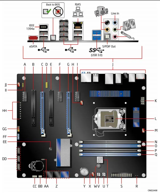
Figure 1 shows the approximate location of the major components on Intel Desktop Board DP67BG.
13
Table 2. Intel Desktop Board DP67BG Components
Label Description
A PCI Express 2.0 x1 connector B PCI bus connector
C PCI Express 2.0 x16 connector (x8 electrical; x16 compatible) D Front panel audio header
E PCI bus connector
F PCI Express 2.0 x1 connector G PCI Express 2.0 x16 connector H Rear chassis fan header I PCI Express 2.0 x1 connector J Back panel connectors
K 12 V processor core voltage connector (2 x 4 pin) L Processor socket
M Processor fan header N DIMM 3 socket O DIMM 1 socket P DIMM 4 socket Q DIMM 2 socket
R Alternate front panel power LED header S Main power connector (2 x 12 pin) T POST code LED display
U Onboard reset button V Onboard power button W Speaker
X Front chassis fan header Y Battery
Z Serial ATA (SATA) connectors AA BIOS configuration jumper block
BB Back panel CIR transmitter (output) header CC Front panel CIR receiver (input) header DD USB 2.0 headers
EE Chassis intrusion header FF IEEE 1394a header
GG Front panel header HH Diagnostic LEDs
II S/PDIF header
Online Support
For more information on Intel Desktop Board DP67BG consult the following online resources:
• Intel Desktop Board DP67BG
• Desktop Board Support
• Available configurations for Intel Desktop Board DP67BG
• Supported processors
• Chipset information
• BIOS and driver updates
• Integration information
Processor
CAUTIONFailure to use an appropriate power supply and/or not connecting the 12 V (2 x 4 pin) power connector to the Desktop Board may result in damage to the board, or the system may not function properly.
Intel Desktop Board DP67BG supports an Intel processor in the LGA1155 package. Processors are not included with the Desktop Board and must be purchased
separately. The processor connects to the Desktop Board through the LGA1155 socket.
For information on supported processors for Intel Desktop Board DP67BG, go to
15
Main Memory
NOTETo be fully compliant with all applicable Intel® SDRAM memory specifications, the
board should be populated with DIMMs that support the Serial Presence Detect (SPD) data structure. If your memory modules do not support SPD, you will see a
notification to this effect on the screen at power up. The BIOS will attempt to configure the memory controller for normal operation.
The Desktop Board supports the following memory and interface:
• Four 240-pin Double Data Rate 3 (DDR3) SDRAM Dual Inline Memory Module (DIMM) sockets with gold-plated contacts arranged in two channels
• 2133 MHz to 1066 MHz DDR3 SDRAM Memory Modules
• Support for single- and dual-channel memory interleaving
• Unbuffered, non-registered single- or double-sided DIMMs with a voltage rating of 1.65 V or less
NOTE
Using a DIMM with a voltage rating higher than 1.65 V may damage the processor.
• Non-ECC DDR3 memory
• Serial Presence Detect (SPD) memory only
• Up to 32 GB maximum total system memory using 8 GB DIMMs
NOTE
32-bit operating systems are limited to a maximum of 4 GB of memory. These operating systems will report less than 4 GB because of the memory used by add-in graphics cards and other system resources.
Intel
®
P67 Express Chipset
The Intel P67 Express Chipset consists of the Intel P67 Platform Controller Hub (PCH). The PCH is the centralized controller for the board’s I/O paths.
Audio Subsystem
The onboard audio subsystem consists of the following components:
• Intel® P67 PCH
• Realtek ALC892 codec
The subsystem has the following headers and connectors:
• Back panel audio connectors, including an S/PDIF out optical port.
• Advanced jack sense for the back panel audio connectors that enables the audio codec to recognize the device that is connected to an audio port
• High Definition Audio Front panel audio header that supports Intel HD Audio and AC ‘97 Audio. This header provides mic in and line out signals for front panel audio connectors.
• An onboard S/PDIF header
The audio subsystem supports the following features:
• A signal-to-noise (S/N) ratio of 97 dB
• Independent multi-streaming 8-channel (7.1) audio (using the back panel audio connectors) and 2-channel audio (using the High Definition Audio front panel header)
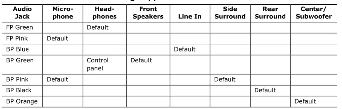
Table 3 lists the supported functions of front panel and back panel audio jacks.
Table 3. Audio Jack Retasking Support
Audio
Jack Micro- phone phones Head- Speakers Front Line In Surround Side Surround Rear Subwoofer Center/
FP Green Default FP Pink Default BP Blue Default BP Green Control panel Default
17
LAN Subsystem
The LAN subsystem includes:
• Intel P67 PCH
• Intel 82579V Gigabit (10/100/1000 Mb/s) Ethernet LAN controller
• RJ-45 LAN connector with integrated status LEDs The subsystem features:
• CSMA/CD protocol engine
• LAN connect interface between PCH and the LAN controller
• PCI bus power management
Two LEDs are built into the RJ-45 LAN connector located on the back panel (see Figure 2). These LEDs indicate the status of the LAN as shown in Table 4.
Figure 2. LAN Connector LEDs Table 4. LAN Connector LEDs
LED LED Color LED State Indicates
A Green Off LAN link is not established
On LAN link is established
Blinking LAN activity is occurring
N/A Off 10 Mb/s data rate
Green On 100 Mb/s data rate
B
USB Support
The Desktop Board supports USB 2.0 and USB 3.0. There are 14 USB 2.0 ports (eight ports routed to back panel connectors and six ports routed to three onboard headers). The USB 2.0 ports are high-speed, full-speed, and low-speed capable.
USB 3.0 is supported by two back panel connectors (blue). USB 3.0 ports are backward compatible with USB 2.0 and USB 1.1 devices. The USB 3.0 ports are SuperSpeed, high-speed, full-speed, and low-speed capable.
Serial ATA Support
Intel Desktop Board DP67BG supports two onboard 6.0 Gb/s Serial ATA (SATA) channels and four onboard 3.0 Gb/s SATA channels. The board also provides one 3.0 Gb/s external SATA (eSATA) channel via a back panel connector.
The onboard SATA channels provided by the PCH support Intel Rapid Storage Technology which provides the following RAID (Redundant Array of Independent Drives) levels:
• RAID 0 - data striping
• RAID 1 - data mirroring
• RAID 0+1 (or RAID 10) - data striping and data mirroring
• RAID 5 - distributed parity
Legacy I/O
Intel Desktop Board DP67BG includes a legacy I/O controller that provides the following I/O features:
• Consumer Infrared (CIR) support
• Low pin count (LPC) interface
• Intelligent power management, including a programmable wake up event interface
• PCI power management support
Expandability
19
BIOS
The BIOS provides the Power-On Self-Test (POST), the BIOS Setup program, and the PCI/PCI Express and SATA auto-configuration utilities. The BIOS is stored in the Serial Peripheral Interface (SPI) Flash device.
The BIOS can be updated by following the instructions in Chapter 3 starting on page 65.
Serial ATA Auto Configuration
If you install a Serial ATA device (such as a hard drive) in your computer, the auto-configuration utility in the BIOS automatically detects and configures the device for your computer. You do not need to run the BIOS Setup program after installing a Serial ATA. You can override the auto-configuration options by specifying manual configuration in the BIOS Setup program.
PCI* and PCI Express
*
Auto Configuration
If you install a PCI/PCI Express add-in card in your computer, the PCI/PCI Express auto-configuration utility in the BIOS automatically detects and configures the
resources (IRQs, DMA channels, and I/O space) for that add-in card. You do not need to run the BIOS Setup program after you install a PCI/PCI Express add-in card.
Security Passwords
The BIOS includes security features that restrict whether the BIOS Setup program can be accessed and who can boot the computer. A supervisor password and a user password can be set for the BIOS Setup and for booting the computer, with the following restrictions:
• The supervisor password gives unrestricted access to view and change all Setup options. If only the supervisor password is set, pressing <Enter> at the password prompt of Setup gives the user restricted access to Setup.
• If both the supervisor and user passwords are set, you must enter either the
supervisor password or the user password to access Setup. Setup options are then available for viewing and changing depending on whether the supervisor or user password was entered.
• Setting a user password restricts who can boot the computer. The password prompt is displayed before the computer is booted. If only the supervisor password is set, the computer boots without asking for a password. If both passwords are set, you can enter either password to boot the computer. Related Links:
Back to BIOS Button
The back panel Back to BIOS button (Figure 3, A) duplicates the functionality of the BIOS configuration jumper (see Setting the BIOS Configuration Jumper on page 55) with the following exceptions:
• It can only be used to force the board to power on to the BIOS Maintenance Menu using default values but it will retain all previously saved changes.
• It cannot be used to override passwords set in the BIOS.
• It cannot be used to invoke BIOS recovery mode. The button glows red when it is activated.
NOTE
Using the Back to BIOS button does not set the board to the factory BIOS defaults. To restore settings to the factory defaults, use the <F9> key once BIOS setup mode is active.
Figure 3. Location of the Back to BIOS Button
Hardware Management
The hardware management features of Intel Desktop Board DP67BG enable the board to be compatible with the Wired for Management (WfM) specification. The board has several hardware management features including the following:
• Fan speed monitoring and control
• Thermal and voltage monitoring
• Chassis intrusion detection
21
• A thermal sensor in the processor
• Thermally monitored closed-loop fan control, for all onboard fans, that can adjust fan speed
Chassis Intrusion
The board supports a chassis security feature that detects if the chassis cover has been removed. The security feature uses a mechanical switch on the chassis that can be connected to the chassis intrusion header on the Desktop Board. See Figure 24 for the location of the chassis intrusion header.
Power Management
Power management is implemented at several levels, including software support through the Advanced Configuration and Power Interface (ACPI) and the following hardware support:
• Power connectors
• Fan headers
• LAN wake capabilities
• Instantly Available PC technology (Suspend to RAM)
• Wake from USB
• Power Management Event signal (PME#) wakeup support
• WAKE# signal wake-up support
• Wake from Consumer IR
Software Support
ACPI
ACPI gives the operating system direct control over the power management and Plug and Play functions of a computer. The use of ACPI with the Desktop Board requires an operating system that provides full ACPI support.
Hardware Support
Power Connectors
ATX12V-compliant power supplies can turn off the computer power through system control. When an ACPI-enabled computer receives the correct command, the power supply removes all non-standby voltages.
When resuming from an AC power failure, the computer returns to the power state it was in before power was interrupted (either on or off). The computer’s response can be set by using the Last Power State feature in the BIOS Setup program’s Boot menu. The Desktop Board has three power connectors. See Figure 27 on page 54 for the location of the power connectors.
Fan Headers
The function/operation of the fans is as follows:
• The fans are on when the computer is in the ACPI S0 state.
• The fans are off when the computer is in the ACPI S3, S4, or S5 state.
• Each fan header is wired to a tachometer input of the hardware monitoring and control device.
• All fan headers support closed-loop fan control that can adjust the fan speed or switch the fan on or off as needed.
• All fan headers have a +12 V DC connection.
The Desktop Board has a 4-pin processor fan header and three 4-pin chassis fan headers.
LAN Wake Capabilities
CAUTION
For LAN wake capabilities, the 5 V standby line for the power supply must be capable of delivering adequate +5 V standby current. Failure to provide adequate standby current when using this feature can damage the power supply.
LAN wakeup capabilities enable remote wake-up of the computer through a network. The LAN subsystem monitors network traffic and upon detecting a Magic Packet* frame, it asserts a wake-up signal that powers up the computer.
Instantly Available PC Technology
CAUTIONS
For Instantly Available PC technology, the 5 V standby line for the power supply must be capable of delivering adequate +5 V standby current. Failure to provide adequate standby current when using this feature can damage the power supply and/or effect ACPI S3 sleep state functionality.
Power supplies used with this Desktop Board must be able to provide enough standby current to support the standard Instantly Available (ACPI S3 sleep state) configuration. If the standby current necessary to support multiple wake events from the PCI and/or USB buses exceeds power supply capacity, the Desktop Board may lose register settings stored in memory.
23
Instantly Available PC technology enables the board to enter the ACPI S3 (Suspend-to-RAM) sleep state. While in the S3 sleep state, the computer will appear to be off. If the computer has a dual-colored power LED on the front panel, the sleep state is indicated by the LED turning amber. When signaled by a wake-up device or event, the computer quickly returns to its last known awake state.
The Desktop Board supports the PCI Bus Power Management Interface Specification. Add-in cards that support this specification can participate in power management and can be used to wake the computer.
Wake from USB
NOTE
Wake from USB requires the use of a USB peripheral that supports Wake from USB and an operating system that supports Wake from USB.
USB bus activity wakes the computer from an ACPI S1 or S3 state.
PME# Signal Wake-up Support
When the PME# signal on the PCI bus is asserted, the computer wakes from an ACPI S1, S3, S4, or S5 state.
WAKE# Signal Wake-up Support
When the WAKE# signal on the PCI Express bus is asserted, the computer wakes from an ACPI S1, S3, S4, or S5 state.
Wake from Consumer IR
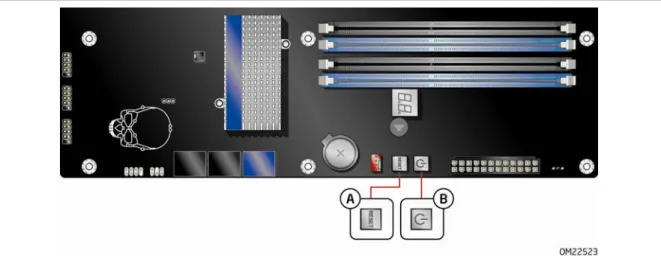
Onboard Power and Reset Buttons
The lighted Power button on the Desktop Board (Figure 4, B) can be used to turn the computer on or off. This button duplicates the function of the front panel power button. To turn off the computer using the onboard Power button, press it for three seconds.
The Power button stays lit when there is standby power still present on the board. This is the case even when the computer appears to be off. For example, when this button is lit, standby power is still present at the memory module sockets and the PCI bus connectors.
CAUTION
If the AC power has been switched off and the onboard power button is still lit, disconnect the power cord before installing or removing any devices connected to the board. Failure to do so could damage the board and any attached devices.
The lighted Reset button on the Desktop Board (Figure 4, A) can be used to reset the board. This button duplicates the function of the front panel Reset button.
25
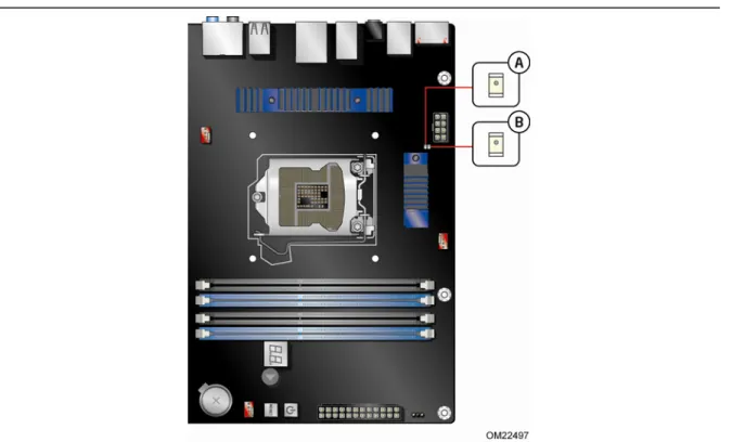
Processor and Voltage Regulator LEDs
The Desktop Board contains two red LEDs (see Figure 5) that indicate the status of the board’s voltage regulation circuitry and the processor:
• The Processor LED (Figure 5, B) indicates an elevated temperature on the processor that could affect performance.
• The Voltage Regulator LED (Figure 5, A) indicates an elevated temperature in the processor voltage regulator circuit that could affect performance.
Diagnostic LEDs
The Desktop Board provides eight LEDs that allow you to monitor the board’s progress through the BIOS Power-on Self-Test (see Figure 6). At initial power on, all the LEDs are off. When the BIOS starts an activity such as memory initialization, the
corresponding LED starts flashing. Once the activity has completed, the LED will remain on.
Table 5. Diagnostic LEDs
Item/Callout
in Figure 6 Activity
LED
Color Description
A Watch Dog Timer Fire/ Back to BIOS
Red When the watch dog timer fires to reset the board, this LED will flash.
In addition, this LED will light and stay on when the Back to BIOS button has been pressed.
B Processor Initialization Green This LED will flash when the processor initialization activity starts. Then the LED will stay on when processor initialization is complete.
C Memory Initialization Green This LED will flash when the memory initialization activity starts. Then the LED will stay on when memory initialization is complete.
D Video Initialization Green This LED will flash when the video initialization activity starts. Then the LED will stay on when video
initialization is complete.
E USB Initialization Green This LED will flash when the USB initialization activity starts. Then the LED will stay on when USB initialization is complete.
F Hard Drive Initialization Green This LED will flash when the hard drive activity starts. Then the LED will stay on when hard drive initialization is complete.
G Option ROM Initialization Green This LED will flash when the option ROM activity starts. Then the LED will stay on when option ROM initialization is complete.
27
Figure 6. Location of the Diagnostic LEDs
Speaker
A speaker is mounted on the Desktop Board. The speaker provides audible error code (beep code) information during the Power-On Self-Test (POST). Refer to Appendix A for a description of the board’s beep codes.
Battery
A battery on the Desktop Board keeps the values in CMOS RAM and the clock current when the computer is turned off. Go to page 57 for instructions on how to replace the battery.
Real-Time Clock
The Desktop Board has a time-of-day clock and 100-year calendar. The battery on the Desktop Board keeps the clock current when the computer is turned off.
29
2 Installing and Replacing Desktop
Board Components
This chapter tells you how to:
• Install the I/O shield
• Install and remove the Desktop Board
• Install and remove a processor
• Install and remove memory
• Install and remove a PCI Express x16 graphics card
• Connect the Serial ATA cables
• Connect to the internal headers
• Connect to the audio system
• Connect chassis fan and power supply cables
• Set the BIOS configuration jumper
• Clear passwords
• Replace the battery
• Install the WiFi/BlueTooth Module
Before You Begin
CAUTIONSThe procedures in this chapter assume familiarity with the general terminology associated with personal computers and with the safety practices and regulatory compliance required for using and modifying electronic equipment.
Disconnect the computer from its power source and from any telecommunications links, networks, or modems before performing any of the procedures described in this chapter. Failure to disconnect power, telecommunications links, networks, or modems before you open the computer or perform any procedures can result in personal injury or equipment damage. Some circuitry on the board can continue to operate even though the front panel power button is off.
Follow these guidelines before you begin:
• Always follow the steps in each procedure in the correct order.
• Set up a log to record information about your computer, such as model, serial numbers, installed options, and configuration information.
• Electrostatic discharge (ESD) can damage components. Perform the procedures described in this chapter only at an ESD workstation using an antistatic wrist strap and a conductive foam pad. If such a station is not available, you can provide some ESD protection by wearing an antistatic wrist strap and attaching it to a metal part of the computer chassis.
Installation Precautions
When you install and test the Intel Desktop Board, observe all warnings and cautions in the installation instructions.
To avoid injury, be careful of:
• Sharp pins on connectors
• Sharp pins on printed circuit assemblies
• Rough edges and sharp corners on the chassis
• Hot components (such as processors, voltage regulators, and heat sinks)
• Damage to wires that could cause a short circuit
Observe all warnings and cautions that instruct you to refer computer servicing to qualified technical personnel.
Prevent Power Supply Overload
Do not overload the power supply output. To avoid overloading the power supply, make sure that the calculated total current loads of all the modules within the computer is less than the output current rating of each of the power supplies output circuits.
Observe Safety and Regulatory Requirements
Read and follow the instructions in this section and the instructions supplied with the chassis and associated modules. If you do not follow these instructions and the instructions provided by the chassis and module suppliers, you increase your safety risk and the possibility of noncompliance with regional laws and regulations. If the instructions for the chassis are inconsistent with these instructions or the instructions for associated modules, contact the supplier to find out how you can ensure that your computer meets safety and regulatory requirements.
31
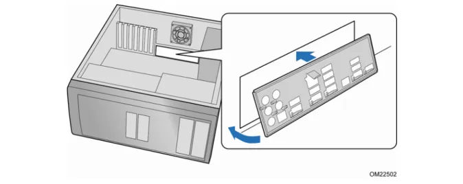
Installing the I/O Shield
The Desktop Board comes with an I/O shield. When installed in the chassis, the shield blocks radio frequency transmissions, protects internal components from dust and foreign objects, and promotes correct airflow within the chassis.
Install the I/O shield before installing the Desktop Board in the chassis. Place the shield inside the chassis as shown in Figure 7. Press the shield into place so that it fits tightly and securely. If the shield does not fit, obtain a properly sized shield from the chassis supplier.
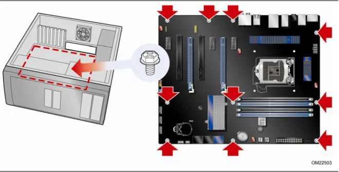
Installing and Removing the Desktop Board
CAUTIONOnly qualified technical personnel should perform this procedure. Disconnect the computer from its power source before performing the procedures described here. Failure to disconnect the power before you open the computer can result in personal injury or equipment damage.
Refer to your chassis manual for instructions on installing and removing the Desktop Board.
Figure 8 shows the location of the mounting screw holes for Intel Desktop Board DP67BG.
33
Installing and Removing a Processor
Instructions on how to install the processor on the Desktop Board are given below.
Installing a Processor
CAUTION
Before installing or removing a processor, make sure the AC power has been removed by unplugging the power cord from the computer. Failure to do so could damage the processor and the board.
To install a processor, follow these instructions:
1. Observe the precautions in "Before You Begin" on page 29.
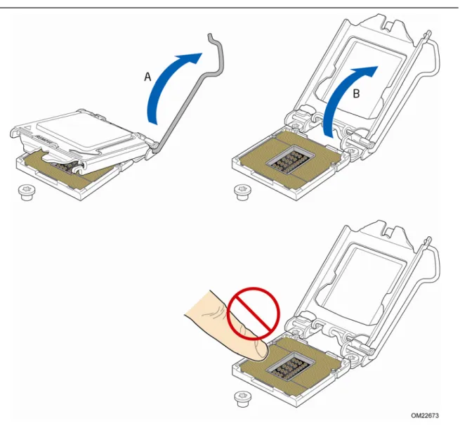
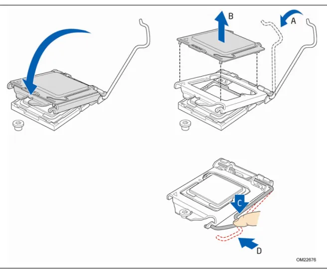
2. Unlatch the processor socket lever by pushing it down and away from the socket (Figure 9, A, B).
3. Rotate the socket lever to lift the load plate away from the socket (Figure 10, A). Make sure that the load plate is in the fully open position (Figure 10, B) while being careful not to damage adjacent components. Do not touch the socket contacts.
35
4. Remove the processor from its protective cover. Hold the processor only at the edges, being careful not to touch the bottom of the processor (see Figure 11).
NOTE
Do not discard the processor cover. Always replace the processor cover if you remove the processor from the socket.
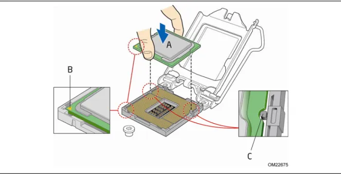
Figure 11. Remove the Processor from the Protective Cover 5. Hold the processor with your thumb and index finger oriented as shown in
Figure 12 to align your fingers with the socket finger cutouts. Make sure that the processor Pin 1 indicator (gold triangle) is aligned with the Pin 1 chamfer on the socket (Figure 12, B) and that the notches on the processor align with the posts on the socket (Figure 12, C). Lower the processor straight down without tilting or sliding it in the socket (Figure 12, A).
7. Carefully lower the socket lever (Figure 13, A) while making sure that the front edge of the load plate slides under the shoulder screw cap as the lever is lowered. Latch the socket lever under the load plate tab (Figure 13, C, D). The socket cover (Figure 13, B) will pop off as shown.
Figure 13. Secure the Load Plate in Place 8. Pick up the socket cover and remove it from the desktop board.
37
Installing the Processor Fan Heat Sink
Intel Desktop Board DP67BG has mounting holes for a processor fan heat sink. For instructions on how to attach the processor fan heat sink to the Desktop Board, refer to the boxed processor manual or boxed thermal solution manual.
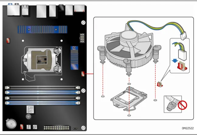
Connecting the Processor Fan Heat Sink Cable
Connect the processor fan heat sink power cable to the 4-pin processor fan header (see Figure 17). A fan with a 4-pin connector as shown in Figure 17 is recommended.
Figure 14. Connecting the Processor Fan Heat Sink Power Cable to the Processor Fan Header
Removing the Processor
For instructions on how to remove the processor fan heat sink and processor, refer to the processor installation manual.
Installing and Removing System Memory
Desktop board DP67BG has four 240-pin DDR3 DIMM sockets arranged in two channels (A and B).
Guidelines for Dual Channel Memory Configuration
Before installing DIMMs, read and follow these guidelines for dual channel memory configuration.
Two or Four DIMMs
Install a matched pair of DIMMs equal in speed and size (see Figure 15) in the blue socket of channel A (DIMM 1) and channel B (DIMM 2).
Figure 15. Example Dual Channel Memory Configuration with Two DIMMs If additional memory is to be used, install another matched pair of DIMMs (see Figure 16) in the black socket of channel A (DIMM 3) and channel B (DIMM 4).
39
Figure 16. Example Dual Channel Memory Configuration with Four DIMMs
Three DIMMs
If you want to use three DIMMs in a dual-channel configuration, install a matched pair of DIMMs equal in speed and size in DIMM 1 and DIMM 3 of channel A. Then install another DIMM equal to the speed and total size of the DIMMs installed in channel A in either DIMM 2 or DIMM 4 of channel B (Figure 17).
Figure 17. Example Dual Channel Memory Configuration with Three DIMMs
NOTE
Installing DIMMs
To make sure you have the correct DIMM, place it on the illustration of the DDR3 DIMM in Figure 18. All the notches should match with the DDR3 DIMM.
41
NOTE
For best memory performance, install memory in the blue DIMM sockets first.
To install a DIMM, follow these steps:
1. Observe the precautions in "Before You Begin" on page 29.
2. Turn off all peripheral devices connected to the computer. Turn off the computer and disconnect the AC power cord.
3. Remove the computer’s cover and locate the DIMM sockets (see Figure 19).
Figure 19. Installing a DIMM
4. Make sure the clips at either end of the DIMM socket(s) are pushed outward to the open position.
5. Holding the DIMM by the edges, remove it from its anti-static package.
6. Position the DIMM above the socket. Align the small notch at the bottom edge of the DIMM with the keys in the socket (see inset in Figure 19).
7. Insert the bottom edge of the DIMM into the socket.
8. When the DIMM is inserted, push down on the top edge of the DIMM until the retaining clips snap into place. Make sure the clips are firmly in place.
Removing DIMMs
To remove a DIMM, follow these steps:
1. Observe the precautions in "Before You Begin" on page 29.
2. Turn off all peripheral devices connected to the computer. Turn off the computer. 3. Remove the AC power cord from the computer.
4. Remove the computer’s cover.
5. Gently spread the retaining clips at each end of the DIMM socket. The DIMM pops out of the socket.
6. Hold the DIMM by the edges, lift it away from the socket, and store it in an anti-static package.
7. Replace the computer’s cover and reconnect the AC power cord.
Installing and Removing PCI Express x16
Graphics Cards
Installing a PCI Express x16 Graphics Card
CAUTION
When installing a PCI Express card, ensure that the card is fully seated in the PCI Express connector before you power on the system. If the card is not fully seated in the connector, an electrical short may result across the connector pins. Depending on the over-current protection of the power supply, certain Desktop Board components and/or traces may be damaged.
43
Follow these instructions to install a PCI Express x16 graphics card: 1. Observe the precautions in "Before You Begin" on page 29.
2. Place the card in the PCI Express x16 connector (Figure 20, A) and press down on the card until it is completely seated in the connector and the card retention notch on the card snaps into place around the retention mechanism pin on the connector. 3. Secure the card’s metal bracket to the chassis back panel with a screw
(Figure 20, B).
4. Connect the monitor cable to the graphics card according to the manufacturer’s instructions.
Removing a PCI Express x16 Graphics Card
Follow these instructions to remove a PCI Express x16 graphics card from a connector: 1. Observe the precautions in "Before You Begin" on page 29.
2. Remove the screw (Figure 21, A) that secures the card’s metal bracket to the chassis back panel.
3. Push the card ejector lever down using the tip of a pencil or similar tool
(Figure 21, B) in the notch. This will release the card from the connector (C). 4. Pull the card straight up to remove it.
Figure 21. Removing a PCI Express x16 Graphics Card
45
To install two linked PCI Express graphics cards:
1. Observe the precautions in "Before You Begin" on page 29.
2. Install the first card in the PCI Express x16 connector as described in “Installing a PCI Express x16 Graphics Card” on page 42.
3. Place the second card in the secondary PCI Express x16 connector (Figure 22, A) and press down on the card until it is completely seated in the connector and the card retention notch on the card snaps into place around the retention mechanism pin on the connector.
4. Secure the card’s metal bracket to the chassis back panel with a screw (Figure 22, B).
5. Connect the two cards together with the SLI bridge (Figure 22, C) as shown. 6. Connect the monitor cable to the graphics card according to the manufacturer’s
instructions.
Figure 22. Installing Linked PCI Express Graphics Cards For more complete installation and configuration information refer to the
Connecting the Serial ATA (SATA) Cables
SATA cables support the Serial ATA protocol. Each cable can be used to connect one internal SATA drive to the Desktop Board. For correct cable function:
1. Observe the precautions in “Before You Begin” on page 29.
2. Attach one end of the SATA cable to one of the SATA connectors on the board (Figure 23, A) and attach the other end of the cable to the SATA drive
(Figure 23, B).
47
Connecting to the Internal Headers
Before connecting cables to any of the internal headers, observe the precautions in “Before You Begin” on page 29. Figure 24 shows the location of the internal headers and connectors on Intel Desktop Board DP67BG.
S/PDIF Header
Figure 24, A shows the location of the S/PDIF output header. Table 6 shows the pin assignments and signal names for the S/PDIF connector.
Table 6. S/PDIF Header Signal Names
Pin Description
1 Ground
2 S/PDIF Out
3 Key (no pin)
4 +5 VDC
IEEE 1394a Header
Figure 24, B shows the location of the IEEE 1394a header. Table 7 shows the pin assignments and signal names for the IEEE 1394a header.
Table 7. IEEE 1394a Header Signal Names
Pin Signal Name Pin Signal Name
1 TPA1+ 2 TPA1-
3 Ground 4 Ground
5 TPA2+ 6 TPA2-
7 +12 V 8 +12 V
9 Key (no pin) 10 Ground
Front Panel Intel HD Audio Header
Figure 24, C shows the location of the front panel Intel HD Audio header. Table 8 shows the pin assignments and signal names for the front panel Intel HD Audio header.
Table 8. Front Panel Intel HD Audio Header Signal Names
Pin Signal Name Pin Signal Name
1 PORT 1L 2 GND
49
Alternate Front Panel Power LED Header
Figure 24, D shows the location of the alternate front panel power LED header. Pins 1 and 3 of this header duplicate the signals on pins 2 and 4 of the front panel header. If your chassis has a three-pin power LED cable, connect it to this header. Table 9 shows the pin assignments for the alternate front panel header.
Table 9. Alternate Front Panel Power LED Header Signal Names
Pin Signal Name In/Out
1 Front panel green LED Out
2 No pin
3 Front panel yellow LED Out
Consumer IR (CIR) Headers
The Desktop Board has two CIR headers: the input or receiver header (Figure 24, F) and the output or emitter header (Figure 24, E). The receiver header consists of a filtered translated infrared input compliant with Microsoft CIR specifications and a “learning” infrared input. The learning input is a high-pass input which the computer can use to “learn” to speak the infrared communication language of other user
remotes. The emitter header consists of two output ports which the computer can use to emulate “learned” infrared commands in order to control external electronic
hardware.
NOTE
The Consumer IR option must be enabled in the system BIOS before it can function. Press <F2> at boot to enter the system BIOS, and go to Advanced > Peripheral Configuration > Enhanced Consumer IR, and set this option to Enabled.
Table 10 shows the pin assignments and signal names for the front panel CIR receiver (input) header and Table 11 shows the pin assignments and signal names for the back panel CIR emitter (output) header.
Table 10. Front Panel CIR Receiver (Input) Header Signal Names
Pin Signal Name Pin Signal Name
1 Ground 2 LED
3 No Connection 4 Learn-In
5 +5 V Standby 6 Vcc
Table 11. Back Panel CIR Header Emitter (Output) Header Signal Names
Pin Signal Name Pin Signal Name
1 Emitter Out 1 2 Emitter Out 2
3 Ground 4 Key (no pin)
5 Jack Detect 1 6 Jack Detect 2
USB 2.0 Headers
Figure 24, G shows the location of the USB 2.0 headers. Table 12 shows the pin assignments and signal names for each USB 2.0 header. Each USB header can be used to connect two USB devices.
Table 12. USB 2.0 Header Signal Names
USB Port A USB Port B Pin Signal Name Pin Signal Name
1 Power (+5 V) 2 Power (+5 V) 3 D- 4 D- 5 D+ 6 D+ 7 Ground 8 Ground 9 Key 10 No Connection NOTE
Computer systems that have an unshielded cable attached to a USB port might not meet FCC Class B requirements, even if no device or a low-speed USB device is attached to the cable. Use a shielded cable that meets the requirements for a full-speed USB device.
51
Front Panel Header
Figure 24, H shows the location of the front panel header. Table 13 shows the pin assignments and signal names for the front panel header.
Table 13. Front Panel Header Signal Names
Pin Description In/Out Pin Description In/Out Hard Drive Activity LED Power LED
1 Hard disk LED pull-up to +5 V Out 2 Front panel green LED Out 3 Hard disk active LED Out 4 Front panel yellow LED Out
Reset Switch On/Off Switch
5 Ground 6 Power switch In
7 Reset switch In 8 Ground
Power Not Connected
9 Power Out 10 No pin
NOTE
When connecting individual wires from your chassis front panel to the front panel header, be sure to observe the connection polarity. Positive wires are usually solid color and negative wires are usually white or striped.
Chassis Intrusion Header
Figure 24, I shows the location of the chassis intrusion header. This header can be connected to a mechanical switch on the chassis to detect if the chassis cover is removed. This switch should be in the open position when the chassis cover is installed and closed when the cover is removed.
Table 14 shows the pin assignments and signal names for the chassis intrusion header.
Table 14. Chassis Intrusion Header Signal Names
Pin Description
1 Intruder# 2 Ground
Connecting to the Audio System
After installing the Realtek audio driver from the Intel® Express Installer DVD-ROM, the multi-channel audio feature can be enabled. Figure 25 shows the back panel audio connectors. The default connector assignments are shown in the table.
Item Description
A Rear surround speakers
B S/PDIF output (optical)
C Center/subwoofer
D Line in
E Front speakers
F Mic in
Figure 25. Back Panel Audio Connectors
NOTE
The back panel line out connector is designed to power either headphones or amplified speakers only. Poor audio quality may occur if passive (non-amplified) speakers are connected to this output.
53
Connecting Chassis Fan and Power Supply
Cables
Connecting Chassis Fan Cables
Connect chassis fan cables to the chassis fan headers on the Desktop Board. Figure 26 shows the location of the chassis fan headers.
Connecting Power Supply Cables
Figure 27 shows the location of the power connectors.
CAUTION
Failure to use an appropriate power supply and/or not connecting the 12 V
(Figure 27, A) power connector to the Desktop Board may result in damage to the board or the system may not function properly.
The 2 x 12 pin main power connector (Figure 27, C) is backwards compatible with ATX12V power supplies with 2 x 10 connectors.
55
1. Observe the precautions in "Before You Begin" on page 29.
2. Connect the 12 V processor core voltage power supply cable to the 2 x 4 pin connector (Figure 27, A).
3. Connect the main power supply cable to the 2 x 12 pin connector (Figure 27, C).
Setting the BIOS Configuration Jumper
NOTEAlways turn off the power and unplug the power cord from the computer before moving the jumper. Moving the jumper with the power on may result in unreliable computer operation.
Figure 28 shows the location of the Desktop Board’s BIOS configuration jumper block.
Figure 28. Location of the BIOS Configuration Jumper Block
The three-pin BIOS jumper block enables board configuration to be done in the BIOS Setup program. Table 15 shows the jumper settings for the BIOS Setup program modes.
Table 15. Jumper Settings for the BIOS Setup Program Modes
Jumper Setting Mode Description
Normal (default) (1-2) The BIOS uses the current configuration and passwords for booting.
Configure (2-3) After the Power-On Self-Test (POST) runs, the BIOS displays the Maintenance Menu. Use this menu to clear passwords.
Recovery (None) The BIOS recovers data in the event of a failed BIOS update.
Clearing Passwords
This procedure assumes that the board is installed in the computer and the configuration jumper block is set to normal mode.
1. Observe the precautions in "Before You Begin" on page 29.
2. Turn off all peripheral devices connected to the computer. Turn off the computer. Disconnect the computer’s power cord from the AC power source (wall outlet or power adapter).
3. Remove the computer cover.
4. Find the configuration jumper block (see Figure 28). 5. Place the jumper on pins 2-3 as shown below.
57
10.Turn off the computer. Disconnect the computer’s power cord from the AC power source.
11.Remove the computer cover.
12.To restore normal operation, place the jumper on pins 1-2 as shown below.
13.Replace the cover, plug in the computer, and turn on the computer.
Replacing the Battery
A coin-cell battery (CR2032) powers the real-time clock and CMOS memory. When the computer is not plugged into a wall socket, the battery has an estimated life of three years. When the computer is plugged in, the standby current from the power supply extends the life of the battery. The clock is accurate to ± 13 minutes/year at 25 ºC with 3.3 VSB applied.
When the voltage drops below a certain level, the BIOS Setup program settings stored in CMOS RAM (for example, the date and time) might not be accurate. Replace the battery with an equivalent one. Figure 29 on page 62 shows the location of the battery.
CAUTION
Risk of explosion if the battery is replaced with an incorrect type. Batteries should be recycled where possible. Disposal of used batteries must be in accordance with local environmental regulations.
PRÉCAUTION
Risque d'explosion si la pile usagée est remplacée par une pile de type incorrect. Les piles usagées doivent être recyclées dans la mesure du possible. La mise au rebut des piles usagées doit respecter les réglementations locales en vigueur en matière de protection de l'environnement.
FORHOLDSREGEL
Eksplosionsfare, hvis batteriet erstattes med et batteri af en forkert type. Batterier bør om muligt genbruges. Bortskaffelse af brugte batterier bør foregå i
overensstemmelse med gældende miljølovgivning. OBS!
Det kan oppstå eksplosjonsfare hvis batteriet skiftes ut med feil type. Brukte batterier bør kastes i henhold til gjeldende miljølovgivning.
VIKTIGT!
Risk för explosion om batteriet ersätts med felaktig batterityp. Batterier ska kasseras enligt de lokala miljövårdsbestämmelserna.
VARO
Räjähdysvaara, jos pariston tyyppi on väärä. Paristot on kierrätettävä, jos se on mahdollista. Käytetyt paristot on hävitettävä paikallisten ympäristömääräysten mukaisesti.
VORSICHT
Bei falschem Einsetzen einer neuen Batterie besteht Explosionsgefahr. Die Batterie darf nur durch denselben oder einen entsprechenden, vom Hersteller empfohlenen Batterietyp ersetzt werden. Entsorgen Sie verbrauchte Batterien den Anweisungen des Herstellers entsprechend.
AVVERTIMENTO
Esiste il pericolo di un esplosione se la pila non viene sostituita in modo corretto. Utilizzare solo pile uguali o di tipo equivalente a quelle consigliate dal produttore. Per disfarsi delle pile usate, seguire le istruzioni del produttore.
PRECAUCIÓN
Existe peligro de explosión si la pila no se cambia de forma adecuada. Utilice
solamente pilas iguales o del mismo tipo que las recomendadas por el fabricante del equipo. Para deshacerse de las pilas usadas, siga igualmente las instrucciones del fabricante.
WAARSCHUWING
Er bestaat ontploffingsgevaar als de batterij wordt vervangen door een onjuist type batterij. Batterijen moeten zoveel mogelijk worden gerecycled. Houd u bij het weggooien van gebruikte batterijen aan de plaatselijke milieuwetgeving. ATENÇÃO
Haverá risco de explosão se a bateria for substituída por um tipo de bateria incorreto. As baterias devem ser recicladas nos locais apropriados. A eliminação de baterias usadas deve ser feita de acordo com as regulamentações ambientais da região. AŚCIAROŽZNAŚĆ
59
UPOZORNÌNÍ
V případě výměny baterie za nesprávný druh může dojít k výbuchu. Je-li to možné, baterie by měly být recyklovány. Baterie je třeba zlikvidovat v souladu s místními předpisy o životním prostředí.
Προσοχή
Υπάρχεικίνδυνος γιαέκρηξη σεπερίπτωση πουημπαταρίααντικατασταθεί απόμία λανθασμένουτύπου. Οιμπαταρίες θαπρέπεινα ανακυκλώνονταιότανκάτιτέτοιοείναι δυνατό. Η απόρριψητωνχρησιμοποιημένων μπαταριώνπρέπεινα γίνεταισύμφωναμε τουςκατάτόποπεριβαλλοντικούςκανονισμούς. VIGYÁZATHa a telepet nem a megfelelő típusú telepre cseréli, az felrobbanhat. A telepeket lehetőség szerint újra kell hasznosítani. A használt telepeket a helyi környezetvédelmi előírásoknak megfelelően kell kiselejtezni.
AWAS
Risiko letupan wujud jika bateri digantikan dengan jenis yang tidak betul. Bateri sepatutnya dikitar semula jika boleh. Pelupusan bateri terpakai mestilah mematuhi peraturan alam sekitar tempatan.
OSTRZEŻENIE
Istnieje niebezpieczeństwo wybuchu w przypadku zastosowania niewłaściwego typu baterii. Zużyte baterie należy w miarę możliwości utylizować zgodnie z odpowiednimi przepisami ochrony środowiska.
PRECAUŢIE
Risc de explozie, dacă bateria este înlocuită cu un tip de baterie necorespunzător. Bateriile trebuie reciclate, dacă este posibil. Depozitarea bateriilor uzate trebuie să
ВНИМАНИЕ
При использованиибатареинесоответствующеготипасуществуетрискеевзрыва.
Батареидолжныбыть утилизированыповозможности. Утилизация батарейдолжна
проводится поправилам, соответствующимместнымтребованиям.
UPOZORNENIE
Ak batériu vymeníte za nesprávny typ, hrozí nebezpečenstvo jej výbuchu. Batérie by sa mali podľa možnosti vždy recyklovať. Likvidácia použitých batérií sa musí vykonávať
v súlade s miestnymi predpismi na ochranu životného prostredia. POZOR
Zamenjava baterije z baterijo drugačnega tipa lahko povzroči eksplozijo.
Če je mogoče, baterije reciklirajte. Rabljene baterije zavrzite v skladu z lokalnimi okoljevarstvenimi predpisi.
.
UYARI
Yanlış türde pil takıldığında patlama riski vardır. Piller mümkün olduğunda geri dönüştürülmelidir. Kullanılmış piller, yerel çevre yasalarına uygun olarak atılmalıdır.
OСТОРОГА
Використовуйтебатареї правильноготипу, інакшеіснуватимеризик вибуху.
Якщоможливо, використані батареї слідутилізувати. Утилізація використаних
To replace the battery, follow these steps:
1. Observe the precautions in "Before You Begin" (see page 29).
2. Turn off all peripheral devices connected to the computer. Disconnect the
computer’s power cord from the AC power source (wall outlet or power adapter). 3. Remove the computer cover.
4. Locate the battery on the board (see Figure 29).
5. With a medium flat-bladed screwdriver, gently pry the battery free from its connector. Note the orientation of the “+” and “-” on the battery.
6. Install the new battery in the connector, orienting the “+” and “-” correctly. 7. Replace the computer cover.
63
Installing the WiFi/Bluetooth* Module in a
Desktop Chassis
NOTE
The WiFi/Bluetooth*module is supplemental hardware that is included with certain Desktop Boards. Additional WiFi/Bluetooth modules can be ordered online from
Installing the WiFi/Bluetooth module that is shipped with Intel Desktop Board DP67BG in your desktop system allows you to connect to wireless networks and Bluetooth peripherals.
The recommended installation procedure for a typical desktop chassis is as follows: 1. Observe the precautions in "Before You Begin" on page 29.
2. Make sure that the system is turned off and disconnected from its power source. 3. Remove the plastic cover from an empty 5-1/4 inch drive bay in the chassis bezel
(Figure 30, A).
4. Remove the metal filler plate from the internal drive bay (Figure 30, B).
5. Remove the paper backing covering the adhesive on the back of the WiFi/Bluetooth Module and attach the module to the back side of the plastic drive bay cover
(Figure 30, C).
6. Connect one end of the USB cable to the connector on the front of the module (Figure 30, D).
7. Reinstall the plastic drive bay cover in the chassis bezel while routing the USB cable into the chassis through the empty drive bay (Figure 30, E).
8. Connect the free end of the USB cable to an unused front panel USB header on the Desktop Board (see Figure 1, DD for locations) (Figure 30, F).