Controlled Manipulation of Engineered Colloidal Particles
Janine Nunes
A dissertation submitted to the faculty of the University of North Carolina at Chapel Hill in partial fulfillment of the requirements for the degree of Doctor of Philosophy in the
Department of Chemistry
Chapel Hill 2010
Approved by Joseph M. DeSimone
Edward T. Samulski Michael Rubinstein
ii © 2010 Janine Nunes
iii Abstract
Janine Nunes: Controlled Manipulation of Engineered Colloidal Particles (Under the direction of Joseph M. DeSimone)
This research utilized the Particle Replication in Non-wetting Templates (PRINT®) technology to fabricate highly tailored colloidal particles. The behavior of these engineered particles were studied as they were subjected to different precisely controlled external influences, including electric fields, magnetic fields and a templating approach based on the PRINT process. Given the tunability in particle properties afforded by the PRINT process, exceptional control of the resulting particle assemblies and particle mobility were observed, suggesting potential applications in numerous materials and life science applications that require control on the nanoscale.
As the PRINT process was integral to all aspects of this research, it was important to gain a clear understanding of mechanism by which perfluoropolyether (PFPE) elastomeric molds can generate monodisperse arrays of discrete, uniform particles with tailored size, shape and composition. Thus, fundamental studies were conducted on the PFPE elastomers, focusing on contact mechanics measurements and capillary flow experiments. The results confirmed the low surface energy of PFPE, an important property that renders the PFPE molds ideal for the PRINT process. Capillary flow experiments were conducted to study the method by which PFPE molds can be filled during the PRINT process. The flow in closed PFPE microchannels was compared to that in PDMS and glass.
iv
presence of electric and magnetic fields. Electric field experiments were conducted using non-uniform alternating current electric fields and uniform direct current electric fields. Magnetic field experiments were conducted using both stationary and rotating magnetic fields. Particle assemblies were observed to form and could be tuned by particle shape and composition. Particle motion, both translational and rotational, was also controlled. Properties were found to be both shape and composition dependent. These experiments were applied to the fabrication of steerable micromotors and the driving of deformable particles through confined environments.
v
To my brother, Justin Nunes (1984 – 2007), you were the best part of all of us To my mother, Beverly Nunes
vi
Acknowledgements
There are many people to whom I wish to convey my heartfelt gratitude. First, I would like to thank my advisor, Joseph DeSimone, for providing an opportunity to learn and work in a wonderful research environment. A significant amount of the work documented in this dissertation was conducted jointly with Dr. Kevin P. Herlihy, and I am forever grateful for his great ideas and motivating approach to research. I am extremely grateful for Elizabeth Enlow - for her willingness to serve as counselor, brainstorming partner, advisor and great friend. I would also like to thank Kelly Chang, who has always been willing to listen or advise as necessary. Over the years, I have had the opportunity to work with different postdoctoral associates in the DeSimone group: Dr. Benjamin Maynor, Dr. Alexander Ermoshkin, Dr. Libin Du and Dr. Merve Ertas. I thank them all for their advice and assistance. I enjoyed the collaborative atmosphere in the group and I have benefited from the knowledge and expertise of many group members who I wish to acknowledge, including Dr. Stuart Williams, Dr. Meredith Hampton, Dr. Jennifer Kelly, Ron Traud, Dr. Zhaokang Hu, Tim Merkel, Dr. Stephanie Gratton, Dr. Henry Zhang Dr. Candice Brannen and Dr. Patricia Ropp.
vii
Experiments, so I would like to thank Professor Richard Superfine and his students, Lamar Mair, Briana Fiser, Adam Shields and Jeremy Cribb. I would also like to express my gratitude to the personnel at the different user facilities that I worked at: Dr. Carrie Donley, Dr. Amar Kumbhar and Dr. Wallace Ambrose at the Chapel Hill Analytical and Nanofabrication Lab (CHANL); Dr. Kirk Bryson, Dr. Jay Dalton and Dr. Mark Walters at the Shared Materials Instrument Facility (SMIF, Duke University); David Vellenga and Chris Hardiman at the Nanofabrication Facility in North Carolina State University. Collin McKinney of the Department of Chemistry Electronics Facility has also been a great help.
On a personal note, I am so grateful for my family and friends. My mother and brothers have been the most amazing support system and any success that I have achieved has been because of them. It has been challenging being far away from them for so long, especially when faced with difficult times.
viii
Table of Contents
Page
List of Tables ... xxii
List of Figures ... xxiii
List of Abbreviations and Symbols... xix
Chapter 1. Introduction to the Manipulation of Colloids ...1
1.1 Overview ...2
1.2 Particle Fabrication Methodologies ...4
1.2.1 Shape Anisotropy ...5
1.2.2 Chemical Anisotropy ...9
1.3 Autonomous Particle Manipulation ...12
1.3.1 Controlled Aggregation ...12
1.3.2 Catalytic Motion ...17
1.3.3 Fluidic Assembly ...20
1.4 Externally Controlled Field Driven Manipulation of Colloids ...21
1.4.1 Electric Fields ...21
1.4.1.1 Electrophoresis and Electroosmosis ...22
1.4.1.2 Dielectrophoresis ...24
1.4.2 Magnetic Fields ...26
1.4.3 Optical Fields...27
1.5 Applications ...29
1.5.1 Smart Fluids...29
1.5.2 Photonic Crystals ...30
1.5.3 Micro-electronics ...30
1.5.4 Micro-Pumps and Micro-Motors for Lab-on-a-Chip Machinery ...31
ix
1.5.6 In vivo Transport/Therapeutic Delivery ...32
1.5.7 Particle-based Display Technologies ...32
1.6 Summary ...33
1.7 References ...36
Chapter 2. PRINT® Technology and PFPE Characterization ...44
2.1 Introduction ...45
2.1.1 PRINT Technology ...45
2.1.2 Solid Surface Energy Measurements ...47
2.1.3 Capillary Flow ...49
2.2 Research Objectives ...50
2.3 Experimental ...51
2.3.1 PFPE Synthesis ...51
2.3.2 Contact Angle and Mechanical Characterization of PFPE Elastomers ...52
2.3.3 JKR Studies ...53
2.3.3.1 Experimental Procedure ...53
2.3.3.2 Results and Discussion ...57
2.3.4 Capillary Flow Experiments ...62
2.3.4.1 Experimental Procedure ...62
2.3.4.2 Results and Discussion ...63
2.4 Conclusion ...65
2.5 References ...67
Chapter 3. Electrical Manipulation of PRINT Particles ...69
3.1 Specific Research Objectives ...70
3.2 Dielectrophoretic Assembly of PRINT Particles ...70
3.2.1 Particle Fabrication and Characterization ...70
3.2.2 Experimental Design and Set-up ...73
3.2.3 Results and Discussion ...75
3.3 Particle Electrophoresis in Confined Geometries ...87
3.3.1 Particle Fabrication and Characterization ...87
x
3.3.3 Results and Discussion ...91
3.4 Summary and Future Outlook ...94
3.5 References ...96
Chapter 4. Magnetic Manipulation of PRINT Particles ...97
4.1 Specific Research Objectives ...98
4.2 Experimental ...99
4.2.1 Particle Fabrication and Characterization ...99
4.2.2 Magnetic Chaining Experiments ...103
4.2.3 SQUID Experiments ...103
4.2.4 Magnetic Stage Set-up for Imaging Particle Rotation and Chaining in Water ...104
4.2.5 Particle Polymerization Experiment ...104
4.2.6 Magnetic Stage Set-up for Particle Tracking Experiments in H2O2 ...105
4.3 Results and Discussion ...106
4.3.1 Magneto-Polymer PRINT Composite Particles ...106
4.3.2 Magnetic Manipulation of Microscale Composite Particles ...114
4.3.3 End-labeling Composite Particles for Use as Micromotors ...119
4.4 Summary and Future Outlook ...124
4.5 References ...126
Chapter 5. Hierarchically Controlled PRINT Composite Thin Films ...127
5.1 Specific Research Objectives ...128
5.2 Experimental ...129
5.2.1 Materials and Instrumentation ...129
5.2.2 Ordered Composite Film Fabrication and Characterization ...131
5.2.2.1 Crosslinked Polymer/Polymer Systems ...132
5.2.2.1.1 Fabrication ...132
5.2.2.1.2 Characterization ...133
5.2.2.2 Thermoplastic Polymer Systems...138
5.2.2.2.1 Fabrication ...138
5.2.2.2.2 Characterization ...140
xi
5.2.2.3.1 Barium Titanate Sol-gel Synthesis...142
5.2.2.3.2 Bulk Ceramic Synthesis and Characterization ...142
5.2.2.3.3 BaTiO3 Particle Array Fabrication and Characterization ...144
5.2.2.3.4 Polymer/BaTiO3 Composite Film Fabrication and Characterization ...147
5.2.2.4 Polymer/Metal...152
5.4 Conclusions and Future Outlook ...153
xii List of Tables
Table 1.1 Selected applications that utilize controlled colloidal manipulation techniques ...33
Table 2.1 Water contact angle data ...53
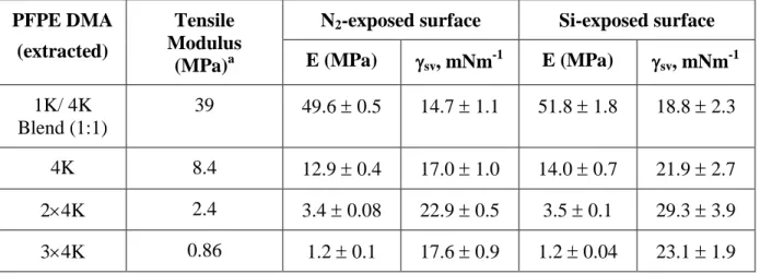
Table 2.2 Results for unextracted PFPE samples ...59
Table 2.3 Results for PFPE samples extracted in solkane ...60
Table 2.4 Permeability of PFPE compared with PDMS ...65
Table 3.1 Particle properties ...78
Table 3.2 Zeta potential measurements of rod particles ...88
Table 4.1 Saturation magnetization of B3 particles ...113
Table 4.2 Composite particle polymerization experimental results ...119
Table 4.3 Particle translational velocities for all particle sizes under a stationary magnetic field (no field) with varying solutions of H2O2 ...122
Table 5.1 Summary of Ordered Composite Films ...131
xiii List of Figures
Figure 1.1. SEM and TEM images of different types of particles illustrating four of the major particle shape classes: Top row – Spherical and derivatives where (a) are PS latex spheres, (b) clusters of PS microspheres with triangular dipyramid structure, (c) PS ellipsoids and (d) PS disks. Second row – Polyhedra shapes where (e) are silver right bipyramids, (f) silver nanocubes, (g) silver octahedrons, and (h) truncated silver octahedrons. Third row – Branched and filamentous structures where (i) are CdSe/CdS nanotetrapods, (j) gold nanorods, (k) worm-like micellar structures of blends of different molecular weight PS-b-PEO copolymers, and (l) cross-linked PEG nanoworms. Fourth row – Lithographically-defined particle shapes where (m) rough side wall cylinders, (n) fenestrated hexagons, (o) arrow-shaped particles,and (p) open ring structure. ...8 Figure 1.2. Chemical anisotropy in different particle systems. Left panel shows bulk
chemical anisotropy, and right panel shows surface chemical anisotropy, where (a) triphasic Au-CdSe-Au nanorods, (b) bi-colored particles with half containing carbon black and the other half containing titanium dioxide, (c) triphasic triangular particles fabricated with
hydrodynamic focusing lithography, (d) blend particles of PS-b-PB and homopolymer PS, (e) superparamagnetic composite colloids with SiO2-coated Fe3O4 core and a PS shell, (f)
superparamagnetic composite colloids with SiO2-coated Fe3O4 nanoparticle chains in PEG DA microspheres, (g) Janus particle formed using a glucose partial protecting layer, (h) gold patches deposited on polystyrene particles, (i) crosslinked EPTA particles with PS patches, (j) striped mixed SAM on gold nanoparticle, (k) end-functionalized PRINT cylindrical
particles and (l) colloidosome Janus particles. ...11 Figure 1.3. Process utilizing templating and capillary forces. A) Illustration of the templating process; B, C) 2D lattices assembled from 1.75 µm PS beads in channels 10.0 and 10.5 µm, respectively; D) Double layered zig-zag chains formed by assembling PS beads in an array of channels (direction of flow indicated by arrow); E) Particle aggregate after annealing and release from the template shown in D. ...17 Figure 1.4. Example where fluidic assembly is used to assemble microdevices onto a plastic substrate. A) Overview of process; B) Closer detailed view; C) Collected freestanding single crystal silicon FETs; D) triangular FETs; E) cross-shaped FETs; F) Plastic substrate with empty binding sites; G) Substrate after assembly with transistor and resistor in place ...21 Figure 1.5. Schematic illustration of the three electric field phenomena: A) Positively
xiv
nm PS spheres (in water) assembled into a star configuration with dynamic optical trapping
patterns. ...28
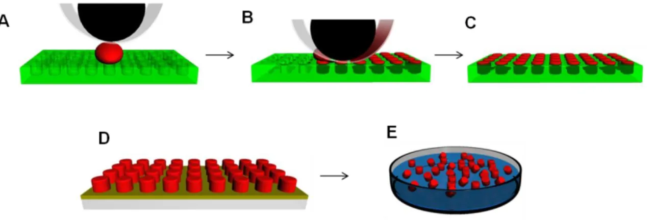
Figure 2.1. Schematic representation of the PRINT process. A) Roller is brought into contact with the particle precursor and the mold; B) Roller evenly distributes the precursor into cavities of mold. Excess liquid is pulled away by the high surface energy polymer sheet; C) Liquid is solidified in the mold to form particles; D) Particles are removed from the mold; E) Particles are collected in solution. ...46
Figure 2.2. PFPE DMA ...47
Figure 2.3. Contact interaction of a semi-sphere and planar surface, where the radius of deformation, a, is a function of the load, P. ...49
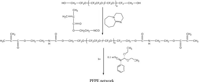
Figure 2.4. Reaction scheme for PFPE-DMA from the PFPE diol ...52
Figure 2.5. Chain extension reaction to form 2 PFPE diol ...52
Figure 2.6. Preparation of PFPE lenses ...54
Figure 2.7. Optical side view image of the PFPE lens ...55
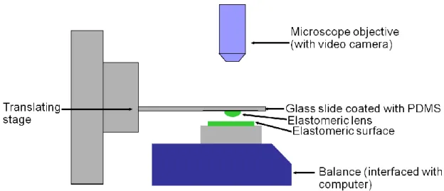
Figure 2.8. Schematic representation of the JKR experimental apparatus ...56
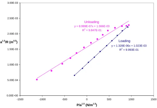
Figure 2.9. Plot of a3/2/R versus P/a3/2 for 34K PFPE ...58
Figure 2.10. Plot of a3/2/R versus P/a3/2 for extracted 4K PFPE ...58
Figure 2.11. Experimental set-up for capillary flow experiment ...63
Figure 2.12. (a) Advancing liquid-air interface in dead-end PFPE micro-channels of different lengths and (b) Advancing liquid-air interface in dead-end PFPE and PDMS microchannels (25 m 38 m 6 mm) ...64
Figure 3.1. Representative scanning electron micrograph and fluorescent images of (from left to right) 2.5 x 1 m hexnut particles with 1 m hole, 1.6 x 1.6 x 5 m trapezoidal particles, 6.5 x 0.8 m disk-shaped particles, 9.6 x 3.4 x 1 m boomerang-shaped particles. Scale bars represent 2 m. ...73
Figure 3.2. Illustration of the dielectrophoretic cell ...74
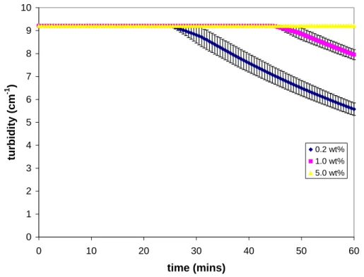
Figure 3.3. Turbidity measurements on 5 mg/mL hexnut suspensions at three CTAB concentrations: 0.2 wt%, 1.0 wt% and 5.0 wt% ...75
Figure 3.4. Turbidity curves for aqueous particle suspensions containing 1.0 wt% CTAB where A) 5 mg/mL hexnut suspension, B) 10 mg/mL rod suspension, C) 20 mg/mL disk suspension, and D) 10 mg/mL boomerang suspension ...77
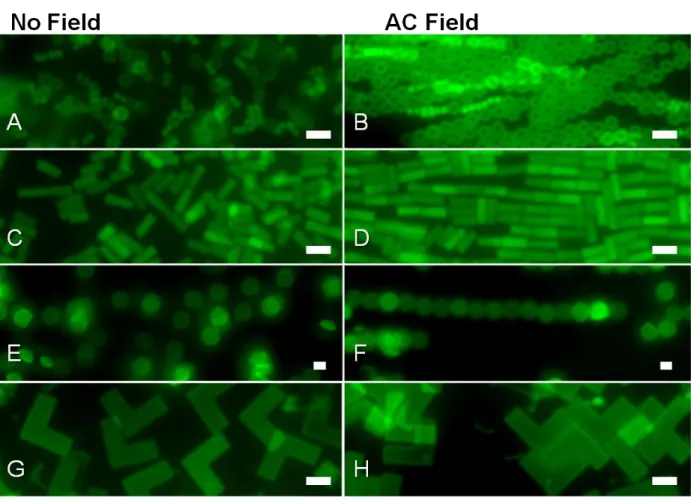
Figure 3.5. Representative fluorescence images of randomly dispersed (A, C, E, G) and electrically aligned (B, D, F, H) particles with a 5 m scale bar. Particles shown were aligned at 40-50 V and 500 Hz ...79
xv
Figure 3.7. Fluorescence images of aligned particles with applied AC electric field. 5 m scale bar. Particles shown were aligned in a 40-50 V field at 500 Hz ...83 Figure 3.8. Low magnification fluorescence images of particle alignment in nonuniform AC electric field for (A) hexnut, (B) rod, (C) disk and (D) boomerang shaped particle
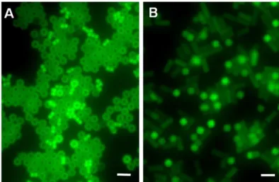
suspensions ...85 Figure 3.9. Fluorescence image of (A) hexnut and (B) rod shaped particles with applied AC electrical field on the electrode. 5 m scale bar ...86 Figure 3.10. PVP/PEG composite formed in DEP cell ...87 Figure 3.11. SEM images of the rigid particle series (A) 2.8×2.8×0.9 µm (AR = 0.3), (B) 2.8×2.8×2.2 µm (AR = 0.8) and (C) 2.8×2.8×6.5 µm (AR = 2.3) ...88 Figure 3.12. Deformable CEA particles image (A) DIC image of dried drop of particles, and (B, C) SEM images of particles dried on a woven fiber membrane ...89 Figure 3.13. Two types of microfluidic channels where (A) is a straight channel design and (B) is a microchannel design with patterned gaps ...90 Figure 3.14. Third type of microfluidic device consisting of a cubic feature array ...91 Figure 3.15. Particle speed as function of electric field strength for positively charged
2.8×2.8×0.9 µm particles suspended in (A) 1 wt% CTAB and (B) 1 wt% Pluronic ...92 Figure 3.16. Particle speed as function of electric field strength for negatively charged
particles suspended in 1 wt% Pluronic, where the particle sizes are (A) 2.8×2.8×2.2 µm (AR = 0.8) and (B) 2.8×2.8×6.5 µm (AR = 2.3) ...92 Figure 3.17. Optical image of a patterned microchannel with particles moving towards the negative electrode (E field strength = 1.25 V/cm). Clogging was present near some of the gaps ...93 Figure 3.18. Bright field images of particle crystallization occurring near the negative
electrode (Field strength = 2.5 V/cm) ...93 Figure 3.19. DIC images of deformable particles in 5 µm array ...94 Figure 4.1. TEM images of the magnetite samples used in the PRINT composite (A)
xvi
Figure 4.4. SEM (A-C) and TEM (D-F) images of PRINT magneto-polymer nanoparticles on the harvesting layer and collected from solution, respectively. (A,D) are 80 × 2000 nm worm particles, (B,E) are 80 × 320 nm rice particles, and (C,F) are 200 × 200 nm cylindrical
particles ...107 Figure 4.5. Fluorescent micrograph of particles in the mold containing (A) 1, (B) 10, and (C) 50 wt% magnetite particles. Aggregates of magnetite are visible in the particles as dark spots in the green fluorescent polymer background ...108 Figure 4.6. A schematic representation of the PRINT process where (A) is the PFPE mold (shown in green) and pre-particle solution (shown in red) containing randomly dispersed Fe3O4, (B) shows the full mold placed in a magnetic field created by two permanent magnets and linear aggregates of Fe3O4 are formed prior to photopolymerization of the composite particle, and (C) ESEM image of harvested boomerang particles with linear aggregates of magnetite visible via the backscattered electron detector ...109 Figure 4.7. Fluorescence microscopy images of four samples of 10 μm boomerang-shaped particles in the PFPE mold with (A) no linear Fe3O4 aggregates, (B) aggregates in the plane and parallel to one arm of the boomerang, (C) aggregates normal to the plane of the particle, and (D) aggregates in the plane at a 45° angle to the arms of the boomerang. Scale bar is 10 μm. ...110 Figure 4.8. The number of magnetite chains observed in composite particles cured in a strong magnetic field as a function of the time held in the field prior to curing as well as the
concentration of the magnetite nanoparticles within the composite resin ...111 Figure 4.9. Magnetite nanoparticle chain length as a function of time, nanoparticle
concentration and field strength ...112 Figure 4.10. ESEM images of B3 particles (2 × 2 × 5 µm) with magnetite (A) randomly oriented, B3-R, (B) aligned along the long axis, B3-L, and (C) aligned along the short axis, B3-S. ...112 Figure 4.11. Magnetization curves for B3 particles with dispersed magnetite and linear
aggregates of magnetite aligned perpendicular and parallel to the length of the particles. All magnetic orientations exhibit very low remnant magnetization, as shown in the inset curves near 0T ...113 Figure 4.12. Anisotropic surface functionalization of PRINT particles, where (A) is an ESEM image of Pt-capped B2 particles containing linear aggregates of magnetite, (B) is an SEM image of a single-capped B2 particle on a graphite surface indicating the location of an energy dispersive X-ray elemental line scan (magenta), and (C) the line scan results
xvii
Figure 4.15. Fluorescence microscopy images of a dispersion of block-shaped B3 composite particles with different magnetite arrangements in the absence (A,C,E) and presence (B,D,F) of a magnetic field. (B) Particles without linear aggregates in an applied magnetic field formed disordered chains while (D) particles with linear aggregates parallel to the length of the composite particle formed somewhat organized chains stacking head-to-tail and (F) particles with linear aggregates perpendicular to the length of the composite particle formed somewhat organized chains stacking side-to-side respectively. Arrows indicate direction of applied magnetic field. ...118 Figure 4.16. Particle polymerization experiment using B3 composite particles: (A) particle chain length as a function time and magnetite chain orientation, and (B) the number of
particles per chain as a function of time and magnetite chain orientation ...119 Figure 4.17. Overlaid image showing the path of a magnetically-guided micromotor in 30 % hydrogen peroxide solution. The motor, which exhibits linear translational motion, turns when the magnetic field changes direction. The platinum end of the particle was chemically functionalized with a red dye for ease of visualization...121 Figure 4.18. Traces of B3 particles with random magnetic moments (orange) in a rotating magnetic field overlaid with particles with magnetic moments parallel to the long particle axis in 30% H2O2 in a stationary (dotted) and rotating (solid) magnetic field...124 Figure 5.1. Simplified fabrication scheme for crosslinked PRINT composite films ...133 Figure 5.2. (a-c) SEM images of film cross-sections and (d-f) top-view optical/fluorescence images of composite films. The examples are (a) a PEG/triacrylate resin composite film with 7 m cylindrical triacrylate particles, (b) is an epoxy/triacrylate resin composite film with 7 m cylindrical triacrylate particles, (c) is a PEG/triacrylate resin composite film with 200 nm cylindrical triacrylate particles, (d) is a PEG/triacrylate resin 2-layer composite film with 7 m cylindrical triacrylate particles (rhodamine B dye used in particles for imaging), (e) is a PEG/PS 3-layer composite film with 7 m cylindrical PS particles and (f) is a PEG/MDMO-PPV 2-layer composite film with 7 m cylindrical MDMO-PPV particles. ...134 Figure 5.3. Angled views of the 3-D confocal microscopy projection of a PEG/PVP 3-layer composite film with 10 wt% Paclitaxel in the 5 m cubic PVP inclusions (fluorescein o-acrylate dye used in particles for imaging) ...135 Figure 5.4. TGA decomposition curves for pure PEG, pure PS and the ordered PEG/PS composite film ...136 Figure 5.5. Dynamic Mechanical Analysis of an all-PEG composite where (a) shows the tan curves for pure 750 g/mol PEG-DMA, pure 550 g/mol PEG-DMA, a 4:1 blend of 750 g/mol PEG-DMA and 550 g/mol PEG-DMA and an ordered composite 4:1 750/550 g/mol PEG-DMA, and (b) is an SEM image of the ordered 4:1 750/550 g/mol PEG-DMA
composite film cross-section containing 16 particle layers with an inset picture of the
xviii
Figure 5.7. (A) Simplified fabrication scheme for continuous thermoplastic PRINT composite films and (B) cleaved capillary tube with ordered composite PVDF/PEG
composite film wrapped around it ...140 Figure 5.8. SEM images of cross-sections of PVDF/PEG composite films where the 3 × 3 µm PEG particles have increasing aspect ratio: (A) 0.25, (B) 0.5 and (C) 1 ...141 Figure 5.9. Confocal microscopy study of ordered PC/PEG bilayer composite films showing two different relative layer orientations where in (a) both particle layers are parallel and in (b) the particle layers are perpendicular. Scale bars represent 10 m. ...142 Figure 5.10. XRD spectrum for sol-gel derived BaTiO3 powder. ...143 Figure 5.11. FTIR Spectrum of BaTiO3 xerogel and ceramic films ...144 Figure 5.12. SEM images of BaTiO3 embossed films fabricated from (A) a 200 × 200 nm template and (B) a 3 µm hexnut template ...145 Figure 5.13. SEM images of scum-free BaTiO3 cubic particles analyzed with Energy
Dispersive Spectroscopy, where (A) shows line scans and (B) elemental mapping indicating the presence of Mg, Ba and Ti. ...146 Figure 5.14. SEM images showing the shrinkage that occurs in the conversion of the BaTiO3 xerogel (at left) to the polycrystalline ceramic (at right) ...147 Figure 5.15. Ordered polymer/ceramic composite films showing (a) simple fabrication
scheme with SEM images of examples of PVDF/BaTiO3 film cross-sections with (b) 400 x 200 nm cylinders, (c) 3 x 0.5 m cylindrical particles and (d) 3 x 2.5 m cylindrical particles, with Energy Dispersive Spectroscopy elemental mapping identifying the Ba and Ti from the ceramic particles and the F from the polymer. ...148 Figure 5.16. TGA study of PC/BaTiO3 ordered composite films where (a) shows the
xix
List of Abbreviations and Symbols o
C degrees Celcius
® registered
surface tension
% percent
o
degrees
µm micrometer
dielectric constant (permittivity)
tan dielectric loss tangent
µL microliter
VB breakdown voltage
migration speed
µ electrophoretic mobility
zeta potential
viscosity
2D two dimensional
3D three dimensional
AC alternating current
AEM 2,2-aminoethyl methacrylate
ar aspect ratio
ATR FTIR attenuated total reflectance fourier transform infrared spectroscopy
BaTiO3 barium titanate
xx
CEA 2,2-carboxyethyl acrylate
CdS cadmium sulfide
CdSe cadmium selenide
cm centimeter
CTAB cetyltrimethylammonium bromide
DC direct current
DEAP 2,2-diethoxyacetophenone
DEP dielectrophoresis
DIC differential interference contrast
DMF dimethyl formamide
DMTA dynamic mechanical thermal analysis
DMSO dimethyl sulfoxide
DSC differential scanning calorimetry
E electric field
EDS energy dispersive spectroscopy
emu electromagnetic units
EPTA ethoxylated trimethylolpropane triacrylate
ER electrorheological
ESEM environmental scanning electron microscopy
et al. and others
etc. et cetera
Fe3O4 iron oxide (magnetite)
xxi
g gram
g/mol gram/mole
HCl hydrochloric acid
HCPK 1-hydroxycyclohexyl phenyl ketone
H2O2 hydrogen peroxide
H2SO4 sulfuric acid
Hz Hertz
JKR Johnson, Kendall, Roberts
kcps kilocounts per second
kGauss kilogauss
kHz kilohertz
kV kilovolt
LCR inductance capacitance resistance
MDMO-PPV poly[2-methoxy-5-(3,7-dimethyloctyloxy)-1,4-phenylenevinylene]
MEK methylethylketone
MEMS microelectromechanical systems
mg milligram
MgO magnesium oxide
MHz megahertz
MIMIC micromolding in capillaries
mL milliliter
mm millimeter
xxii
mNm-1 milliNewton per meter
MPa megapascal
MR magnetorheological
Ms saturation magnetization
N2 nitrogen
nm nanometer
O2 oxygen
PC polycarbonate
PDI polydispersity index
PDMS polydimethylsiloxane
PEG poly(ethylene glycol)
PEG-DMA poly(ethylene glycol) dimethacrylate PEG-TA poly(ethylene glycol) triacrylate
PEO poly(ethylene oxide)
PET poly(ethylene terephthalate)
PFPE perfluoropolyether
PFPE-DMA perfluoropolyether dimethacrylate
PMMA poly(methyl methacrylate)
Ppy polypyrrole
PRINT Particle Replication in Non-wetting Tempates
PS polystyrene
PS-b-PB polystyrene-block-polybutadiene
xxiii
PVDF poly(vinylidene fluoride)
PVOH poly(vinyl alcohol)
PVP polyvinylpyrrolidone
RFID radio frequency identification
SAM self-assembled monolayer
SEM scanning electron microscopy
SQUID superconducting quantum interference device
sec second
T tesla
TEM transmission electron microscopy
Tg glass transition temperature
TGA thermogravimetric analysis
TMPTA trimethylolpropane triacrylate
UV ultraviolet
V volt
wt weight
XRD x-ray diffraction
Chapter 1
2
1.1 Overview
For many years, the study of colloidal systems has proved to be a very valuable and fundamental endeavor, both academically and commercially. A subfield of colloid science of growing importance is the manipulation of colloids to create useful structures or to perform some form of work. This has been the focus of much research over the years and interest is continuing to grow because the synthesis of colloidal particles has advanced to the stage where particles are now engineered with a very high degree of control, suggesting a higher probability that these colloidal systems can be used in the ever-increasing number of technologically advanced applications that demand nanoscale structuring or nanoscale control. Some of the current advanced applications include magnetorheological and electrorheological fluids in the automotive industry (brakes, suspension etc.),1 particle based display technologies2, 3 and rheological modifiers in coatings.4
3
particles can be manipulated. In order for processes to be efficient however, uniformity is key. Broad distributions in the particle properties prevent global responses, as well as introduce defects into the system.
Factors that affect which tool or tools are chosen to manipulate colloidal systems include (1) effectiveness: whether all or only a percentage of the particles respond in the expected fashion; (2) time scale: if the response is instantaneous or requires a long time period; (3) scale: single or few particle manipulations versus large-scale processes; (4) required resources: whether the materials and equipment are expensive, complex and sensitive versus low-cost and simple; (5) property matching: if the particle properties are suitable, for example, magnetic manipulation cannot be used with a particle system that has no magnetic properties; and (6) target application: high value versus commodity.
4
suspending medium properties; these include many self-assembly and catalytic processes. Then there are those processes that, in addition to particle and medium properties, are strongly dependent on external forces such as magnetic, electric and optical fields. In this chapter, particle fabrication and the processes used for the manipulation of colloids are reviewed.
1.2 Particle Fabrication Methodologies
5
desired particle shape and size and then the material is introduced to fabricate the particle. The particle size for this discussion ranges from nanoparticles (1 – 100 nm) to intermediate colloidal particles (100 nm – 10 m) to mesoscale particles (10 m – 1 mm). This section will be divided into the two major design parameters for controlling and manipulating particles: shape and chemical anisotropy
1.2.1 Shape Anisotropy
Spherical particles have been the foundation of colloidal science for numerous years as it is possible to synthesize uniform monodisperse spherical particles with different compositions, typically through emulsion processes for polymer latexes and controlled precipitation for inorganic oxides.9 More recent discoveries in particle synthesis and fabrication are slowly shifting the field from the more prevalent spherical particle to other particle shapes.
6
deformation of thermoplastic spherical particles is another route researchers have taken to introduce geometrical anisotropy from spherical systems.13-15 Thermoplastic spherical particles, such as polystyrene (PS) or poly(methyl methacrylate) (PMMA), are dispersed in a deformable matrix, such as poly(vinyl alcohol). The film is stretched creating voids around the dispersed particles. Either heat or solvent is used to fill the voids with the particle composition and then the particles are resolidified. The particles are collected after dissolving the poly(vinyl alcohol) matrix. In this manner, Champion et al. fabricated disks, rods, worms, ellipsoids and cylindrical particles from polystyrene nanospheres (Figure 1.1c,d).13
Multi-sided particles with defined, straight edges have also been synthesized but these polyhedra particles have been, for the most part, inorganic in composition. Numerous factors influence the inorganic particle morphologies when synthesized via solution phase, such as anisotropic interactions with capping agents, impurities or solvent, defects present during nucleation, and reaction temperature.7 Xia et al. reviewed many of the metal nanoparticles morphologies that have been synthesized, which include numerous polyhedra structures, such as prisms, cubes, tetrahedra, octahedra and icosahedra, as well as triangular and hexagonal plate-like structures (Figure 1.1e-h).7 Hollow structures are also possible, for example, by galvanic replacement reactions.16, 17
7
the reagent concentration in solution processes.19-21 Hard templating, using anodized alumina (AAO) or track-etched polymer membranes, is an attractive and very popular route to the synthesis of high aspect ratio rod-shaped particles.22-24 For example, anodized alumina (AAO) templates have been used along with electrodeposition to fabricate metallic, semiconductor and polymeric nanowires, nanotubes and nanorods.22-24 For organic particles, self-assembled block copolymer systems can be designed to form stable filamentous micelles (Figure 1.1k).25, 26
Another class of particle shapes, referred to as lithographically-defined,8 has emerged due to the development of top-down particle fabrication processes, such as stop-flow lithography,27 photolithography28 and Particle Replication in Non-wetting Templates (PRINT®),29 where the particle shape (at least the 2D cross-section) can be virtually any shape imaginable, once it can be drawn using computer-aided design (CAD) software. These shapes generally have at least 2 coplanar faces, but there are opportunities to overcome this limitation with advances in inclined UV lithography,30 or by combining angled deposition with photolithography. In addition to many of the shapes described for the other particle fabrication approaches, unusual shapes, including arrows, stars, letters, rings, torroids, fenestrated hexagons, crosses and ball and stick configurations can be easily fabricated with lithography in a range of sizes and compositions (Figure 1.1m-p).6, 28, 31, 32
8
resulting in particles coated with smaller particles.33 In another example, Badaire et al. modified the etching conditions to change the surface roughness of photolithographically-fabricated particles (Figure 1.1m).34, 35
9
ellipsoids13 and (d) PS disks.13 Second row – Polyhedra shapes where (e) are silver right bipyramids,7 (f) silver nanocubes,7 (g) silver octahedrons,7 and (h) truncated silver octahedrons.7 Third row – Branched and filamentous structures where (i) are CdSe/CdS nanotetrapods,18 (j) gold nanorods,19 (k) worm-like micellar structures of blends of different molecular weight PS-b-PEO copolymers,26 and (l) cross-linked PEG nanoworms.36 Fourth row – Lithographically-defined particle shapes where (m) rough side wall cylinders,34 (n) fenestrated hexagons,37 (o) arrow-shaped particles,32 and (p) open ring structure.38
1.2.2 Chemical Anisotropy
10
morphologies could be tuned by adjusting the droplet size and weight fraction of the PS homopolymer.44 Loading and ordering of magnetic material within particles is another approach towards chemical anisotropy. The composite particles can have a random internal structure, a core-shell structure (Figure 1.2e),47 an aligned chain structure (Figure 1.2f),48 or the composite particles can be Janus particles, with the magnetic nanoparticles concentrated on one side.49-52
One common method for chemically modifying the particle surface is through the use of a protecting layer to conceal one section of the particles, followed by modification of the exposed surface of the particles. For example, Cayre et al. used a technique where a monolayer of polystyrene spheres were deposited on a substrate. A glucose film was used to protect part of the particle surfaces, leaving the top surfaces exposed. The exposed surfaces were modified with an oppositely charged species by microcontact printing (Figure 1.2g).53, 54
11
1.2j).58 Recently, Percec et al. presented an extensive systematic study on self-assembled particle structures (dendrimersomes) from a library of amphiphilic Janus dendrimers.59 In addition to particle shape control, they demonstrated great control of the outer/internal chemical environment of the dendrimersomes.
12
DA microspheres,48 (g) Janus particle formed using a glucose partial protecting layer,54 (h) gold patches deposited on polystyrene particles,56 (i) crosslinked EPTA particles with PS patches,57 (j) striped mixed SAM on gold nanoparticle,58 (k) end-functionalized PRINT cylindrical particles,29 and (l) colloidosome Janus particles.63
1.3 Autonomous Particle Manipulation
1.3.1 Controlled aggregation
13
14
Beyond entropic forces, the use of attractive forces is another tool that can be used in assembly. Introducing ionic interactions to the system of hard spheres can result in the formation of 3D colloidal crystals as demonstrated by Leunissen et al., where two PMMA particle populations with opposite charges were allowed to interact and crystallize. After 35 hours, they observed the formation of crystallites, which continued to grow to form CsCl-type crystals (body-centered cubic lattice).70 Again, crystallization processes such as these are very slow, so other approaches that use attractive forces are more appealing. The layer-by-layer technique is one such popular approach for assembling colloidal systems, usually for nanocomposite films.71 For example, alternating layers of polyelectrolyte and particles with opposite charges can form a dense composite film, with well-controlled thickness. Podsiadlo et al. used a dip-coating process to assemble alternating layers of poly(vinyl alcohol) and montmorillonite clay particles, resulting in a well-ordered nanocomposite film with exceptional mechanical properties.72
15
Capillary forces are another important consideration for the assembly of particles. It has long been established that colloidal particles will assemble at liquid-liquid and liquid-gas interfaces, functioning as surfactants to stabilize foams and emulsions.79 When there is anisotropy with respect to chemistry, another level of control is achieved in controlling particle assemblies at interfaces.80-84 Bowden et al. fabricated polydimethylsiloxane (PDMS) millimeter sized objects with hydrophilic and hydrophobic surfaces that floated at the interface of a water/perfluorodecalin 2-phase solvent system. With gentle mixing, a range of crystalline assemblies formed to minimize the interfacial free energy of the system by eliminating the curved menisci at the hydrophobic particle surfaces.80, 82 In another example, Dendukuri et al. fabricated amphiphilic wedge-shaped microparticles, and described their assembly in different solvent systems. The amphiphilic particles were found to form micelles in water, as well as orient themselves at the interface of oil-in-water and water-in-oil emulsions.85 Similarly, Kim et al. used dumbbell-shaped amphiphilic particles as “colloid surfactants” to stabilize hexadecane-water emulsions. They found that the colloidal surfactants stabilized both spherical and non-spherical droplets because once the particles jammed at the liquid-liquid interface, the droplets were unable to relax to the spherical shape by expelling particles, so the droplets maintained their ellipsoidal or cylindrical shapes. Their study underscored the major difference between colloidal surfactants and molecular surfactants as molecular surfactants are unable to jam at the interface because of shorter relaxation times and dynamic exchange between adsorbed and freely diffusing species in the continuous phase.83
16
convective assembly, to encourage crystallization.86, 87 There are different types of templates that can be used, but they can be broadly classified into two main groups: physical and chemical. Physical templates are substrates where the surface has a physical pattern on it, with defined features and dimensions that may be, for example, etched into the substrate.11, 12, 88
17
Figure 1.3. Process utilizing templating and capillary forces. A) Illustration of the templating process; B, C) 2D lattices assembled from 1.75 µm PS beads in channels 10.0 and 10.5 µm, respectively; D) Double layered zig-zag chains formed by assembling PS beads in an array of channels (direction of flow indicated by arrow); E) Particles aggregate after annealing and are released from the template shown in D.12
1.3.2 Catalytic Motion
18
particle with velocities dependent on the concentration of H2O2. They attributed the motion to a process of self-diffusiophoresis as more products are generated than reactants are available, setting up an asymmetric distribution of reaction products that propels the particles.
Others, however, have proposed a different mechanism. For a very similar system of silica spheres half-coated with platinum, another mechanism was proposed - that of bubble propulsion. It was suggested that the detachment of oxygen bubbles provides the driving force for the particles.96 One micromotor system that clearly makes use of the bubble propulsion mechanism was developed by Sovolev et al. Their nanomotor consists of a microtube composed of a platinum inner layer, followed by gold (for adhesion), then iron (for magnetic control) and titanium. The researchers observed speeds as great as 2 mm/s which was equivalent to 50 body lengths per second.97
19
contrast to motion due to bubble propulsion or diffusiophoresis, but it requires at least a bi-metallic structure. The Wang group has optimized these systems to move faster.99 In particular, Laocharoensuk and coworkers introduced carbon nanotubes (CNTs) to the platinum segment of the particle, and hydrazine to the hydrogen peroxide solution to accelerate the particle motion. With CNT addition, the average speed increased from 7.2 µm/s to 51.0 µm/s. The speed was increased further to 94 µm/s with hydrazine addition.99 In addition to translation, the particles can be fabricated to rotate where the key design change is the location of the catalyst and shape of the particle.100-103
20
was asymmetrically coated on the sphere surface, similar to the manner in which the relatively large L. monocytogenes requires a polar distribution of ActA on its surface to move.
1.3.3 Fluidic Assembly
21
Figure 1.4. An example using fluidic assembly to assemble microdevices onto a plastic substrate. A) Illustrative overview of process; B) Closer detailed view; C) Collected freestanding single crystal silicon FETs; D) triangular FETs; E) cross-shaped FETs; F) Plastic substrate with empty binding sites; G) Substrate after assembly with transistor and resistor in place.107
1.4 Externally Controlled Field Driven Manipulation of Colloids
1.4.1 Electric fields
22
Figure 1.5. Schematic illustration of the three electric field phenomena: A) Positively charged particle in a DC electric field, where the black arrow indicates the electrophoretic force and the red arrow indicates electroosmotic flow, and B) Particle in a non-uniform AC electric field, with an induced dipole indicated by small red arrow, experiencing a dielectric force either to a higher or lower field gradient (black arrows); dashed lines represent AC field.
1.4.1.1 Electrophoresis and Electroosmosis
Particles suspended in water undergo electrophoresis in the presence of a DC electric field, where the particles are attracted to the oppositely charged electrode. The particle’s migration speed, , is a product of its electrophoretic mobility, µ, and the electric field strength, E (Equation 1.1). The electrophoretic mobility is proportional to the dielectric constant of the solvent, , the zeta potential of the particle, , and inversely proportional to the solvent viscosity, (Equation 1.2).
Equation 1.1
23
The exact form of Equation 1.2 depends on the size of the electric double layer surrounding the particle relative to the particle size. Electroosmosis, on the other hand, refers to bulk fluid flow resulting from the movement of ions in solution. These ions originate from the particle counter-ions, as well as ions from the walls of the experimental cell or channel. When a DC electric field is applied, the mobile counter-ions are set in motion, creating a fluid flow parallel to the particle surface. Shear stresses are exerted upon the particle by the fluid flow, affecting its speed and direction. For the case of DC fields and aqueous systems, both electrophoretic and electroosmotic effects are typically present so the particle migration depends on the relative magnitudes of the two phenomena (Figure 1.5A).
24
indicating that the local electroosmotic flux powered by the external field was driving the motion of the micro-diodes.114
1.4.1.2 Dielectrophoresis
25
forced away from these regions (negative dielectrophoresis). Though dielectrophoresis can occur in both AC and DC fields, AC fields are generally preferred as large DC field strengths cannot be applied to aqueous media as water electrolysis can occur.
26
complex behavior in nonuniform electric fields because there are more degrees of freedom from the typical isotropic case of the sphere.131 In fact, there is a preferred or more stable orientation for these shapes, where they align with their long axis parallel to the axis of the electric field.130-132
1.4.2 Magnetic Fields
Magnetic particles are widely used in a variety of applications including different magnetic separation techniques, for magnetically induced hyperthermia of tumors, as contrast enhancement agents for magnetic resonance imaging, drug delivery, and high density data storage.133-135 Magnetic particles can be synthesized in a range of shapes and sizes, as well as a range of magnetic material such as Co, Fe3O4, Fe2O3, FePt, Ni, Mn3O4 and MnO.67 Magnetic particles can also be composite particles. In terms of assemblies, magnetic nanoparticles self-assemble with their magnetic moments aligned in the direction of the local magnetic field due to neighboring particles or applied magnetic fields. The outcome of this is directional assemblies such as chains/wires or rings.136, 137
27
external magnetic field.49 Hwang et al. studied the effect of shape on the alignment of magneto-polymer composite particles with the magnetic nanoparticles uniformly distributed. They found that unlike the spheres, disks and plugs exhibited a directional preference to an external magnetic field arising from their shape asymmetry (Figure 1.6C).138 The directed assembly or the self-assembly of magnetic particles has been found to be exceedingly useful in the fabrication of photonic crystals11, 48, 139 and as nanowire contacts in electronic devices.140-142 They are also used as device components in microfluidics.143-146 Additionally, there has been growing interest in the use of magnetic particles in the fabrication of nanomotors and nanomachines.147-150
Magnetic forces can be used for both the propulsion and steering of micromotors. For example, a micromotor system was fabricated by stringing streptavidin coated magnetic beads together linked by dibiotinylated double stranded DNA molecules. The magnetic chain was then attached to a red blood cell. A transverse oscillating magnetic field was used to generate a beating motion of the magnetic tail of the motor resulting in unidirectional motion in a manner similar to spermatozoa, where a bending wave propagated from the head to the tail inducing a net translational velocity. The speed and direction of the motor was adjusted by manipulating the external field.148
1.4.3 Optical fields
28
intensity gradients to the focus. Larger particles, however, act as lenses, refracting rays of light and redirecting the momentum of their photons. The resulting recoil draws them towards the higher flux of the photons near the focus.153 Optical tweezers are ideal for systems with small quantities of particles (Figure 1.6D), and it is not yet considered applicable to the large scale manipulation of colloidal systems. A larger scale optical approach requires the generation of an interfering electromagnetic wave.154, 155 For example, Burns et al. demonstrated the formation of arrays of extended crystalline structures from the interaction of dielectric particles with electromagnetic fields.154 Another approach that uses light to order particles is using the holographic patterning of photocurable monomers and metal precursors to generate periodic polymer/metal nanocomposites.156
29
D) 800 nm PS spheres (in water) assembled into a star configuration with dynamic optical trapping patterns.153
1.5 Applications
There are numerous applications that utilize manipulated colloids, and a few of these applications are showcased in this section. Some of these applications rely exclusively on colloidal technology, such as magnetorheological and electrorheological fluids, while others have found varying measures of success with alternate technologies, such as photonic crystal fabrication. The applications also vary with respect to their commercial success. Table 1.1 outlines these applications.
1.5.1 Smart Fluids
30
1.5.2 Photonic Crystals
A photonic crystal is a regularly structured material that exhibits a strong interaction with light.159 Photonic crystals can be fabricated from the assembly and crystallization of particles. For example, monodisperse spherical particles can be assembled by sedimentation to form a fcc colloidal crystal. Infiltration of a high dielectric constant material into the interstitial spaces, followed by etching of the spherical particles, produces a high dielectric constant inverse opal photonic crystal structure. In addition, as some metal nanoparticles exhibit strong surface plasmon resonances in the visible wavelength range, assemblies of ordered arrays of interacting metallic nanoparticles can result in interesting novel optical responses.160 One dimensional photonic crystals, using particle technology, are commercially available in thin film optics. There have been several start-up companies with photonic crystals as a major research and development focus, and though 3D periodic photonic crystals, such as opals, are sold, they have been largely for research purposes and not engineering applications.161
1.5.3 Micro-electronics
31
1.5.4 Micro-Pumps and Micro-Motors for Lab-on-a-Chip Machinery
Well-controlled micro-devices are desirable components of microfluidic systems and colloidal particles can act as these device components. Kavcic et al. designed a micropump from superparamagnetic colloidal spheres where the spheres were assembled using an external magnetic field and then the rotor was powered using dielectrophoresis.144 Biswal and Gast assembled paramagnetic particles into chains and used magnetic actuation for rapid and controlled mixing in microchannels.143 Optical traps can also be used to manipulate colloidal particles to perform as valves and pumps in microfluidic devices.163
1.5.5 Colloidal Surfactants
32
1.5.6 In vivo Transport/Therapeutic Delivery
Controlling the transport of drug delivery vectors is an important challenge in disease treatment. External fields have been used to try to address this issue. Magnetic fields can be used to manipulate particles in simulated blood flow conditions using very strong electromagnets, such as a low Tc superconducting coil.165 Also, magnetofection uses magnetic fields to efficiently and reliably introduce nucleic acids to various cell types.166 Electric fields can also be used to manipulate particles in living systems. For example, iontophoresis has been used to enhance the penetration of drug-loaded nanoparticles into ocular structures, where the mechanism for particle mobility may involve electrorepulsion, electroosmosis and current-induced tissue damage.167 Particle design is also a key parameter in transport and therapeutic delivery. For example, chemical modification of the particle surface with targeting ligands increases the probability that the particle is taken up by the target cells.168 Additionally, the mechanical properties of the particle affect its ability to circulate in blood vessels and traverse the tumor vasculature.169
1.5.7 Particle-based Display Technologies
33
been used in electronic book products. Other display technologies, such as AC-electroluminescent displays,3 are also being explored.
Table 1.1. Selected applications that utilize controlled colloidal manipulation techniques
Application Method of
Manipulation
Non-colloidal
alternatives Commercialization Refs.
Smart fluids Magnetic, electric
fields none
Yes; e.g. automotive
industry 1
Photonic crystals
Convective assembly, templating, external
fields
Lithography Yes, but largely for
research purposes 161
Microelectronics
External fields, fluidic assembly,
templating
Lithography Yes, e.g. RFID
manufacture 106 Colloidal surfactants Capillary forces; particle design Molecular surfactants Commodity, not high value, e.g. cosmetic preparation 83, 84 Micro-machinery in microfluidics Magnetic, electrical, optical fields Channel geometry, peristaltic pumping etc.
No 143,
163 In vivo transport/
Therapeutic delivery Magnetic/electric fields; particle design Non-particulate methods of treatment No 165, 167, 169 Particle-based
displays Electric fields
Liquid crystal displays, light emitting diode
displays etc.
Yes; e-books etc 2, 3
1.6 Summary
34
exceeded what can be supplied commercially today. Commodity colloids, capable of being produced at a capacity of 1 million metric tons per year by the leading suppliers (Dow, Rohm and Haas, BASF), are used in paints, glues, inks, among other household items.173 On a relatively smaller scale, higher quality, more expensive particles are supplied (largely for research purposes) by a number of relatively smaller companies (Interfacial Dynamics, Polysciences, Duke Scientific, etc.).173 Xia et al. provides a longer, more detailed list of high quality particle suppliers.9 Though very costly, it is also possible to have particles customized to have specific properties. These particles, however, are all spherical. Anisotropically-shaped metal nanoparticles are commercially available, such as gold nanorods and nanowires from Sigma-Aldrich.174 Many emerging particle fabrication techniques were mentioned in this chapter and though much has been achieved, each process has its drawbacks, be it materials specificity, low production yields or particle size limitations. Thus, there is still the challenge of scaling up the production of highly tailored particles. This is the focus of small companies, such as Liquidia Technologies.175 Velegol et al. proposed that one approach to address the particle demand is for small companies to develop “colloidal microfactories” for adaptable batch unit operations of high-value specialty colloidal products to meet the niche market, by producing on a 10 -100 g/batch scale with a rapid turnaround time.173
35
particle propulsion described in Section 1.3.2, can be enhanced with steering capabilities by the addition of a magnetic component, such as nickel, in the particle composition.97, 98 These guided nanomotors have been shown to perform functions such as loading and unloading cargo.147, 176
36
1.7 References
1. Stanway, R. Mat. Sci. Tech. 2004, 20, 931-939.
2. Comiskey, B.; Albert, J. D.; Yoshizawa, H.; Jacobson, J. Nature 1998, 394, 253-255. 3. Wood, V.; Panzer, M. J.; Chen, J.; Bradley, M. S.; Halpert, J. E.; Bawendi, M. G.;
Bulovic, V. Adv. Mater. 2009, 21, 2151-2155.
4. Patel, H.; Somani, R.; Bajaj, H.; Jasra, R. Bull. Mater. Sci. 2006, 29, 133-145. 5. Glotzer, S. C.; Solomon, M. J. Nat. Mater. 2007, 6, 557-562.
6. Merkel, T.; Herlihy, K.; Nunes, J.; Orgel, R.; DeSimone, J. M. Langmuir 2009, in press.
7. Xia, Y.; Xiong, Y.; Lim, B.; Skrabalak, Sara E. Angew. Chem. Int. Ed. 2009, 48, 60-103.
8. Yang, S. M.; Kim, S. H.; Lim, J. M.; Yi, G. R. J. Mater. Chem. 2008, 18, 2177-2190. 9. Xia, Y.; Gates, B.; Yin, Y.; Lu, Y. Adv. Mater. 2000, 12, 693-713.
10. Manoharan, V. N.; Elsesser, M. T.; Pine, D. J. Science 2003, 301, 483-487. 11. Lu, Y.; Yin, Y.; Xia, Y. Adv. Mater. 2001, 13, 415-420.
12. Xia, Y.; Yin, Y.; Lu, Y.; McLellan, J. Adv. Funct. Mater. 2003, 13, 907-918.
13. Champion, J. A.; Katare, Y. K.; Mitragotri, S. Proc. Natl. Acad. Sci. U.S.A. 2007,
104, 11901-11904.
14. Lu, Y.; Yin, Y.; Xia, Y. Adv. Mater. 2001, 13, 271-274.
15. Sutera, S. P.; Boylan, C. W. J. Colloid Interface Sci. 1980, 73, 295-297. 16. Sun, Y.; Mayers, B.; Xia, Y. Adv. Mater. 2003, 15, 641-646.
17. Sun, Y.; Xia, Y. Nano Lett. 2003, 3, 1569-1572.
18. Talapin, D. V.; Nelson, J. H.; Shevchenko, E. V.; Aloni, S.; Sadtler, B.; Alivisatos, A. P. Nano Lett. 2007, 7, 2951-2959.
19. Jana, N. R.; Gearheart, L.; Murphy, C. J. J. Phys. Chem. B 2001, 105, 4065-4067. 20. Sun, Y.; Mayers, B.; Xia, Y. Nano Lett. 2003, 3, 675-679.
21. Wiley, B.; Sun, Y.; Xia, Y. Langmuir 2005, 21, 8077-8080. 22. Cai, Z.; Martin, C. R. J. Am. Chem. Soc. 1989, 111, 4138-4139.
23. Hurst, S., J.; Payne, E. K.; Qin, L.; Mirkin, C., A. Angew. Chem., Int. Ed. 2006, 45, 2672-2692.
37
25. Geng, Y.; Ahmed, F.; Bhasin, N.; Discher, D. E. J. Phys. Chem. B 2005, 109, 3772-3779.
26. Zhu, J.; Hayward, R. C. J. Am. Chem. Soc. 2008, 130, 7496-7502.
27. Dendukuri, D.; Gu, S. S.; Pregibon, D. C.; Hatton, T. A.; Doyle, P. S. Lab Chip 2007,
7, 818-828.
28. Hernandez, C. J.; Mason, T. G. J. Phys. Chem. C 2007, 111, 4477-4480.
29. Gratton, S. E. A.; Williams, S. S.; Napier, M. E.; Pohlhaus, P. D.; Zhou, Z.; Wiles, K. B.; Maynor, B. W.; Shen, C.; Olafsen, T.; Samulski, E. T.; DeSimone, J. M. Acc. Chem. Res. 2008, 41, 1685-1695.
30. Han, M.; Lee, W.; Lee, S.-K.; Lee, S. S. Sen. Actuators, A 2004, 111, 14-20. 31. Dendukuri, D.; Doyle, P. S. Adv. Mater. 2009, 21, 4071-4086.
32. Rolland, J. P.; Maynor, B. W.; Euliss, L. E.; Exner, A. E.; Denison, G. M.; DeSimone, J. M. J. Am. Chem. Soc. 2005, 127, 10096-10100.
33. Dinsmore, A. D.; Hsu, M. F.; Nikolaides, M. G.; Marquez, M.; Bausch, A. R.; Weitz, D. A. Science 2002, 298, 1006-1009.
34. Badaire, S.; Cottin-Bizonne, C.; Stroock, A. D. Langmuir 2008, 24, 11451-11463. 35. Zhao, K.; Mason, T. G. Phys. Rev. Lett. 2007, 99, 268301.
36. Nunes, J.; Herlihy, K. P.; Mair, L.; Superfine, R.; DeSimone, J. M. Nano Lett. 2010,
10, 1113-1119.
37. Herlihy, K. P.; Nunes, J.; DeSimone, J. M. Langmuir 2008, 24, 8421-8426.
38. Dendukuri, D.; Pregibon, D. C.; Collins, J.; Hatton, T. A.; Doyle, P. S. Nat. Mater.
2006, 5, 365-369.
39. Park, S.; Lim, J.-H.; Chung, S.-W.; Mirkin, C. A. Science 2004, 303, 348-351.
40. Zhang, H.; Nunes, J. K.; Gratton, S. E. A.; Herlihy, K. P.; Pohlhaus, P. D.; DeSimone, J. M. New J. Phys. 2009, 11, 075018.
41. Kim, J.-W.; Larsen, R. J.; Weitz, D. A. J. Am. Chem. Soc. 2006, 128, 14374-14377. 42. Higuchi, T.; Tajima, A.; Motoyoshi, K.; Yabu, H.; Shimomura, M. Angew. Chem. Int.
Ed. 2009, 48, 5125-5128.
43. Higuchi, T.; Tajima, A.; Yabu, H.; Shimomura, M. Soft Matter 2008, 4, 1302-1305. 44. Jeon, S.-J.; Yi, G.-R.; Koo, C. M.; Yang, S.-M. Macromolecules 2007, 40,
8430-8439.
45. Yabu, H.; Higuchi, T.; Ijiro, K.; Shimomura, M. Chaos 2005, 15, 047505-7. 46. Yabu, H.; Higuchi, T.; Shimomura, M. Adv. Mater. 2005, 17, 2062-2065.
38
48. Ge, J.; Lee, H.; He, L.; Kim, J.; Lu, Z.; Kim, H.; Goebl, J.; Kwon, S.; Yin, Y. J. Am. Chem. Soc. 2009, 131, 15687-15694.
49. Dyab, A. K. F.; Ozmen, M.; Ersoz, M.; Paunov, V. N. J. Mater. Chem. 2009, 19, 3475-3481.
50. Ge, J.; Hu, Y.; Zhang, T.; Yin, Y. J. Am. Chem. Soc. 2007, 129, 8974-8975.
51. Isojima, T.; Suh, S. K.; Vander Sande, J. B.; Hatton, T. A. Langmuir 2009, 25, 8292-8298.
52. Zhao, N.; Gao, M. Adv. Mater. 2009, 21, 184-187.
53. Cayre, O.; Paunov, V. N.; Velev, O. D. Chem. Comm. 2003, 2296-2297. 54. Cayre, O.; Paunov, V. N.; Velev, O. D. J. Mater. Chem. 2003, 13, 2445-2450. 55. Cui, J.-Q.; Kretzschmar, I. Langmuir 2006, 22, 8281-8284.
56. Pawar, A. B.; Kretzschmar, I. Langmuir 2008, 24, 355-358.
57. Kim, S.-H.; Yi, G.-R.; Kim, K. H.; Yang, S.-M. Langmuir 2008, 24, 2365-2371. 58. Jackson, A. M.; Myerson, J. W.; Stellacci, F. Nat. Mater. 2004, 3, 330-336.
59. Percec, V.; Wilson, D. A.; Leowanawat, P.; Wilson, C. J.; Hughes, A. D.; Kaucher, M. S.; Hammer, D. A.; Levine, D. H.; Kim, A. J.; Bates, F. S.; Davis, K. P.; Lodge, T. P.; Klein, M. L.; DeVane, R. H.; Aqad, E.; Rosen, B. M.; Argintaru, A. O.; Sienkowska, M. J.; Rissanen, K.; Nummelin, S.; Ropponen, J. Science 2010, 328, 1009-1014.
60. Pena, D. J.; Mbindyo, J. K. N.; Carado, A. J.; Mallouk, T. E.; Keating, C. D.; Razavi, B.; Mayer, T. S. J. Phys. Chem. B 2002, 106, 7458-7462.
61. Nisisako, T.; Torii, T.; Takahashi, T.; Takizawa, Y. Adv. Mater. 2006, 18, 1152-1156. 62. Bong, Ki W.; Bong, Ki T.; Pregibon, D. C.; Doyle, P. S. Angew. Chem. Int. Ed. 2010,
49, 87-90.
63. Jiang, S.; Schultz, M. J.; Chen, Q.; Moore, J. S.; Granick, S. Langmuir 2008, 24, 10073-10077.
64. Anderson, V. J.; Lekkerkerker, H. N. W. Nature 2002, 416, 811-815.
65. Islam, A. M.; Chowdhry, B. Z.; Snowden, M. J. Adv. Colloid Interface Sci. 1995, 62, 109-136.
66. Velev, O. D.; Gupta, S. Adv. Mater. 2009, 21, 1897-1905.
67. Bishop, K. J. M.; Wilmer, C. E.; Soh, S.; Grzybowski, B. A. Small 2009, 5, 1600-1630.
39
69. Zhao, K.; Mason, T. G. Phys. Rev. Lett. 2007, 99, 268301.
70. Leunissen, M. E.; Christova, C. G.; Hynninen, A.-P.; Royall, C. P.; Campbell, A. I.; Imhof, A.; Dijkstra, M.; van Roij, R.; van Blaaderen, A. Nature 2005, 437, 235-240. 71. Srivastava, S.; Kotov, N. A. Acc. Chem. Res. 2008, 41, 1831-1841.
72. Podsiadlo, P.; Kaushik, A. K.; Arruda, E. M.; Waas, A. M.; Shim, B. S.; Xu, J.; Nandivada, H.; Pumplin, B. G.; Lahann, J.; Ramamoorthy, A.; Kotov, N. A. Science
2007, 318, 80-83.
73. Dierking, I.; Biddulph, G.; Matthews, K. Phys. Rev. E 2006, 73, 011702. 74. Lapointe, C. P.; Mason, T. G.; Smalyukh, I. I. Science 2009, 326, 1083-1086.
75. Liu, Q.; Cui, Y.; Gardner, D.; Li, X.; He, S.; Smalyukh, I. I. Nano Lett. 2010, 10, 1347-1353.
76. Musevic, I.; Skarabot, M.; Tkalec, U.; Ravnik, M.; Zumer, S. Science 2006, 313, 954-958.
77. Smalyukh, I. I.; Lavrentovich, O. D.; Kuzmin, A. N.; Kachynski, A. V.; Prasad, P. N. Phys. Rev. Lett. 2005, 95, 157801.
78. Tkalec, U.; Skarabot, M.; Musevic, I. Soft Matter 2008, 4, 2402-2409. 79. Pickering, S. U. J. Chem. Soc., Trans. 1907, 91, 2001-2025.
80. Bowden, N.; Terfort, A.; Carbeck, J.; Whitesides, G. M. Science 1997, 276, 233-235. 81. Brown, A. B. D.; Smith, C. G.; Rennie, A. R. Phys. Rev. E 2000, 62, 951.
82. Bowden, N.; Choi, I. S.; Grzybowski, B. A.; Whitesides, G. M. J. Am. Chem. Soc.
1999, 121, 5373-5391.
83. Kim, J.-W.; Lee, D.; Shum, H. C.; Weitz, D. A. Adv. Mater. 2008, 20, 3239-3243. 84. Glaser, N.; Adams, D. J.; Boker, A.; Krausch, G. Langmuir 2006, 22, 5227-5229. 85. Dendukuri, D.; Hatton, T. A.; Doyle, P. S. Langmuir 2006, 23, 4669-4674.
86. Lin, K.-h.; Crocker, J. C.; Prasad, V.; Schofield, A.; Weitz, D. A.; Lubensky, T. C.; Yodh, A. G. Phys. Rev. Lett. 2000, 85, 1770.
87. van Blaaderen, A.; Ruel, R.; Wiltzius, P. Nature 1997, 385, 321-324.
88. Cui, Y.; Bjork, M. T.; Liddle, J. A.; Sonnichsen, C.; Boussert, B.; Alivisatos, A. P. Nano Lett. 2004, 4, 1093-1098.
89. Liu, S.; Maoz, R.; Sagiv, J. Nano Lett. 2004, 4, 845-851.
90. Rao, S. G.; Huang, L.; Setyawan, W.; Hong, S. Nature 2003, 425, 36-37.
40
92. Tien, J.; Terfort, A.; Whitesides, G. M. Langmuir 1997, 13, 5349-5355.
93. Piner, R. D.; Zhu, J.; Xu, F.; Hong, S.; Mirkin, C. A. Science 1999, 283, 661-663. 94. Wilbur, J. L.; Kumar, A.; Biebuyck, H. A.; Kim, E.; Whitesides, G. M.
Nanotechnology 1996, 7, 452.
95. Jacobs, H. O.; Whitesides, G. M. Science 2001, 291, 1763-1766. 96. Gibbs, J. G.; Zhao, Y. P. Appl. Phys. Lett. 2009, 94, 163104.
97. Solovev, A. A.; Mei, Y.; Ureña, E. B.; Huang, G.; Schmidt, O., G. Small 2009, 5, 1688-1692.
98. Paxton, W. F.; Sundararajan, S.; Mallouk, T. E.; Sen, A. Angew. Chem. Int. Ed. 2006,
45, 5420-5429.
99. Laocharoensuk, R.; Burdick, J.; Wang, J. ACS Nano 2008, 2, 1069-1075. 100. Catchmark, Jeffrey M.; Subramanian, S.; Sen, A. Small 2005, 1, 202-206.
101. Qin, L.; Banholzer, M. J.; Xu, X.; Huang, L.; Mirkin, C. A. J. Am. Chem. Soc. 2007,
129, 14870-14871.
102. Soong, R. K.; Bachand, G. D.; Neves, H. P.; Olkhovets, A. G.; Craighead, H. G.; Montemagno, C. D. Science 2000, 290, 1555-1558.
103. Wang, Y.; Hernandez, R. M.; Bartlett, D. J.; Bingham, J. M.; Kline, T. R.; Sen, A.; Mallouk, T. E. Langmuir 2006, 22, 10451-10456.
104. Cameron, L. A.; Footer, M. J.; van Oudenaarden, A.; Theriot, J. A. Proc. Natl Acad. Sci. U. S. A. 1999, 96, 4908-4913.
105. Ng, C. P.; Goodman, T. T.; Park, I.-K.; Pun, S. H. Biomaterials 2009, 30, 951-958. 106. Mastrangeli, M.; Abbasi, S.; Varel, C.; Van Hoof, C.; Celis, J.-P.; Bohringer, K. F.
J.Micromech. Microeng. 2009, 19, 083001.
107. Stauth, S. A.; Parviz, B. A. Proc. Natl. Acad. Sci. U.S.A. 2006, 103, 13922-13927. 108. Park, W.; Lee, H.; Park, H.; Kwon, S. Lab Chip 2009, 9, 2169-2175.
109. Yeh, S.-R.; Seul, M.; Shraiman, B. I. Nature 1997, 386, 57-59. 110. Bohmer, M. Langmuir 1996, 12, 5747-5750.
111. Trau, M.; Saville, D. A.; Aksay, I. A. Science 1996, 272, 706-709. 112. Trau, M.; Saville, D. A.; Aksay, I. A. Langmuir 1997, 13, 6375-6381.
113. Gangwal, S.; Cayre, O. J.; Bazant, M. Z.; Velev, O. D. Phys. Rev. Lett. 2008, 100, 058302.