TECHNICAL UNIVERSITY OF CLUJ-NAPOCA
ACTA TECHNICA NAPOCENSIS
Series: Applied Mathematics, Mechanics, and Engineering Vol. 62, Issue I, March, 2019
DESIGN AND MANUFACTURING OF A 6 DEGREE OF FREEDOM
ROBOTIC ARM
Florin COVACIU, Daniel FILIP
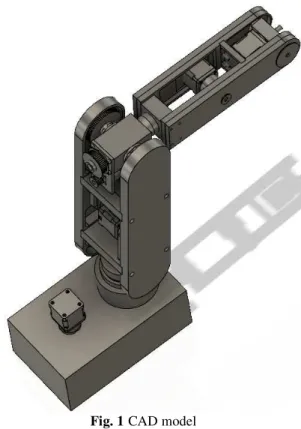
Abstract: The paper presents the design and manufacturing process for a 6 degrees of freedom robotic arm. The robotic arm was designed using the Fusion 360 program, after which the components of the robotic arm were manufactured using two CNC machines, namely: a Beaver VC5 milling machine and the Okuma Lb1 lathe. After assembling the robotic arm, tests for functionality were performed by actuating the stepper motors that are attached to the robot arm. The tests performed validated the performances of the robotic system.
Key words: robotic arm, CAD model, design, manufacturing, degree of freedom, G-Code
1. INTRODUCTION
The history of robotics dates back in the ancient world. The modern concept began to be developed with the onset of the Industrial Revolution, which allowed the use of complex mechanics, and the subsequent introduction of electricity. At present, robots are being extensively employed in industries like mechanism design, medical, modeling, control, defense, mechanics, automotive and Artificial Intelligence (AI).
Robots have many different functions such as machine tool load and unload functions, material handling, arc welding, assembly, resistance welding, spraying, painting etc. and they are generally used to perform highly repetitive task, unsafe and unpleasant task. The International Federation of Robotics reports that 72.7% of all industrial robots are used for pick-and-place, welding and assembly [1].
Robotics is a field of modern technology that crosses traditional engineering boundaries. Understanding the complexity of robots and their applications requires knowledge of mechanical engineering, electrical engineering, systems and industrial engineering, computer science and mathematics [2]. Nowadays, the
design of robotic arms is an attractive area of research. A serial manipulator is an open chain configuration in which rigid links are joined by either revolute of prismatic joints. The number of joints in an open chain manipulator is equal to the degree of freedom of the manipulator [3]. The robotic arm design is influenced by a number of variables such as geometry of the manipulator, dynamics involved, the structural characteristics of the linkage system and the actuator characteristics [4].
The kinematics control is an important task for be able to control a serial robot. There are multiple methods to establish the expressions that modeling the kinematic behavior for any mechanical structure, according to dedicated literature [5].
The paper is organized as follow: Section 2 presents designing of the components of the robotic arm. Section 3 presents manufacturing of the parts of the robotic arm, followed by conclusions and references.
2. DESIGNING OF THE COMPONENTS OF THE ROBOTIC ARM
complete parametric CAD tool developed by Autodesk (the AutoCAD editors).
It is considered by many as a uniting the best tools of cutting-edge programs like Rhino, Inventor, SolidWorks, Vault, and AutoCAD. This tool is complete integration into the cloud, allowing ease of access and collaboration from almost any device connected to the world wide web. It is used across a wide range of industries such as design, and automotive. Autodesk offers a full version of Fusion 360 for free to students, teachers, hobbyists and start-ups who make less than $ 100k a year [6].
Fig. 1CAD model
The main components of the robotic arm are:
• The base for the first joint and bearing
a) a)
Fig. 2 The base for the first joint and bearing
This base is attached to the base of the whole robot with 6 screws, the middle hole having the role of being a bearing for the shaft of the first joint. We used more types of bearings, depending of the needs that I had every certain part. The biggest one which is represented in figure 2, b is a 6306 deep groove ball bearing. It is used in the center hole of the base of the first joint presented earlier.
• Shaft for the first joint
Fig. 3Shaft for the first joint
The shaft used to rotate the first joint (figure 3). The working principle is simple as follows: on the tip of the shaft a pulley is placed that is connected with a belt to the small pulley on the first joint stepper shaft that will rotate, thus rotating the first joint and the whole robot.
• Shaft for the second joint
Fig. 4 Shaft for the second joint
cubical form because it must be fixated with the help of 3 screws on the first joint base, so it doesn’t move when the second joint rotates.
• Distance piece for the second joint
Fig. 5 Distance piece for the second joint
This part is used in two sections of the robot with the role of connecting the two arms that are used to move the first three joints. It has four holes in it for the four screws needed to fix the part on the arm.
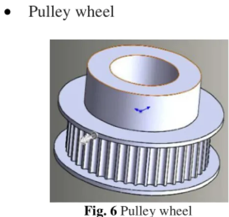
• Pulley wheel
Fig. 6 Pulley wheel
Via pulley wheel can achieve motion transmission by means of a drive belt from a motor to the robot shaft. Drive belts are usually made of leather, cotton, hemp, camel hair, rubber with canvas inserts.
We have used a variety of pulleys, varying in size and number of teeth. The biggest one that I have presented in figure 6 is the pulley used to transmit motion at the second joint. The rest of
the pulleys that I have used are presented in figure 16, after manufacturing them.
• Bolt for the fourth joint
Fig. 7 Bolt for the fourth joint
This is one of the two bolts used for the fourth joint bracket. They are both mounted on the bracket, with one of its tips having a pulley on it while the other one has a bearing. It has eight holes that are used to fix it on the bracket.
• Spindle for the fourth joint
Fig. 8 Spindle for the fourth joint
Shaft for the fourth joint (figure 8). It has the role of rotating the fourth, fifth and sixth joints.
• Arm for the second joint
It is one of the two arms that is used for the last three joints. It has a hole at the end of it where the bracket for the sixth couple is mounted. The three holes that are designed in a vertical line are for a distance piece and the hole in the middle is an opening used for the fifth joint stepper motor.
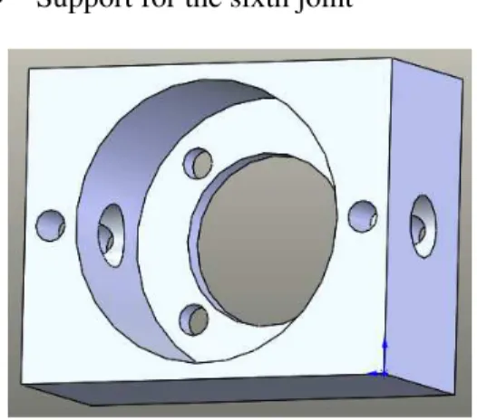
• Support for the sixth joint
Fig. 10 Support for the sixth joint
Support for the sixth joint, here the last stepper motor that is used to rotate the end effector is mounted, the holes on the sides having the role for fixating the shafts that come in the lateral holes.
• Base for the robot
Fig. 11 Base for the robot
The base of the whole robot, the hole on the right is used for the shaft and pulley of the first joint while the whole on the left is used for the first motor. The other holes are used to fix the parts mentioned on the base. The manufactured part will look different. The main reason for this is to
reduce the weight of the whole robot for ease of transportation.
3. MANUFACTURING OF THE PARTS
The machines that were used for the manufacturing of the parts were a lathe Okuma Lb15 (figure 12) and a milling machine Beaver VC5 (figure 13).
Fig. 12 Okuma Lb15
the sensor's output signal as input to the control logic). Collision avoidance is designing the machine to predict and prevent interference, for example, having the machine "know" the form and location of all fixturing so that it can foresee a crash and stop its own movement before crashing. Recent innovation includes technology to avoid chatter, both by predicting and preventing it and by early automatic detection and correction (via dynamic changes of speeds and feeds) when it does occur [7].
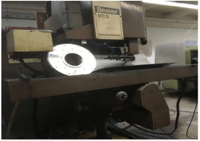
Fig. 13 Beaver VC5
Most CNC milling machines (also called machining centers) are computer controlled vertical mills with the ability to move the spindle vertically along the Z-axis. This extra degree of freedom permits their use in die sinking, engraving applications, and 2.5D surfaces such as relief sculptures. When combined with the use of conical tools or a ball nose cutter, it also significantly improves milling precision without impacting speed, providing a cost-efficient alternative to most flat-surface hand-engraving work. CNC machines can exist in virtually any of the forms of manual machinery, like horizontal mills. The most advanced CNC milling-machines, the multi axis machine, add two more axes in addition to the three normal axes (XYZ). Horizontal milling machines also have a C or Q axis, allowing the horizontally mounted work piece to be rotated, essentially allowing asymmetric and eccentric turning. The fifth axis (B axis) controls the tilt of the tool itself. When all of these axes are used in conjunction with each other, extremely complicated geometries, even organic geometries such as a human head can be made
with relative ease with these machines. But the skill to program such geometries is beyond that of most operators. Therefore, 5-axis milling machines are practically always programmed with CAM [8]. To achieve high productivity in the cutting processes is very important usage modern methods of simulation to avoid loss of used material [9].
The manufactured parts are the following:
• Belt extender
Fig. 14 Belt extender
This is one of the belt extenders that we have used. The principal behind it is that it has four groove holes so that when we use screws to mount it with the motor on the arm, it will move until the belt is extended at a desired length, after which the screws are fully screwed, and the belt is fully extended.
• Belt extender and motor bracket for the fourth joint
Fig. 15 Belt extender and motor bracket for the fourth joint
generating the required G-Code program for the milling machine Beaver VC5.
• Pulleys
Fig. 16 Pulleys
In figure 16 we present all the manufactured pulleys that we have used. We have bought them from a shop and the only manufacturing process we had to do was to broaden the holes in them, so they can fit on the shafts.
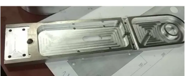
• Arm for the first two joints
Fig. 17 Arm for the first two joints
In figure 17 we present one of the arms for the first two joints. For the manufacturing part, the arms were pretty hard to do. Two additional parts had to be put on the Beaver milling table because the part was too long and couldn’t be fixed on the table for the manufacturing. After putting the additional parts, the SheetCam software was generated a G-Code program or the manufacturing process. This software is a low cost but feature packed CAM package, is suitable for milling, routing, plasma, waterjet, laser and oxy-fuel cutting. Computerized numerical control (CNC) machine tools are commonly used in modern manufacturing practice, to produce a variety of pieces. CAD/CAM software tools are essential for generating creative shapes and toolpaths for the
desired applications e.g. milling, engraving [10]. After the piece was created on the CNC machine, additional changes had to be made to it manually, making this the hardest part to manufacture overall.
• Base for the first joint
Fig. 18 Base for the first joint
The manufacturing of the base for the first joint was a straightforward process. Here is the mechanical transmission of the base. Besides the increased final product quality, the purpose is to improve robustness and functionality of these accurate displacements systems with respect to the regular current transmission systems [11]. At first the Okuma LB15 was used for the turning parts and then a drill was used for the holes.
• Support plate for motor
Fig. 19 Support plate for motor
Assembling the robot
Fig. 20 Assembling the robot
In figure 20 we have presented one of the steps of the assembling process. At this part of the assembling process, the last four stepper motors were mounted on the arms of the robot, with the last arm remaining to be mounted on the assembly. After this part, the assembled structure was mounted on the base of the robot.
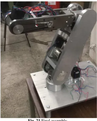
Final assembly
Fig. 21 Final assembly
In figure 21 we can see the final assembly of the robotic arm with 6 degree of freedom. For better reliability we can make a numeric analysis to
determine the displacements and stresses for the strength structure using Ansys software [12].
4. CONCLUSIONS
The paper presents design and manufacturing of a 6 degree of freedom robotic arm. The components of this robotic arm were first designed in Fusion 360 program, after which they were manufactured using a milling CNC machine and a lathe. After manufacturing the components, the robotic arm has been assembled and tests have been made for its functionality by actuating the stepper motors. Performed tests have validated the robotic system performances.
ACKNOWLEDGEMENT
This paper was supported by the project „Inter-University Partnership for Excellence in Engineering - PARTING - project coordinated by the Technical University of Cluj-Napoca” contract no. POSDRU/159/1.5/S/137516, project cofounded by the European Social Fund through the Sectorial Operational Program Human Resources 2007-2013, financed by UEFISCDI.
6. REFERRING
[1]World Robotics. Int. Fed. Robot., Frankfurt, Germany, 2013.
[2] Pandilov, Z., Dukovski, V., Comparison of the characteristics between serial and parallel robots, Acta Technica Corvininesis - Bulletin of Engineering, Jan-Mar2014, Vol. 7 Issue 1, p143-160. 18p.
[3] Murray, R., Li, Z., Sastry, S., Mathematical Introduction to Robotic Manipulation, vol. 29. 1994, ISBN-13: 978-0849379819. [4] Vertutt, J., Liegeois, A., General design
criteria for manipulators, Mechanism and Machine Theory, Volume 16, Issue 1, 1981, Pages 65-70, doi.org/10.1016/0094-114X(81)90052-5.
1221-5872, pag. 253-660, 2018, Cluj-Napoca, România
[6] ***,all3dp.com/1/autodesk-fusion-360-free- download-full-version/
[7]***,en.wikipedia.org/wiki/ OkumaCorporation
[8] ***, en.wikipedia.org/wiki/Milling _(machining)
[9] Koukach, D., Pop. G.,, Preja, D., Machining process modeling, Acta Tehnica Napocensis, Series: Applied Mathematics and Mechanics, vol. 54, Issue IV, ISSN 1221-5872, pag. 659-668, 2011, Cluj-Napoca, România
[10] Matei, C., Steopan, A., Blebea, I., Cam in the cnc machining process, Acta Tehnica Napocensis, Series: Applied Mathematics and Mechanics, vol. 55, Issue IV, ISSN 1221-5872, pag. 203-206, 2012, Cluj-Napoca, România,
[11] Sucală, M., Veja, A., Mechanical transmissions for accurate displacements,
Acta Tehnica Napocensis, Series: Applied Mathematics and Mechanics, vol. 54, Issue I, ISSN 1221-5872, pag. 43-48, 2011, Cluj-Napoca, România,
[12] SIMION M., BOTEAN, A., BEJAN M., Numerical analysis of state of stresses and deformations of an industrial serial robot 5r, Acta Tehnica Napocensis, Series: Applied Mathematics and Mechanics, vol. 54, Issue IV, ISSN 1221-5872, pag. 675-680, 2011, Cluj-Napoca, România
[13] Raghaven, M,, Roth, B., Kinematic analysis of the 6R manipulator of general geometry. In: Proc fifth int symp on robotics research; 1990. pages: 263–9. ISBN:0-262-13253-2.
[14] Chen, Y., Leitmann, G., Robust control for rigid serial manipulators: A general setting. In American Control Conference (Vol. 2, pp. 912–916). IEEE. ISBN: 0-7803-4530-4.
PROIECTAREA ŞI FABRICAREA UNUI BRAŢ ROBOTIC CU 6 GRADE DE
LIBERTATE
Rezumat: Lucrarea prezintă proiectarea şi procesul de fabricaţie pentru un braţ robotic cu 6 grade de libertate. Bratul robotic a fost proiectat cu ajutorul programului Fusion 360, după care componentele braţului robotic au fost fabricate cu ajutorul a două masini unelte cu comandă numerică şi anume, o maşină de frezat model Beaver VC5 şi un strung model Okuma Lb1. După asamblarea braţului robotic s-au făcut teste pentru funcţionalitate prin acţionarea motoarelor pas cu pas care sunt ataşate braţului robotului. Prin testele efectuate s-au validat performanţele sistemului robotic.
Florin COVACIU,Dr. Ing., Lecturer, Technical University of Cluj-Napoca, Department of Design Engineering and Robotics, [email protected], Phone: 0755566491, B-dul Muncii 103-105, Cluj-Napoca, ROMANIA