Closed Loop Fuzzy Logic Control of 3-
∅
BLDC Motor Driven by
High Voltage Gain Interleaved Boost Converter
Leela Krishna.K1, Viswanath.N2& Bhargav.A3
1, 2&3B.Tech Final Year, Dept of EEE, Regency Institute of Technology, Pondicherry University.
Abstract: — This paper deals the Brush Less DC Motor (BLCDM) driven by an efficient closed loop fuzzy logic based high voltage gain interleaved boost converter. The proposed high voltage gain interleaved boost converter in this paper is to boosts an input DC voltage to required DC output voltage. The proposed converter performs the inverter operation to drive the BLCDM. For fine tuning and dynamic responses of BLDCM, such as speed, torque, stator current and stator voltage an improved closed loop fuzzy logic control method is adapted in this paper. The control technique is modeled and simulated in MATLAB 2009a GUI environment using Simulink and Sim Power System set tool boxes. Finally the resultant simulation waveforms shows some more accuracy with the proposed closed loop fuzzy logic control technique as compared with conventional control techniques. The control techniques to drive the BLDCM are modeled and simulated in MATLAB 2009a GUI environment using Simulink and Sim Power System set tool boxes.
Keywords: Brush Less DC Motor (BLCDM), closed loop fuzzy logic control, Interleaved Boost Converter, PI Controller
I. I
NTRODUCTIONThe brushless motor, unlike the DC brushed motor, has the permanent magnets glued on the rotor. It has usually 4 magnets around the perimeter. The stator of the motor is composed by the electromagnets, usually 4 of them, placed in a cross pattern with 90o angle between them. The major advantage of the brushless motors is that, due to the fact that the rotor carries only the permanent magnets, it needs of NO power at all. No connection needs to be done with the rotor, thus, no brush-commutator pair needs to be made! This is how the brushless motors took their name from. This feature gives the brushless motor great increament in reliability, as the brushes wear off very fast. Moreover, brushless motors are more silent and more efficient in terms of power consumption.
Brush Less DC Motor (BLCDM) has significant importance because of inherent properties like high efficiency, low noise operation,
maintenance free, etc. .. BLDC motors are widely used for many applications in areas like automation, military, medical and for other appliances etc. Hence, it is important to design low cost and efficient speed controller for BLDCM.
The trick of operation in BLDC motors is the Hall sensor that is attached to the stator. It faces the magnets perpendicularly and can distinguish if the North or South pole is in front of it. Using a Hall sensor will result in an increase of the overall price of the motor. Moreover, there are situations that a sensor cannot be used, as for example in submersible pumps, or in applications where the wiring must be kept to minimum. In such applications, the sensorless BLDC can be used instead. The operation of such motor is based on the BEMF effect. The BEMF (Back Electro-Magnetic Force) is inducted by the movement of a permanent magnet in front of a stator coil.
Many techniques for BLDCM control have been developed such as PI, PID, fuzzy logic controller, adaptive fuzzy logic controller. Fuzzy logic is based on fuzzy set theory, which is used for many control applications. All controlling designs of BLDCM also be used for sensor less BLDCM control. In which back EMF waveform is observed and using different algorithms, speed of BLDC motor can be estimated, which is compared with reference speed[1].
In this paper the required input supply for the BLCDM is provided by the high voltage gain interleaved boost converter, which performs the inverter operation and also boosts the input DC level to a maximum output D.C level. High voltage gain DC boost converter that proposed in this paper is a combination of two 2 phase interleaved boost converter, which is a non-isolated boost converter.[2]
appraisal of the proposed hybrid system is presented in the Section V.
II. D
ESIGNINGP
ROCESSA. Design of High Voltage Gain Interleaved DC Boost Converter :
High voltage gain DC boost converter that proposed in this paper is a combination of two 2 phase interleaved boost converters and is shown by Fig.1 [2]. The four power electronic based switching devices used in the Fig.1 are controlled in 90 phase delay to each other’s simultaneously (interleave technique method), in order to smooth output ripple current, raising power rating and efficiency[4].
For the Fig.1 , from KVL , voltage equation is given by equation(1)
= + − (1)
Where, = Supply voltage
= Output voltage
= Voltage across Capacitor “Ca”
= Voltage across Capacitor “Cb”
Voltage gain (G) for the Fig.1 is given by equation (2)
= =(1 + )(1 − ) (2)
Where, D = Duty cycle.
Fig.1. Proposed High voltage gain Interleaved DC boost converter
In the proposed high voltage gain interleaved DC boost converter, there is a considerable reduction in input current ripple and inductor size. The output voltage ripple of the circuit depends on the size of capacitor. The proposed converter should be operated in Continuous Conduction Mode (CCM). Based on the equations (3) & (4), the inductance & capacitance values respectively can be decided for the proposed converter.
=4. ∆ .. (3)
=2. ∆. . (4)
Where,∆ = Maximum current ripple
∆ = Output voltage ripple
= Output current
= Switching frequency
For the proposed converter, all the designed parameters are given by the Table.1. MATLAB based simulation diagram of proposed High voltage gain Interleaved DC boost converter is shown by Fig.2
Fig.2. MATLAB based simulation diagram of proposed High voltage gain Interleaved DC boost converter
B. Design of Brush Less DC Motor (BLDCM) :
Fig.3. Equivalent circuit of a BLDC Motor
The windings of a BLDC Motor modelled as a series combination of RL and speed depends on the voltage source, which is known as the back EMF (E)[4]. The BLDCM has three phases and those phase voltages are given by the equations (5), (6) & (7).
= . + + (5)
= . + + (6)
= . + + (7)
Where, = Phase “A” voltage
= Phase “B” voltage
= Phase “C” voltage
= Phase “A” current
= Phase “B” current
= Phase “C” current
= Stator resistance
=Phase “A” stator flux linkages
= Phase “B” stator flux linkages
= Phase “C”stator flux linkages
=Phase “A” back EMF
=Phase “B” back EMF
=Phase “C” back EMF
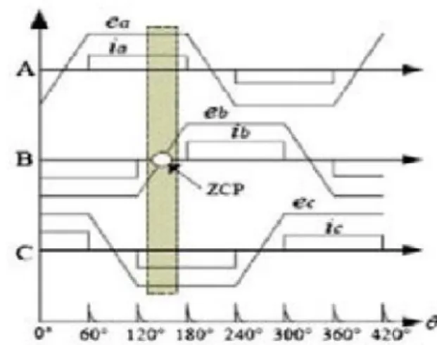
Fig. 4. Shows the relationship between the back EMF waveform of an ideal BLDC motor and the armature current (I) . The shape of the currents should in rectangular waveform and must be inphase with the corresponding phase back EMF [4].
Fig.4. BLDCM Waveforms of ideal back EMF and phase current
If the self and mutual inductance around the air gap are consider to be constant, then there will be a direct relation between the applied source voltage to the phase terminals (V) and the induced back EMF (E) is given by equation(8) and the electromagnetic torque (Te ) in N.M is given by equation (9)
∝ (8)
=( . + . + . ) (9)
Where, = Rotor mechanical speed
III. C
ONTROLT
ECHNIQUESAt present, the PI controller is most widely adopted in industrial application due to its simple structure, easy to design and low cost. Despite these advantages, the PI controller fails when the controlled object is highly nonlinear and uncertain. PI controller will eliminate forced oscillations and steady state error resulting in operation of on-off controller and P controller respectively. However, introducing integral mode has a negative effect on speed of the response and overall stability of the system. Thus, PI controller will not increase the speed of response. It can be expected since PI controller does not have means to predict what will happen with the error in near future. This problem can be solved by introducing derivative mode which has ability to predict what will happen with the error in near future and thus to decrease a reaction time of the controller. PI controllers are very often used in industry, especially when speed of the response is not an issue. A control without D mode is used when
ii. Large disturbances and noise are present during operation of the process
iii. There is only one energy storage in process (capacitive or inductive) iv. There are large transport delays in the
system.
Closed loop fuzzy logic control technique gives the better performance as compared with the conventional PID controller, hence, in this section mainly focused on the speed control technique for the BLDCM.. The block diagram of the proposed control technique is shown in Fig.5
Fig.5. Proposed block diagram of closed loop fuzzy logic control technique fed to BLDCM
Fuzzy logic consist of three basic steps as fuzzification, decision making using knowledge base and defuzzification which is shown in Fig.6.
Fig.6.Basic idea block diagram of fuzzy logic control technique
Inputs error and change in error are fuzzified using fuzzy set theory and fuzzification process. Fuzzy set is represented by a membership function defined on universe of discourse. Universe of discourse is space where fuzzy variables are defined. In the proposed system, error and change in error are the two inputs to the fuzzy logic controller (FLC) and a single output exists. 9 membership functions are defined for inputs and outputs. Using rule editor window as shown in Fig. 7, if-then rules are defined for relation of inputs and output. By using two inputs to obtain the single out 81 rules are used in the proposed controller. Fuzzy
rules are given by the Fig.9 and its surface viewer is given by Fig.8. For this system, 9-different variables will be defined are NB- Negative Big, NM- Negative Medium, NS- Negative Small, Z-Zero, PS- Positive Small, PM-Positive Medium and PB- Positive Big. Defuzzzification is process in which fuzzy variables are again translated into regular format. The MATLAB based simulation diagram of proposed closed loop fuzzy logic controller is given by Fig.10.
Fig.7. Window diagram of FIS Editor
Fig.8. Window diagram of Surface Viewer of proposed Fuzzy Logic Controller
Fig.10. MATLAB based simulation diagram of proposed closed loop fuzzy logic controller
Fig.11. shows the input voltage to the proposed high voltage gain interleaved boost converter , its value is nearly 17.4 V and theo utput from the converter is nearly 248 V . Hence the proposed high voltage gain interleaved boost converter boosts the low level input DC value to a maximum output DC value.
Fig.11. MATLAB based simulation input & output wave forms of proposed high voltage gain interleaved
boost converter
Fig.12 shows the phase A stator current ( ) and Phase “A” back EMF ( ) of the BLDC Motor.
Fig.13. Stands for MATLAB based simulation waveforms of Electromagnetic torque (Te) in N.M and Rotor speed (N) in rpm of the BLDC Motor with Conventional PID controller. Here, Settling time ( ) is 0.1 Seconds for both the“Te”and“N”.
Fig.14. Stands for MATLAB based simulation waveforms of Electromagnetic torque, “Te” in N.M of the BLDC Motor with proposed closed loop
fuzzy logic controller. Here, is 0.05 Seconds for the “Te”.
Fig.14. Stands for MATLAB based simulation waveforms of Rotor speed, “N” in rpm of the BLDC Motor with proposed closed loop fuzzy logic controller. Here, is 0.05 Seconds for the “N”
Fig.12. MATLAB based simulation and wave
forms of the BLDC Motor
Fig.13. MATLAB based simulation waveforms of BLDC
Fig.14. MATLAB based simulation waveforms of BLDC Motor “Te”with proposed closed loop fuzzy logic
Controller
Fig.15. MATLAB based simulation waveforms of BLDC Motor “N”with proposed closed loop fuzzy logic
Controller
TABLE.I.SPECIFICATION OF PROPOSED SYSTEM
PARAMETER RATING
BLDC Motor stator resistance 2.8750Ω
BLDC Motor stator inductance 8.5mH
PID controller , Kp 0.004
PID controller , Ki 0.7
PID controller , Kd 0.001
Boost converter capacitance C 470µF
Boost converter inductance L 840 µH
BLDCM rated speed N 1500 rpm
IV
.C
ONCLUSIONThe proposed closed loop fuzzy logic controller gives the better response as compared with the conventional PID controller. Settling time with PID Controller is about 0.1 Secs and it is with proposed closed loop fuzzy logic controller is 0.05 Secs . Hence dynamic response of the overall system improved with the proposed closed loop fuzzy logic controller.
R
EFERENCES[1] Debjyoti Chowdhury, Madhurima Chattopadhyay and Priyanka Roy, “Modelling and Simulation of Cost Effective Sensorless Drive for Brushless DC Motor”, pp.no 279-286, Elsevier CIMTA- 2013.
[2] M.V. Ramesh, J. Amarnath, S. Kamakshaiah, G. S. Rao, “Speed Control of Brushless DC Motor by Using Fuzzy Logic PI Controller”, ARPN journal of engineering and applied science, vol. 6, No. 09, pp. 55-62, Sept. 2011.
[3] Weerachat Khadmuna and Wanchai Subsingha, “High Voltage Gain Interleaved DC Boost Converter Application for Photovoltaic Generation System”,pp no.390-398, Elsevier 2012.
[4] W. Yuanxi, Yu Yali, Z. Guosheng, S. Xiaoliang, “Fuzzy Auto- adjust PID Controller Design of Brushless DC Motor”, Elsevier International conference on medical physics and biomedical engineering, pp. 1553-1559, 2012.
[5] Bhim A. Rajan, R. Raj, S. Vasantharathna, “Fuzzy Based Reconfigurable Controller for BLDC Motor”, IEEE, International conference on computing, communication and networking technologies, 2010.
[6] R. Arulmozhiyal, “Design and Implementation of Fuzzy PID Controller for BLDC Motor using FPGA”, IEEE, International conference on power electronics, drives and systems, Dec, 2012.
Fig.14. MATLAB based simulation waveforms of BLDC Motor “Te”with proposed closed loop fuzzy logic
Controller
Fig.15. MATLAB based simulation waveforms of BLDC Motor “N”with proposed closed loop fuzzy logic
Controller
TABLE.I.SPECIFICATION OF PROPOSED SYSTEM
PARAMETER RATING
BLDC Motor stator resistance 2.8750Ω
BLDC Motor stator inductance 8.5mH
PID controller , Kp 0.004
PID controller , Ki 0.7
PID controller , Kd 0.001
Boost converter capacitance C 470µF
Boost converter inductance L 840 µH
BLDCM rated speed N 1500 rpm
IV
.C
ONCLUSIONThe proposed closed loop fuzzy logic controller gives the better response as compared with the conventional PID controller. Settling time with PID Controller is about 0.1 Secs and it is with proposed closed loop fuzzy logic controller is 0.05 Secs . Hence dynamic response of the overall system improved with the proposed closed loop fuzzy logic controller.
R
EFERENCES[1] Debjyoti Chowdhury, Madhurima Chattopadhyay and Priyanka Roy, “Modelling and Simulation of Cost Effective Sensorless Drive for Brushless DC Motor”, pp.no 279-286, Elsevier CIMTA- 2013.
[2] M.V. Ramesh, J. Amarnath, S. Kamakshaiah, G. S. Rao, “Speed Control of Brushless DC Motor by Using Fuzzy Logic PI Controller”, ARPN journal of engineering and applied science, vol. 6, No. 09, pp. 55-62, Sept. 2011.
[3] Weerachat Khadmuna and Wanchai Subsingha, “High Voltage Gain Interleaved DC Boost Converter Application for Photovoltaic Generation System”,pp no.390-398, Elsevier 2012.
[4] W. Yuanxi, Yu Yali, Z. Guosheng, S. Xiaoliang, “Fuzzy Auto- adjust PID Controller Design of Brushless DC Motor”, Elsevier International conference on medical physics and biomedical engineering, pp. 1553-1559, 2012.
[5] Bhim A. Rajan, R. Raj, S. Vasantharathna, “Fuzzy Based Reconfigurable Controller for BLDC Motor”, IEEE, International conference on computing, communication and networking technologies, 2010.