Keynote Lecture
Tuesday 16 October 2001, 09.00–09.40
Multislice CT in tumor detection
Paul M Silverman
Professor of Radiology, Department of Radiology, Division of Diagnostic Imaging, MD Anderson Cancer Center, Houston, TX, USA
This seminar will address the dramatic impact of multislice (multidetector) CT upon imaging the oncologic patient. This technology is responsible for a dramatic change in the speed and ability for diagnostic radiologists to detect dis-ease. Technology has advanced rapidly in the last 20 years from single-slice CT scanners to helical (spiral) technology. Continuous acquisitions of multiple images represent the newest generation of scanners, referred to as multislice CT. Presently allowing four slices to be acquired simultaneously with newer scanners allowing eight-slice acquisitions. In this context I will address the fundamental technical principles behind these scanners and their impact on clinical protocols for the oncologic patient.
Introduction
The development of multislice technology represents a substantial technological advance in CT. The dramatic 4- to 8-fold increase in imaging speed not only makes the examination more comfortable but also provides a higher quality of examination, more flexibility for ning with thinner sections, increased flexibility in scan-ning during multiple phases of hepatic enhancement, including the early and late hepatic arterial phase (HAP) and the portal venous phase (PVP) phase, and the ability to perform exquisite vascular, 3-dimensional (3-D) imaging,
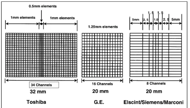
When conventional helical CT is utilized, there is a continuous acquisition limited to a single slice. This is related to the intrinsic technology of the scanner, which consists of a detector made up of an array of rectangular channels and usually measuring approximately 1 mm transversely and 20 mm in the z-axis (Fig. 1). The collimation determines the slice thickness. These scan-ners generally produce slice thicknesses of 1, 3, 5, 7 or 10 mm. With the transformation to multislice scanners, various manufacturers have developed different arrays (Fig. 1). Instead of being long and rectangular the arrays are divided into cross-sectional, rectangular matrices that generally fall into two different categories. One group has detector elements of equal width along the
z-axis (matrix detectors) and the second has detector elements of unequal width (adaptive or hybrid array detectors). An example of the equal-width detector array would be the General Electric Medical Systems, whereas the unequal-width detector arrays are represented by Marconi, Siemens and Toshiba Systems. The latter systems tend to have thinner sections in the middle of the detector array and are, in general, sub-second scan-ners with scans times ranging from 0.8 to 0.5 s. Because of the new type of detector array, one must appreciate that there is reduction in efficiency based on the fact that there are thin septae between detectors in thez-axis that absorb radiation but produce no data, and that the systems generally produce four slices per rotation rather than one and thus the amount of unusable radiation (penumbra) is increased, thus an obligatory increase in the radiation dose (Table 1).
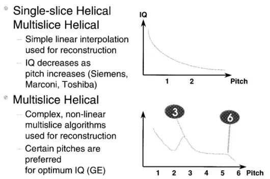
Recent technological advances in hardware and tracking software for conventional helical CT have made us familiar with the use of the term pitch, defined below.
As pitch increases, the table speed increases. The patient’s dose decreases, image noise increases, but there is improved coverage in the z (longitudinal) axis. In view of different vendors’ proprietary technological development, there are now two definitions of pitch for multislice. With the introduction of multislice CT, the definition of pitch depends upon the vendor. The first is the conventional definition as described above which applies to equipment marketed by Siemens, Marconi and Toshiba and a second definition applies to General Electric.
The first definition, based on ‘beam pitch’, is defined below.
In contrast the other manufacturer, General Electric, uses pitch as ‘slice pitch’ thus:
These definitions are synonymous, just different terminology! It is thus important to understand the differences when using or comparing equipment. A pitch of 0.75 (Siemens, Marconi, Toshiba) is equivalent to Pitch=3:1 (HQ), General Electric. Additionally, the three vendors described have pitches, which are variable and range between one and two, whereas General Electric allows only a ‘binary decision’ using the high quality HQ (3:1) or High Speed HS (6:1) mode (Fig. 2). Using the technology available on this machine, it has
been found that image quality related to increasing pitch has certain ‘sweet spots’ at 3:1 and 6:1 where there is better operational performance. Other vendors have found a rather smooth and decreasing curve with increasing pitch, explaining the different approaches in terminology. Understanding this is important in establishing patient protocols.
Using the detector technology available on the GE system, the smallest slice thickness is 1.25 mm and, with the collimator open to expose only these four central detectors, the total coverage is 5 mm. The second detec-tor configuration is 42.5-mm slices exposing the central eight detectors, 10 mm. A third detector configu-ration is for 3.75 mm thick slices with the collimator open to the central 12 detectors (minimum slice thick-ness 3.75 mm). The fourth detector configuration is 5-mm thick slices with the collimator open to all 16 detectors and the minimum achievable slice thickness being 5 mm. While one cannot reconstruct thinner sec-tions than the thinnest detector configuration, thicker slices can be reconstructed and can decrease any arti-facts, i.e. posterior fossa between petrous bones, how-ever, thinner slices can be reconstructed. Additionally, thinner sections can be reconstructed using specific choices as long as one realizes that scans cannot be reconstructed thinner than the individual slice thickness. For example, if the abdomen is scanned by the 45 mm detector configuration, P=0.75 table speed=15 mm/ rotation, the minimum slice thickness is 5 mm. However, if it is scanned 42.5 mm, P=1.5, identical table speed=15 mm/rotation, the slices can be reconstructed at 5 mm thickness or the raw data used for thinner sections of 2.5 and 3.75 mm.
Figure 1 Detector comparison: vendors.
Table 1 Multi-slice CT: slice profile aspects
Slice profile broadening (FWHM): Collimation Pitch Standard
helical Multi-slicehelical
5 mm 1.0 N.S. N/A
5 mm 1.5 15% 5.8 mm N/A
5 mm 2.0 30% 6.5 mm N/A
5 mm 3.0 4% 5.2 mm
5 mm 6.0 28% 6.4 mm
Head and neck
In general, there have been relatively limited applica-tions for multislice scanners in head and neck imaging. This is mainly related to the short period of scanning time required for the brain and the inability to angle the gantry in studying the neck. However, specific appli-cations are evident in the area of 3-D imaging where exquisite 3-D vascular detail can be demonstrated if one performs scans in the arterial phase and venous anatomy in the later phase. The rapid scan times of multislice have also added to the quality of images for staging laryngeal neoplasms.
Chest
One of the major impacts has been in the area of the detection of pulmonary emboli. Previously the pivotal
study was the ventilation profusion (V/Q) scan. With the introduction of multislice CT and the ability to detect segmental pulmonary emboli it has increased to approxi-mately 93% and the depiction of even subsegmental disease from 37% with conventional helical scanners to 61%. This is in terms of visualization of the vascular structures. The recommended scan technique is at a delay of 25 s, with an injection rate of 4 ml/s and scanning from above the aorta to the diaphragm in a single breath hold. Images can be obtained with collima-tion as thin as 1.25 mm, but 3 mm is used as a standard. Recent studies have demonstrated less than 1% inci-dences of fatal PE in patients with a negative CT arteriogram who are followed for period of 3 to 6 months. In addition, scans can be performed in a single setting of the lower extremities to evaluate for deep venous thrombosis (DVT), eliminating the need for sonography.
Figure 2 Helical pitch and quality.
Liver
The two most important major phases in a liver study are the hepatic arterial phase (HAP) and the portal venous phase (PVP), although scans can also be per-formed precontrast and in the equilibrium phase. A single-slice helical CT scanner requires approximately 20–25 s to scan the entire liver, whereas with multislice CT, depending on the pitch and slice thickness, the entire liver can be scanned in 5–15 s. For most protocols a scan delay of 70 s is appropriate with conventional rates of contrast injection of 2–4 ml/s. At faster rates earlier scanning maybe desired. One option is to use computer-assisted scanning technology, i.e. cast (Smart-Prep, GE), to assure scanning at the optimal time because most pathology, especially metastatic disease, is hypovascular. When confronted with hypervascular lesions most commonly resulting from metastatic islet cell tumours, melanomas, choricarcinomas, renal cell carcinomas, thyroid carcinomas and in some cases breast carcinomas, a dual-phase study is recommended. The addition of this component to the study can increase lesion detection from 8 to 13% compared with PVP imaging alone. The arterial phase has a value additional to just detecting hypervascular lesions. This portion of this study can be utilized for the production of superb 3-D imaging of the vascular system depicting hepatic arterial anatomy pre-operatively, and in patients who are candidates for intra-arterial chemotherapy. Multislice flexibility may avoid more invasive techniques such as catheter CT arterial portography. In cases where a CT angiogram is specifically desired, a triple- rather than dual-phase study may be substituted with an early hepatic arterial phase (HAP) performed 10–15 s after contrast followed by the late HAP and PVP phases. (HAP=25 s, PVP=70 s time of initiation 5 or 7 mm collimation and injection rates of 4–6 ml/s).
In some cases adequate hepatic enhancement has been reported with iodine doses that are 25% lower than conventional CT. If a patient’s weight is taken into account, an even more pronounced reduction in contrast can be appreciated, resulting in significant cost-savings. In developing scanning protocols the radiologist must first appreciate the collimation that is required for detection of the lesion size. Other major considerations include the extent of coverage and the requirement for scanning during certain phases such as for hypervascu-lar tumors (Figs 3 and 4). Thus the selection of pitch comes into play. Finally, these scanning parameters must be reviewed in the context of the overall radiation dose to the patients.
Spleen
Evaluating the spleen can be difficult with multislice CT because scans of the spleen often demonstrate a very inhomogeneous appearance referred to as serpiginous. Occasionally, confluent serpiginous areas can mimic real low attenuation defects, but are not seen with repeat scans at a later time.
Kidneys
Scans performed during the optimal PVP phase for imaging the liver result in the kidneys being imaged in the corticomedullary (CM) phase. In this phase the medullary portion is low attenuation and therefore lesions within the medullary portion can easily be missed. In patients with suspected renal pathology, it is recommended that scans be performed after completion of the initial pass when the kidneys are homogeneous in the nephrogram (NP) phase, where there is excellent conspicuity of lesions. Even though most results show benign cysts, occasionally small renal cell carcinomas, lymphomas, or metastatic disease can be missed. An important and new application for multislice CT is in the area of the clinical symptoms of flank pain. Noncontrast CT scans using 5-mm sections through the kidneys to the bladder have changed emergency evalu-ation of right flank pain and is now the pivotal technique for finding renal and ureteral calculi. It is also helpful in discovering other etiologies such as diverticulitis, appendicitis or mass lesions. Most recently adopted techniques have been used to visualize the kidneys in the expiratory phase to identify the ureters in an attempt to replace or supplement the IVU and demonstrate lesions in the urethra such as transitional cell carcinoma or metastases.
Pelvis
Staging of pelvic malignancies is primarily performed with MRI. However, the identification of nodal disease from vascular structures has been improved with multislice CT, as vascular structures are now greatly enhanced and easily distinguished from lymph nodes, even when long examinations are presented with limited amounts of contrast.
Three-dimensional
The introduction of multislice scanners and the contin-ued improvement of 8-slice systems have now allowed ready depiction of vascular structures, allowing for improved staging of pancreatic neoplasms by identifying the encasement of the splenic vein. This may necessitate a splenic vein graft or identification of encasement of the superior mesenteric artery, indicative of nonresect-ability. Other 3-D imaging applications include the identification of accessory renal vessels, planning partial nephrectomy and nephron-sparing surgery, as well the identification of the vascular anatomy and vascular anomalies in the context of liver resections for primary or metastatic disease.
Conclusion
and establishing optimal protocols is critical to the radiologist.
Further reading
[1] Baron RL, Oliver JH, Dodd GD, Nalesnik M, Holbert BL, Carr BI. Hepatocellular Carcinoma: evaluation with bi-phasic, contrast-enhanced helical CT. Radiology 1996; 199: 505–11.
[2] McCullough CH, Zink FE. Performance evaluation of a Multislice CT system. Med Physics 1999; 26: 2223–7. [3] Berlin LL, Smith JK. Multidetector array CT: once again
technology creates new opportunities. Radiology 1998; 209: 327–9.
[4] Hui HD, Foley WD, Fox SH. Four Multidetector — row helical CT: image quality and volume coverage speed. Radiology 2000; 215: 55–62.
[5] Silverman PM, Roberts S, Teffet MC et al. Helical CT of the liver: clinical application of an Automated Computer
Technique, SmartPrep for obtaining images with optimal contrast enhancement. Am J Radiol 1995; 165: 73–8. [6] Ichikawa T, Ohtomo K, Takahashi S. Hepatocellular
carci-noma: detection with double-phase helical CT during arterial portography. Radiology 1996; 198: 284–7.
[7] Silverman PM. Multislice Computed Tomography Principles in Practice: A comprehensive guide to CT protocols. Philadelphia: Lippincott, Williams & Wilkins, 1998. [8] Rydberg J, Buckwalter KA, Caldemeyer KS et al.
Multi-section CT: scanning techniques and clinical applications. Radiographics 2000; 20: 1787–806.
[9] Husband JES, Reznek RH. Imaging in Oncology. Oxford: ICIS Medical Media Ltd, 1998.
[10] Silverman PM, Kalender WA, Hazle JD. Common terminology for single and multislice helical CT. Am J Radiol 2001; 176: 1135–6.